
AN AUGMENTED STATE VECTOR APPROACH TO GPS-BASED
LOCALIZATION
Francesco Capezio, Antonio Sgorbissa and Renato Zaccaria
Laboratorium D.I.S.T. – University of Genova
Keywords: Mobile Robotics; Localization; State Estimation.
Abstract: The ANSER project (Airport Night Surveillance Expert Robot) is described, exploiting a mobile robot for
autonomous surveillance in civilian airports and similar wide outdoor areas. The paper focuses on the
localization subsystem of the patrolling robot, composed of a non-differential GPS unit and a laser
rangefinder for map-based localization (inertial sensors are absent). Moreover, it shows that an augmented
state vector approach and an Extended Kalman filter can be successfully employed to estimate the colored
components in GPS noise, thus getting closer to the conditions for the EKF to be applicable.
1 INTRODUCTION
The work described in this paper is part of the
ANSER
1
project, an ongoing project for autonomous
surveillance in civilian airports and similar wide
outdoor areas
2
. Within this framework, a system
composed of two parts is foreseen: a mobile
autonomous robot (also referred to as UGV –
Unmanned Ground Vehicle), whose sensors and
actuators have been especially crafted to
successfully perform night patrols, and a fixed
supervision station, which is under direct control of
a human supervisor. The main surveillance task is to
detect differences between perceived and expected
environmental conditions; in particular to verify the
state of doors and barriers, to verify the presence of
allowed/non allowed persons in the current area, and
to identify unexpected objects. In ANSER, this is
done through the combination of a laser rangefinder
and an on-board panning video camera, and it
obviously requires a sufficient accuracy in self-
localization to be able to recognize “what is normal”
and “what is not” in a given area. A first system
prototype is currently being tested at the Villanova
d’Albenga Airport (Figure 6), where it is asked to
1
ANSER is an acronym for Airport Night Surveillance
Expert Robot, and the Latin name for “goose” (referring to
the Capitoline Geese which –according to tradition -
neutralized a nighttime attack by the Gauls during the
siege of Rome).
2
Funded by the Parco Scientifico Tecnologico della
Liguria (PSTL), www.pstliguria.it.
patrol a wide outdoor area and the indoor Airport
Terminal.
In the last years several autonomous surveillance
systems based on a mobile platform have been
presented.
A very interesting example in this sense is the
MDARS project, a joint USA Army-Navy
development effort (Heath-Pastore, et al., 1999).
The MDARS goal is to provide multiple mobile
platforms that perform random patrols within
assigned areas of warehouses and storage sites, both
indoor and in semi-structured outdoor environments,
such as storage yards, dock facilities, and airfields.
MDARS-E apparently meets the requirements of the
ANSER domain. However, it is immediate to notice
that high performance are obtained by over
equipping the system with a huge set of different
sensorial devices and – consequently – providing
adequate onboard computing power to process the
huge amount of available data. For example, the
localization and navigation subsystem of MDARS-E
requires the joint use of a differential GPS, a fiber-
optic gyro and the recognition of retroreflective
landmarks via a laser-based proximity sensor.
In (Saptharishi, et al., 2002) a network of mobile
all-terrain vehicles and stationary sentries are
exploited in an autonomous surveillance and
reconnaissance system. The vehicles are equipped
with video cameras, and are able to detect moving
objects, classify them using a differential learning
algorithm, and track their motion. Each robot relies
for localization on a Differential GPS and an IMU
(Inertial Measurement Unit); a PC/104 for the
252
Capezio F., Sgorbissa A. and Zaccaria R. (2007).
AN AUGMENTED STATE VECTOR APPROACH TO GPS-BASED LOCALIZATION.
In Proceedings of the Fourth International Conference on Informatics in Control, Automation and Robotics, pages 252-258
DOI: 10.5220/0001626302520258
Copyright
c
SciTePress
locomotion task, and three networked PCs for
planning, perception and communication are
required.
In (Vidal, et al., 2002) a team of UAVs
(Unmanned Arial Vehicle) and UGVs pursue a
second team of evaders adopting a probabilistic
game theory approach (pursuit-evasion is a classical
problem that had been deeply investigated (Volkan,
et al., 2005)). Also in this case, the robots need
enough computational power to manage a
Differential GPS receiver, an IMU, video cameras
and a color-tracking vision system.
In (Rybski,et al., 2002) a multirobot surveillance
system is presented. A group of miniature robots
(Scouts) accomplishes simple surveillance task using
an on-board video camera. Because of limitations on
the space and power supply available on-board,
Scouts rely on remote computers that manage all the
resources, compute the decision processes, and
finally provide them with action control commands.
As one could expect, autonomous navigation and
self-localization capabilities are a fundamental
prerequisites in all these systems. This is the reason
why, starting from a minimal configuration in which
self-localization relies on an Inertial Measurement
Unit (IMU) and a Carrier Phase, Differential GPS
receiver (CP-DGPS) – see for example (Panzieri, et
al., 2002; Schönberg, et al., 1995; Dissanayake, et
al. 2001; Farrell, et al., 2000) -, a very common
approach is to equip the mobile platform with a large
set of sensors (video cameras, PIR sensor, RFID
sensor, sonar, laser range finders etc.), thus
consequently requiring a high computational power
and complex data filtering techniques.
In partial contrast with this “over equipping”
philosophy, the ANSER self-localization sub-system
relies only on a standard (non-differential) GPS unit,
and on a laser rangefinder. Unfortunately, GPS data
are known to be affected by low-frequency errors
that cannot be modeled as zero mean, Additive
White Gaussian Noise (AWGN), thus making
simple state estimation approaches (e.g., Kalman
Filter) unfeasible (Sasiadek, and Wang, 2003). As a
main contribution, this work proposes to estimate
the low-frequency components of GPS noise
through an augmented state vector approach, similar
to (Farrell, et al., 2000) (Martinelli, 2002). The
paper shows that, by combining laser-based
localization and GPS measurement, it is possible to
estimate both the robot’s position and the non-AWG
components of GPS noise.
Section II briefly describes the localization
techniques adopted; Section III theoretically
investigates the properties of the approach, and
carries out an observability analysis; Section IV
presents experimental results obtained so far with a
realistic simulator, and in a field set-up at the
Villanova d’Albenga Airport. Conclusions follow.
2 GPS- AND LASER-BASED
SELF-LOCALIZATION
2.1 Gps Based Localization
A single non-differential GPS receiver provides the
mobile robot with absolute position measurements,
that can be employed to correct the estimate
provided by odometry. Unfortunately, the
measurement process is corrupted by different error
sources, which are consequence of the receiver and
the satellites clock bias, the atmospheric delay, the
multi-path effect, etc. (Farrell, et al., 2000). The
union of these errors is known as Common Mode
Error, and it introduces into the GPS measure a
greatly colored noise with a significant low-
frequency component. Approximately, this can be
modeled as a non-zero mean value in GPS errors
that varies slowly in time (in the following, it will be
referred to as a “bias” in GPS measurements).
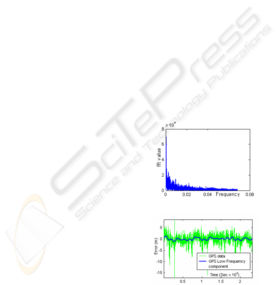
Figure 1: FFT of GPS latitude data.
Figure 2: The estimated GPS bias.
AN AUGMENTED STATE VECTOR APPROACH TO GPS-BASED LOCALIZATION
253

The analysis of longitude and latitude data
collected at a fixed location during 24 hours shows
this effect: by considering the Fast Fourier
Transform (FFT) of GPS longitude and latitude data
(the latter is shown in Figure 1), low-frequency
components can be noticed, corresponding to slow
variation of the signal in time. By estimating this
bias in GPS measurements, one can expect that – at
least in theory – the precision of GPS data should
improve, therefore making localization more
accurate. The low-frequency component of latitude
error is shown separately in Figure 2.
To estimate the bias, an augmented state vector x
is defined; x comprises both (x, y,
θ
) components of
the robot’s position, and the (x
GPS
, y
GPS
) components
of the low-frequency bias in GPS measurements.
Notice that, by separating the colored components
from Additive White Gaussian components of GPS
noise, the system gets closer to the conditions for the
Extended Kalman Filter to be applicable. When new
measurements are available (i.e., both GPS data and
the features detected by a laser rangefinders), the full
state vector can be estimated through observations.
2.2 Laser Based Localization
When moving indoor, the robot is provided with an
a-priori map of the environment; the laser-based
localization subsystem simply updates the position
by comparing this map with the features detected by
the laser rangefinder.
In particular, (Capezio, et al., 2006) describes in
details how segment-like features are extracted from
raw data and compared with the a-priori model: 1)
line extraction produces a set of lines {
j
l }; 2) the
Mahalanobis distance associated to each couple of
line (
j
l
,
i
m ) is computed (where {
i
m } is a set of
oriented segment lines that define the a-priori map);
3) for each
j
l
, the line
i
m for which such distance
is minimum is selected and fed to the EKF.
When moving outdoor, lines in the a-priori map
correspond to the external walls of buildings.
Obviously, a smaller number of features is available
outdoor, since the robot mostly traverses areas
where no buildings are present at all (especially in
the Airport scenario). However, when features are
available, they are sufficient to estimate the full state
vector, and – under some assumptions – the estimate
stays valid even when the laser cannot provide any
further information.
3 SYSTEM ARCHITECTURE
As anticipated, the proposed approach relies on the
idea of “guessing” the bias that affects GPS
measurements at a given time, by including it in the
state to be estimated. The resulting augmented state
vector is shown in Equation 1.
[
]
T
GPS GPS
xy x y
θ
=x
(1)
It includes the robot’s position and orientation
with respect to a fixed frame
w
F , and the two
components (with respect to the same frame) of the
bias in GPS measurements.
After integrating the dynamic equations of the
system through a standard Euler approximation with
step size
Δ
t=1, the system can be described with the
following finite difference Equations:
11 1
11 1
11
,,1
,,1
*cos
*sin
kk k k
kk k k
kk k
GPS k GPS k
GPSk GPSk
xx ds
yy ds
d
xx
yy
θ
θ
θθ ω
−
−−
−
−−
−−
−
−
=+
⎧
⎪
=+
⎪
⎪
=+
⎨
⎪
=
⎪
=
⎪
⎩
()
()
Ddldrd
dldrds
with
−=
+=
ω
2
(2)
The first three equations represent the discrete
approximation of the robot’s inverse kinematics, by
assuming a unicycle differential drive model. As
usual, dr and dl indicate the linear displacements of
the right and left driving wheels, and D is the
distance between them.
In the last two Equations, the dynamic of the bias
[
]
T
GPS GPS GPS
xy=x
is modeled. Notice that a
constant dynamic is assumed for
T
GPS
x
, since no
cues are available to make more accurate
hypotheses. This means that, when predicting the
new state in the time-update phase of the EKF,
T
GPS
x
is left unchanged. However, the predicted
value of
T
GPS
x
is updated whenever new
measurement are available (i.e., in the correction
phase of the EKF), thus finally producing an
estimate that varies in time, and hopefully
approximates the actual bias in GPS measurements.
The approach seems reasonable whenever a
component of the state vector changes slowly in
time with respect to the remaining components,
which is exactly the case.
When considering the remaining noise that
affects x, the process can be described as governed
by a non-linear stochastic difference Equation in the
form
(
)
1k1k1kk −−−
=
wuxx ,,f
with
5
ℜ∈x , ),0( WN=w (3)
ICINCO 2007 - International Conference on Informatics in Control, Automation and Robotics
254
where w
represents the process noise, and u
is the
driving function; i.e., the 2-dimensional vector
describing the current wheels displacements dr
and
dl (
[]
dldr
T
=u
).
For what concerns errors in the process, they are
currently modeled through a vector
[]
wgwlwr
T
=w . The first two element sums up
to dl and dr (e.g., when the left encoder returns dl,
the actual path traveled by the left wheel is dl+wl),
whereas wg represents the error made in assuming
that the bias has not changed since the last iteration
of the Filter. By assuming that w has a zero-mean
Gaussian distribution with covariance matrix W,
systematic errors in odometry due to the
approximate knowledge of the robot’s geometric
characteristics are not explicitly considered (in
theory, geometric parameters should be included in
the augmented state vector as well, as proposed in
(Martinelli, 2002)).
Observations are provided both by the GPS and,
when available, by the laser rangefinder. The
measurements provided by the GPS are a non-linear
function of the state:
⎩
⎨
⎧
+=
+=
)(*)(
)(*)(
GPSlatLATlat
GPSlatLONGlong
yyzCz
xxzCz
(4)
Where z=(z
long
, z
lat
) is a 2-dimensional vector
representing the longitude and latitude of the mobile
robot, by supposing the X-axis of F
w
lying on the
parallel passing through F
w’
s origin, and F
w’
s Y-axis
lying on the meridian. The measurement model is
not linear, mainly because the relationship between
georeferenced data (i.e., latitude and longitude) and
the estimated x- and y- coordinates varies with the
latitude itself, as a consequence of the non planarity
of the earth surface (as determined by C
LONG
(z
lat
)
and C
LAT
(z
lat
)).
For each line
j
l
observed by the laser
rangefinder, the line
i
m that best matches
j
l
can be
expressed as:
⎪
⎪
⎩
⎪
⎪
⎨
⎧
−
⎟
⎟
⎠
⎞
⎜
⎜
⎝
⎛
−
=
+
+⋅+⋅
=
−
k
i
i
ii
ikiki
b
a
z
ba
cybxa
z
θ
α
ρ
1
22
tan
(5)
where a
i
, b
i
and c
i
are the parameters characterizing
the implicit equation of
i
m ; z
ρ
and z
α
are,
respectively, the distance between the line and the
robot, and the angle between the line and the robot’s
heading.
When putting together Equations 4 and 5, the
measurement model results to be a non-linear
function of the state:
),0(),( RNwithh
kkk
=
=
vvxz (6)
Since non-AWG components of the GPS noise
are estimated in the state vector, the remaining noise
can be reasonably modeled with the vector v, a zero-
mean AWG noise with covariance matrix R.
Equation 2 can be used to compute the a-priori
state estimate at time k. Next, whenever new GPS or
laser rangefinder data are available, they are fused
with the a-priori estimate through an Extended
Kalman Filter to produce a new estimate, thus
reducing errors that are inherently present in
odometry and providing a new estimate for the GPS
bias.
Obviously, to evaluate the soundness of the
previous assertion, it is necessary to perform an
observability analysis of the system. The Kalman
theorem requires to compute the observability
matrix
4
| | ... | ( )
TTT TT
QH AH AH
⎡
⎤
=
⎣
⎦
, where A
and H are the Jacobian matrices of the partial
derivatives of f and h with respect to x (Q’s full
expression is not shown for sake of brevity). The
analysis shows that Q has full rank (and hence the
state is fully observable) only when at least two
observations
j
l
and
m
l
are available, corresponding
to non-parallel lines
i
m
and
n
m
, together with a
single GPS measurement.
Matrix A results to be:
11
11
10 sin( )00
01 cos( ) 00
00 1 00
00 0 10
00 0 01
kk
kk
ds
ds
A
θ
θ
−−
−−
−⋅
⎡
⎤
⎢
⎥
⋅
⎢
⎥
⎢
⎥
=
⎢
⎥
⎢
⎥
⎢
⎥
⎣
⎦
(7)
whereas H results to be:
22 22
22 22
11
00 0
11
000
00 0
00100
00 0
00100
LONG LONG
L
AT LAT
ii
ii ii
mm
mm mm
CC
CC
ab
ab ab
H
ab
ab ab
⎡
⎤
⎢
⎥
⎢
⎥
⎢
⎥
⎢
⎥
⎢
⎥
⎢
⎥
++
=
⎢
⎥
⎢
⎥
−
⎢
⎥
⎢
⎥
⎢
⎥
++
⎢
⎥
⎢
⎥
−
⎣
⎦
(8)
By inspecting matrix H, one could infer that the
filter is updated only when a triplet of observations
are available (i.e., two non-parallel lines and one
AN AUGMENTED STATE VECTOR APPROACH TO GPS-BASED LOCALIZATION
255

GPS measurement). However, this is assumed only
to investigate the state’s observability; during
experiments, the laser rangefinder and the GPS
returns observations asynchronously, and each
observation is used to update the state as soon as
available. The observability analysis demonstrates
that, even if each measurement is able to correct the
state only partially, the state is fully observable
when more measurements are considered in cascade.
Unfortunately, in outdoor areas it often happens
that the laser cannot detect any line mapped in the a-
priori map: since the localization algorithm relies
only on GPS data, the H matrix fed to the KF
comprises only the first two rows in Equation 8.
When this happens – as already stated - only a
subspace of the state space results to be observable;
by computing again the observability matrix Q, this
yields the result in Equation 9.
When
0
1
≠
−k
ds
, i.e. when the translational speed
of the robot is not null (Capezio, et al., 2005), the
rank of Q is 3. The rank is not full since Q’s first
column (corresponding to the x-component of the
state vector x) equals the fourth column
(corresponding to the x
GPS
-component), and Q’s
second column (i.e., the y-component) equals the
fifth column (i.e., the y
GPS
-component). On the
opposite, Q’s third column (corresponding to the
θ
-
component of x) is linearly independent from the
others.
Q’s analysis confirms the intuition that – when
no laser data are available – the subspace defined by
x+x
GPS,
y+y
GPS
, and
θ
is fully observable: the robot’s
orientation is still corrected by GPS data (when
0
1
≠
−k
ds , see also (Capezio, et al., 2005)), and the
position has a permanent error that depends on the
current estimate of the GPS bias.
⎥
⎥
⎥
⎥
⎥
⎥
⎥
⎥
⎥
⎥
⎥
⎥
⎥
⎥
⎥
⎥
⎥
⎥
⎥
⎥
⎥
⎥
⎥
⎥
⎦
⎤
⎢
⎢
⎢
⎢
⎢
⎢
⎢
⎢
⎢
⎢
⎢
⎢
⎢
⎢
⎢
⎢
⎢
⎢
⎢
⎢
⎢
⎢
⎢
⎢
⎣
⎡
⋅⋅
⋅⋅−
⋅⋅
⋅⋅−
⋅⋅
⋅⋅−
⋅⋅
⋅⋅−
=
−−
−−
−−
−−
−−
−−
−−
−−
LATkk
LAT
LAT
LONGkk
LONG
LONG
LATkk
LAT
LAT
LONGkk
LONG
LONG
LATkk
LAT
LAT
LONGkk
LONG
LONG
LATkk
LAT
LAT
LONGkk
LONG
LONG
LATLAT
LONGLONG
Cds
C
C
Cds
C
C
Cds
C
C
Cds
C
C
Cds
C
C
Cds
C
C
Cds
C
C
Cds
C
C
CC
CC
Q
/10)cos(
4
/10
0/1)sin(
4
0/1
/10)cos(
3
/10
0/1)sin(
3
0/1
/10)cos(
2
/10
0/1)sin(
2
0/1
/10)cos(
1
/10
0
/1)sin(
1
0/1
/100/10
0/100/1
11
11
11
11
11
11
11
11
θ
θ
θ
θ
θ
θ
θ
θ
(9)
In this case, the innovation due to GPS
measurements is distributed by the Kalman gain
onto x-, y-, x
GPS
, and y
GPS
components of the state
according to the current value of the state covariance
matrix P. Since a constant dynamic is assumed for
x
GPS
, and y
GPS
, corrections are adequately distributed
onto the state components only if the actual bias in
GPS changes slowly, and given that a new area
where the laser rangefinder is able to guarantee full
observablility will soon be available. This is
reasonable when assuming a cyclic patrol path for
autonomous surveillance, with periodic visits to
outdoor areas that are mapped in the a-priori model
and observable by the laser.
4 EXPERIMENTAL RESULTS
Many experiments in a realistic simulated
environment and at the Albenga Airport (Figure 6)
have been performed. Moreover, in order to test the
system under different conditions, experiments are
performed by varying the robot’ speed. The GPS
sensor is realistically simulated (data are taken from
real GPS in a 24-hours interval), as well as errors in
laser measurements and odometry.
In all the simulated tests, the robot is requested to
move along a path that is identical to the patrol
performed in Villanova d’Albenga Airport.
Furthermore, the dimension and the position of the
exterior walls of buildings considered for map-based
localization in the simulated environment
realistically emulate the Airport scenario (see Figure
3; walls are visible only in a very limited area of the
Airport). The simulated robot travels for the whole
day, performing a cyclic patrol about 500 meters
long; next, the experiment is repeated by varying the
navigation speed.
Tests have been performed in two modalities: A-
tests correspond to localization with GPS bias
estimation, and B-tests are performed without bias
estimation.
Table 1: Errors statistics in B-tests.
Nav.
Speed
(m/s).
x
e
x
σ
y
e
y
σ
ϑ
e
ϑ
σ
0.4
1.50 1.01 1.18 0.55 0.067
0.047
0.9
1.36 0.97 1.75 1.22 0.048 0.039
1.4
1.47 1.14 1.29 0.72 0.043 0.035
Table 2: Errors statistics in A-test.
Nav.
Speed
(m/s).
x
e
x
σ
y
e
y
σ
ϑ
e
ϑ
σ
0.4
1.07 1.04 1.63 1.13 0.057 0.053
0.9
0.94 0.84 0.78 0.70 0.040 0.033
1.4
0.97 0.80 1.23 1.14 0.041 0.031
ICINCO 2007 - International Conference on Informatics in Control, Automation and Robotics
256
Tables 1 and 2 summarize results. In Table 1,
results of the B-tests are shown. In this case the state
vector includes only the position and the orientation
of the robot. Table 2 shows the results of A-tests. In
both Tables,
x
e
and
y
e
represent the average error
between x- and y- components of x and the real
robot’s position (ground truth);
ϑ
e
is the average
error in the robot’s heading;
x
σ
,
y
σ
,
ϑ
σ
are the
corresponding standard deviations.
When computing the average position error as
x
err
=
22
()
x
y
Ee e+
, this yields:
- B-tests: x
err
=2.12m, x
err
=1.92m, and x
err
=2.08m
when the robot is moving at the speed of 0.4m/s,
0.9m/s, and 1.4m/s respectively
- A-tests: x
err
=1.52m,x
err
=1.34m, and x
err
=1.37m
(for 0.4m/s, 0.9m/s, and 1.4m/s).
By analyzing the data, some considerations can
be made:
- x
err
is always below 2.5m, with and without the
GPS bias Estimation.
- In the best case (1.4m/sec navigation speed),
the bias estimation reduces x
err
of about 34%.
- The improvement due to GPS bias estimation
seems to increase when the navigation speed
increase; this could be consequence of the fact that
the robot returns quicker in areas where laser-based
localization is possible.
- Standard deviations are always comparable
with averages; i.e., the error oscillates significantly
around its mean value.
- Errors in the
θ
-component are bounded, and
always below 10 degrees.
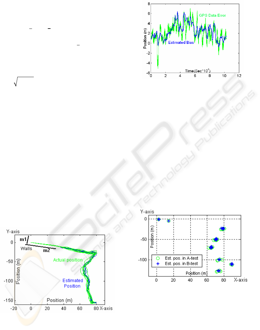
Figure 3: Test performed at 0.9 m/sec.
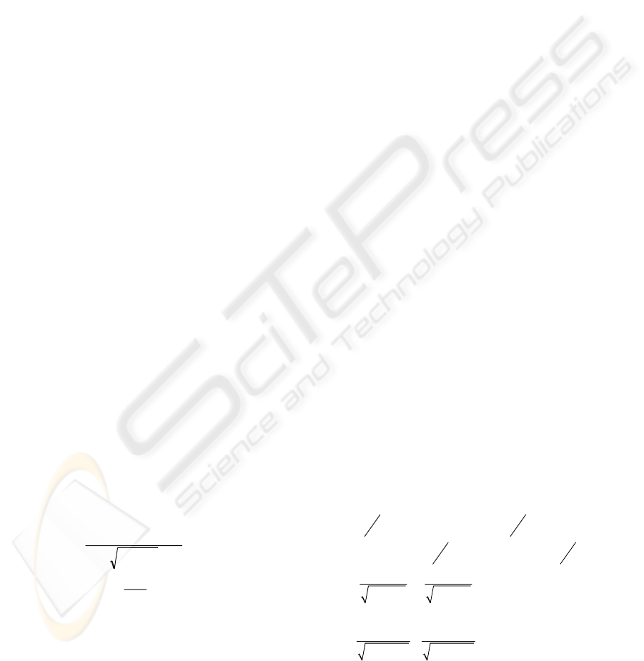
Figure 4: GPS bias estimation.
Figure 3 shows a plot of the robot’s trajectory
during an A-test 3 hours long (moving at 0.9 m/sec);
Figure 4 shows the estimated longitude bias during
such test
Real world experiments have been carried out as
well with the ANSER robot in the Albenga Airport.
During the test, the robot is manually driven at
1.0m/s along a pre-established cyclic path that is
about 500 meters long (walls are similar to Figure
3). Different A- and B-tests are been performed
(each lasting about 3 hours), by memorizing the
robot’s estimated position in a finite number of
selected places along the path.
Figure 5 shows the estimated robot’s position in 8
different places along the real path (the Figure can
be superimposed onto Figure 3 to infer where
features for laser-based localization are visible).
Figure 5: Estimated position in a real scenario.
In the real scenario, A-tests exhibit a smaller
improvement in performance with respect to
simulation. This is probably due to the fact that the
state is fully observable (and hence the GPS bias can
be correctly estimated) only when laser data are
available. However, this happens in the vicinity of
buildings (e.g., walls in Figure 3 correspond to a
hangar); unfortunately, near a building the GPS
AN AUGMENTED STATE VECTOR APPROACH TO GPS-BASED LOCALIZATION
257

signal is less precise, since the GPS satellites are
occluded by the building itself.
Figure 6: The robot ANSER at Albenga Airport.
5 CONCLUSIONS
The paper describes the localization subsystem of a
mobile robot that has been designed for night patrols
and surveillance tasks within a civilian airport. The
localization subsystem is a small – but fundamental
component – of the whole project (ANSER –
Airport Night Surveillance Expert Robot). Instead of
equipping the robot with a huge amount of
expensive sensors (and the computing power that is
adequate to deal with them), a simple approach is
chosen that relies exclusively on a non-differential
GPS unit and a laser rangefinder (i.e., inertial
sensors are absent). Laser measurements are
exploited only in some areas of the outdoor patrol
path of the robot, i.e. where it is possible detect line
features and match them against an a-priori model of
the environment. Along the rest of the path, the
robot relies on GPS-based localization. An Extended
Kalman Filter algorithm is employed to estimate an
augmented state vector comprising the robot
position and orientation, together with the low
frequency components (bias) of the GPS error.
A formal model of the whole localization
subsystem is given, including an analysis of the
system’s observability. The experiments performed
in a realistic simulated environment and at Villanova
d’Albenga Airport have confirmed the expectations,
showing that the approach reasonably improves the
localization accuracy of the system. Obviously, the
accuracy achieved is not sufficient for fine motion in
cluttered areas; however, for surveillance
applications in which the robot has to reach an area
of interest and to further investigate on the basis of
local sensor feedback, it seems appropriate.
REFERENCES
Capezio, F., Sgorbissa, A., and Zaccaria (2005), R. GPS-
based Localizzation for UGV Performing Surveillance
Patrols in Wide Outdoor Areas, In proc. of Int. Conf.
on Field and Service Robotics,
Capezio, F., Mastrogiovanni, F., Sgorbissa, A., and
Zaccaria, R. (2006), Fast Position Tracking of an
Autonomous Vehicle in Cluttered and Dynamic
Indoor Environments, In proc. of 8th International
IFAC Symposium on Robot Control
Dissanayake
, G., Sukkarieh, S., Nebot, E. and Durrant-
Whyte, H. (2001),
The aiding of a low-cost strapdown
inertial measurement unit using vehicle model
constraints for land vehicle applications, In
IEEE
Trans. on Robotics and Automation, vol. 17, Issue
5, pp. 731 – 747,
Farrell, J. A., Givargis, T. and Barth, M. (2000), Real-time
differential carrier phase GPS-aided INS, In IEEE
Trans. Contr. Syst. Technol., vol. 8, pp. 709-721.
Heath-Pastore, T., H.R. Everett, and K. Bonner (1999),
Mobile Robots for Outdoor Security Applications, In
American Nuclear Society 8th International Topical
Meeting on Robotics and Remote Systems, Pittsburgh.
Martinelli, A. (2002) The Odometry Error of a Mobile
Robot with a Synchronous Drive System. In IEEE
Trans. on Robotics and Automation, Vol 18, no. 3, pp
399-405.
Panzieri, S., Pascucci, F., and Ulivi, G. (2002), An
Outdoor Navigation System Using GPS and Inertial
Platform, IEEE Trans. on mechatronics, vol. 7, no 2
Rybski, P. E., Stoeter, S. A., Gini, M., Hougen, D. F. and
Papanikolopoulos, N P. (2002), Performance of a
Distributed Robotic System Using Shared
Communications Channels, In IEEE Trans on
Robotics and Automation, vol. 18, no.5
Saptharishi M., Oliver, C. S., Diehl, C. P., Bhat, K. S.,
Dolan, J. M., Trebi-Ollennu, A. and Khosla, P. K.
(2002), Distributed Surveillance and Reconnaissance
Using Multiple Autonomous ATVs: CyberScout, In
IEEE Trans. on Robotics and Automation, vol. 18,
no.5
Sasiadek, J. Z. and Wang, Q. (2003), Low cost automation
using INS/GPS data fusion for accurate positioning, In
Robotica, Vol. 21, pp. 255-260. Cambridge University
Press.
Schönberg, T., Ojala, M., Suomela, J., Torpo, A., and
Halme, A (1995), Positioning an autonomous off-road
vehicle by using fused DGPS and inertial navigation,
In 2nd IFAC Conference on Intelligent Autonomous
Vehicles, Espoo, pp. 226-231
Vidal, R.,, Shakernia, O., Kim, H. j., Shim, D. H. and,
Sastry, S. (2002), Probabilistic Pursuit–Evasion
Games: Theory, Implementation, and Experimental
Evaluation, In IEEE Trans. on Robotics and
Automation, vol. 18, no. 5,
Volkan, I., Sampath, K. and Sanjeev K. (2005),
Randomized Pursuit-Evasion in a Polygonal
Environment, In IEEE Trans. on robotics,vol.21, no. 5
ICINCO 2007 - International Conference on Informatics in Control, Automation and Robotics
258
