
HUMAN-SCALE VIRTUAL REALITY CATCHING
ROBOT SIMULATION
Ludovic Hamon, François-Xavier Inglese and Paul Richard
Laboratoire d’Ingénierie des Systèmes Automatisés, Université d’Angers
62 Avenue Notre Dame du Lac, 49000 Angers, France
Keywords: Virtual reality, large-scale virtual environment, human-robot interaction, catching.
Abstract: This paper presents a human-scale virtu
al reality catching robot simulation. The virtual robot catches a ball
that users throw in its workspace. User interacts with the virtual robot using a large-scale bimanual haptic
interface. This interface is used to track user’s hands movements and to display weight and inertia of the
virtual balls. Stereoscopic viewing, haptic and auditory feedbacks are provided to improve user’s immersion
and simulation realisms.
1 INTRODUCTION
Robotic researchers tried to solve the problem of
catching moving object (dynamic problem) while
basing themselves on the use a priori of the
trajectory of the object to limit the calculating time.
Most of the proposed methods generally rest on the
fo
llowing stages:
1) the detection of the ball,
2) the determination since it is in flight,
3) the follow-up and the prediction of its trajectory
4) the economic planning and the execution of a
m
ovement of interception.
Indeed, the prediction of balls trajectories in a
cont
rolled environment (no wind, etc.) is based on a
priori knowledge of characteristics of this type of
movement and, on the collection of information
about the displacement of the ball, before beginning
to make a prediction on the trajectory followed by
the object.
Virtual Reality (VR) is a computer-generated
im
mersive environment with which users have real-
time interactions that may involve visual feedback,
3D sound, haptic feedback, and even smell and taste
(Burdea, 1996 ; Richard, 1999 ; Bohm, 1992 ;
Chapin, 1992 ; Burdea, 1993 ; Sundgren, 1992 ;
Papin, 2003). By providing both multi-modal
interaction techniques and multi-sensorial
immersion, VR presents an exciting tool for
simulation of (real) human – (virtual) robot
interaction or cooperation. However, this requires a
large-scale Virtual Environments (VEs) that provide
efficient and multi-modal interaction techniques
including multi-sensorial feedbacks.
2 HUMAN-SCALE VE
Our multi-modal VE is based on the SPIDAR
interface (Figure 1). In this system, a total of 8
motors for both hands are placed surrounding the
user (Sato, 2001). Motors mounted near the screen
and behind the user; drive the strings attachments.
One end of string attachment is wrapped around a
pulley driven by a DC motor and the other is
connected to the user’s hand.
By controlling the tension and length of each string,
t
he SPIDAR-H generates an appropriate force using
four string attachments connected to a hand
attachment. Since it is a string-based system, it has a
transparent property so that the user can easily see
the virtual world.
It also provides a space where the user can freely
m
ove around. The string attachments are soft, so
there is no risk of the user hurting himself if he
would get entangled in the strings. This human-scale
33
Hamon L., Inglese F. and Richard P. (2007).
HUMAN-SCALE VIRTUAL REALITY CATCHING ROBOT SIMULATION.
In Proceedings of the Fourth International Conference on Informatics in Control, Automation and Robotics, pages 33-38
DOI: 10.5220/0001626900330038
Copyright
c
SciTePress
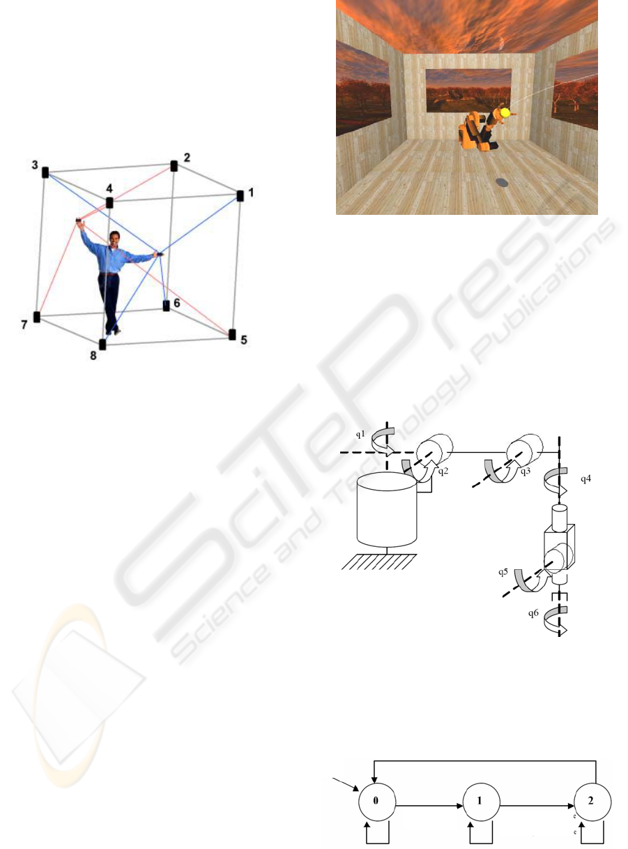
haptic device allows the user to manipulate virtual
objects and to naturally convey object physical
properties to the user’s body. Stereoscopic images
are displayed on a back-projected large screen (2m x
2,5m) and viewed using polarized glasses. A 5.1
immersive sound system is used for simulation
realism, auditory feedback and sensorial immersion.
Olfactory information can be provided using a
battery of olfactory displays.
Figure 1: Workspace of the SPIDAR device.
3 CATCHING SIMULATION
3.1 Virtual Room
The virtual room in which simulation takes place is a
right-angled parallelepiped which consists of a
ground, a left wall and a right wall. The ceiling is
left open. A wood texture was added on each face to
increase the depth perception, as well as the ball
shadow.
This virtual room contains objects such as a
virtual ball, virtual hands (right and left), and a
virtual robot (a Kuka KR6).
All calculation are made in cartesian co-ordinates X,
Y, Z, according to an orthonormed reference frame
whose origin O is located at the middle of the floor.
The Z axis is directed towards the user. The Y axis
is directed upwards. The X axis is directed towards
the right compared to the user view.
Figure 2: Snapshot of the robot reaching for the ball.
3.2 Robot Modelling
The robot chosen here is Kuka KR6 model. It is an
arm manipulator with 6 degrees of freedom, having
only rotoids axes. It is placed at the bottom of the
virtual room. Each part of the model was modelled
in Discreet 3D Studio Max 7.0 and then imported
into OpenGL. The robot consists of 6 rotoïds axes
whose angles are respectively q1, q2, q3, q4, q5, q6.
Figure 3: Illustration of the parameters used for the
geometrical modelling of the Kuka KR6 robot.
To animate each robot part, elementary geometrical
operations such as translations and rotations around
the frame reference is used.
Ball
g
ras
p
ed b
y
human
Initial
state
Ball caught
by
robot
Ball released
by robot
Figure 4: Finite state machine of the robot.
ICINCO 2007 - International Conference on Informatics in Control, Automation and Robotics
34
The virtual robot is subjected to the finite state
machine given in figure 4. The various states are
defined as follows:
State 0: the robot tries to catch the ball if in its
workspace.
At the beginning of simulation, the robot waits until
the ball is seized by the human operator, via the
virtual hand, or till an external force is generated on
the ball, to return to state 0.
State 1: the robot catches the ball if in state 0.
State 2: the robot releases the ball automatically,
after a certain amount of time, and returns in its
initial configuration.
The robot waits until the ball is grasped by the user
(using one of the virtual hand) or till an external
force is generated on the ball to return to state 0.
Once the ball is caught, the robot automatically
drops the ball and the simulation is reinitialised in its
initial configuration.
The virtual ball is represented by a sphere and has a
given mass "m", a given radius "R" and a given
velocity "Vb" (or a Velocity Vector).
Assimilated to a single point which is the centre of
the sphere, the ball is animated according to the
fundamental law of dynamics: F=mA, i.e. the sum of
the external forces F applied to the ball, is equal to
the mass of the ball multiplied by acceleration.
Thus, the animation engine of the ball uses the
following formulas:
Force = truncate(Force, max_force)
Acceleration = Force/m
Velocity = Velocity + Acceleration
Velocity = truncate(Velocity, max_velocity)
Position = Position + Velocity
Or Force=(Fx,Fy,Fz) , Acceleration=(Ax,Ay,Az) ,
Velocity = (Vx , Vy , Vz) ,
Position (Px , Py , Pz)
"max_force" is defined by the developer. It
represents the maximum force that could be applied
to the ball. Similarly, "max_velocity" represents the
maximum velocity that could be set to the ball.
Thus one truncates the force by "max_force" and
velocity by "max_velocity" to avoid reaching a force
or velocity of oversized magnitudes.
In this way, a new position of the ball could be
calculated at any time (more precisely according to
the main loop of the simulation), when the ball is
free (not caught by the robot or grasped by the user).
The ball is subjected to the finite state machine
given in fig.5.
Left hand grasp
Ball
caught
Figure 5: Finite state machine of the ball.
The various states are defined as follows:
State 0: the ball is free and is thus subjected to the
animation engine described before.
State 1: the ball is caught by the left hand. The
position of the ball is therefore directly linked to the
position of this hand.
State 2: the ball is caught by the right hand. The
position of the ball is therefore directly linked to the
position of this hand.
State 3: the ball is released by the left hand. The
position of the ball is no more established by the
hand, but rather by the animation engine. The
external Forces vector is equal, at this moment, to
the hand velocity vector Vmx, Vmy, Vmz.
State 4: the ball is released by the right hand. The
position of the ball is no more established by the
hand, but rather by the animation engine. The
external Forces vector is equal, at this moment, to
the hand velocity vector Vmx, Vmy, Vmz.
State 5: the ball is caught by the robot. The position
of the ball is no more established by the animation
engine, but rather is a function of the robot gripper
position.
State 6: the ball lies on the ground or closed to the
ground. The Velocity vector magnitude is close to
zero. The ball automatically moves to state 6, which
is the end state and is immobilized on the ground.
6
Gripper
r
e
l
e
a
se
Left hand
release
Left hand
grasp
Right hand
grasp
Right hand
release
External
force
Right hand grasp
HUMAN-SCALE VIRTUAL REALITY CATCHING ROBOT SIMULATION
35
User’s hands position is tracked using the SPIDAR
device.
A gain parameter between the user hand movements
and the virtual hands can be introduced in order to
enable him to increase his workspace. For example,
it can be tuned so that the user can reach any
location of the virtual room without moving too far
from the centre of the SPIDAR frame of reference.
The closing of the virtual hand is carried out by the
closing of a 5dt wireless data glove worn by the user
(http://www.5dt.com). This could also be achieved
using wireless mousses integrated to the SPIDAR
device.
Each virtual hand is subjected to the finite state
machine given in fig.6.
The different states are
defined as follows:
State 0: the left (respectively right) hand is open: it
cannot grasp the ball.
State 1: the left (respectively right) hand is closed:
it can grasp the ball if the latter is in state 0 or 6 or 1
(respectively 2).
Figure 6: Finite state machine for both hands.
To do the ball grasping, a sphere of detection is
used. Its size is defined by the designer and it is
invisible during simulation. If the ball and the sphere
are in contact, it is considered that the ball is seized,
and the position of the ball is readjusted according to
the hand.
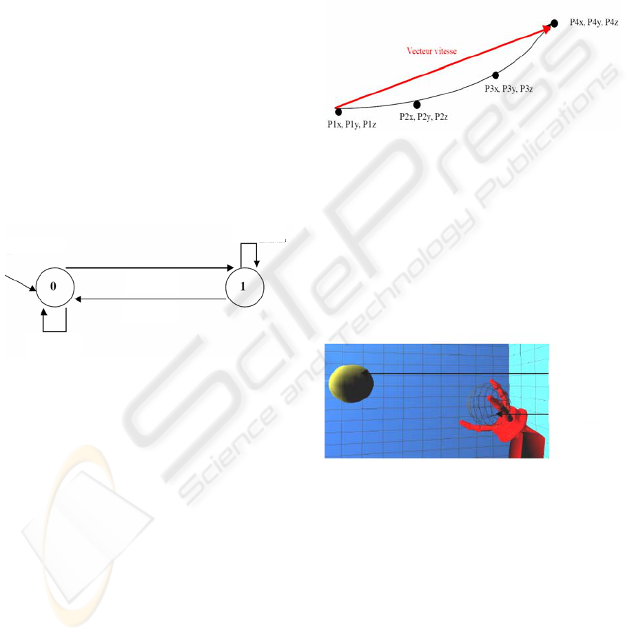
3.3 Ball Launching
The virtual ball is thrown by the human operator,
which can grasp and move it using the virtual hands.
Once the ball is grasped, a method to launch the ball,
corresponding to the animation engine, is proposed
and validated. This method allows efficient velocity
transfer of a user hand to the virtual ball.
To do this, hand velocity must be calculated. Thus
an array of size S (S being defined by the designer),
is created and is used to record the hand position at
each loop cycle of the main program loop.
Fig. 7 illustrates an example with an array of size S
= 4. At the initialisation, the array is empty.
This method is easy to implement and is not CPU-
time consuming. It gives good results to reproduce
realistic "launched balls". However, this requires an
optimisation of the size (S) of the array.
Figure 7: Illustration of the method proposed to efficiently
launch the virtual ball with an array size S=4.
3.4 Ball Catching
Ball catching is achieved using a detection sphere of
predefined size and invisible during the simulation.
If the ball and the sphere are in contact, it is
considered that the ball is caught. Then the ball
position is readjusted according to the robot gripper
position.
Mouse click on
Mouse click on
Initial
state
Mouse click off
Mouse click off
Virtual
ball
Detection
sphere
Figure 8: Illustration of the algorithm used for ball
catching by the robot gripper.
This requires knowing both the cartesian position of
the gripper according to the 6 angles q1, q2, q3, q4,
q5, q6 and the dimensions of each part of the robot.
The gripper is subjected to the finite state machine
illustrated on fig. 9.
ICINCO 2007 - International Conference on Informatics in Control, Automation and Robotics
36
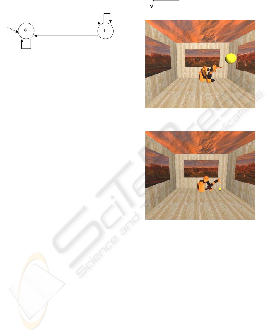
Figure 9: Finite state machine for the gripper.
The states of the gripper are defined as follows:
State 0: the gripper is open; the grip is open when
the ball is not caught.
State 1: the gripper is closed; the grip is closed
when the ball is caught.
In order for the robot to catch the ball, it is
necessary to know: (1) the cartesian position of the
gripper at any time according to the 6 angles q1, q2,
q3, q4, q5, and q6 of the robot and, (2) the Cartesian
space reached by the robot (workspace). This is
given by the direct geometrical model defined by
X=f(Q), with X=(x,y,z) and Q=(q1,q2,q3,q4,q5,q6).
It is also necessary to know the value of the 6
angles of the robot, according to the Cartesian
position of the gripper (X, Y, Z). The inverse
geometrical model can obtain these.
Thus, it can be resolved by determining the joint
coordinates Q making it possible to obtain a desired
location for the gripper specified by the space
coordinates.
Here, we are confronted with a system of 3
equations with 6 unknown variables. To solve this
system, the method proposed by Paul (1981) was
used. This method allows obtaining the whole
solutions set, when they exist.
In our simulation, the robot always faces the
ball.
However, it will carry out a catching movement
towards the ball only if the latter is in its workspace,
defined by the whole set of points in the Cartesian
space that the robot gripper can reach.
Under the hypotheses that the robot can reach
all the points of its workspace at any time, and that
there is no constraint on the rotation angles of the
joint, the workspace of the robot is a TORE defined
by equation 3.
(
) z² x²( +
- A )² + y² = R
2
(3)
Ball catched
Initial
state
Ball catched
Ball released
Ball released
Figure 10: Snapshot of the robot oriented towards the ball.
Figure 11: Snapshot of the robot realising the ball.
4 CONCLUSION
We presented a human-scale virtual reality catching
robot simulation.. The user interacts with a virtual
robot by throwing virtual balls towards it, using a
large-scale bimanual haptic interface. The interface
is used to track user’s hands movements and to
display various aspects of force feedback associated
mainly with contact, weight, and inertia. We
presented the robot modelling, as well as the ball
launching and catching procedures.
REFERENCES
Inglese, F.-X., Lucidarme, Ph., Richard, P., Ferrier, J.-L.,
2005. PREVISE : A Human-Scale Virtual
HUMAN-SCALE VIRTUAL REALITY CATCHING ROBOT SIMULATION
37

Environment with Haptic Feedback. In Proceedings of
ICINCO 2005. Barcelona, Spain, pp. 140-145.
Burdea, G. , Coiffet, Ph.., Richard, P., 1996. Integration of
multi-modal I/Os for Virtual Environments. In
International Journal of Human-Computer Interaction
(IJHCI), Special Issue on Human-Virtual Environment
Interaction. March, (1), pp. 5-24.
Richard, P., Coiffet, Ph., 1999. Dextrous haptic interaction
in Virtual Environments: human performance
evaluation. In Proceedings of the 8th IEEE
International Workshop on Robot and Human
Interaction. October 27-29, Pisa, Italy, pp. 315-320.
Bohm, K., Hubner, K., Vaanaen, W., 1992. GIVEN:
Gesture driven Interactions in Virtual Environments.
A Toolkit Approach to 3D Interactions. In
Proceedings of Interfaces to Real and Virtual Worlds.
Montpellier, France, March, pp. 243-254.
Chapin, W., Foster, S., 1992. Virtual Environment Display
for a 3D Audio Room Simulation. In Proceedings of
SPIE Stereoscopic Display and Applications. Vol.12.
Burdea, G., Gomez, D., Langrana, N., 1993. Distributed
Virtual Force Feedback. In Proceedings of IEEE
Workshop on Force Display in Virtual Environments
and its Application to Robotic Teleoperation. Atlanta,
May 2.
Sundgren, H., Winquist, F., Lundstrom, I., 1992. Artificial
Olfactory System Based on Field Effect Devices. In
Proceedings of Interfaces to Real and Virtual World.
Montpellier, France, pp. 463-472, March.
Papin, J.-P., Bouallagui, M., Ouali, A., Richard, P., Tijou,
A., Poisson, P., Bartoli, W., 2003. DIODE: Smell-
diffusion in real and virtual environments. In
Proceedings of the 5th International Conference on
Virtual Reality. Laval, France, pp.113-117, May 14-
17.
Bowman, D.A., Kruijff, E., LaViola, J.J., Poupyrev, I.,
2004. 3D User Interfaces: Theory and Practice.
Addison Wesley / Pearson Education.
Richard, P., Birebent, G., Burdea, G., Gomez, D.,
Langrana, N., Coiffet, Ph., 1996. Effect of frame rate
and force feedback on virtual objects manipulation. In
Presence - Teleoperators and Virtual Environments.
MIT Press, 15, pp. 95-108.
Bouguila, L., Ishii, M., Sato, M. , 2000. A Large
Workspace Haptic Device For Human-Scale Virtual
Environments. In Proceedings of the Workshop on
Haptic Human-Computer Interaction. Scotland.
Sato, M., 2001. Evolution of SPIDAR, In Proceedings of
the 3rd International Virtual Reality Conference.
Laval, May, France.
Richard, P., 1981. Robot Manipulators--Mathematics,
Programming, and Control, MIT Press.
ICINCO 2007 - International Conference on Informatics in Control, Automation and Robotics
38
