
THE TELE-ECHOGRAPHY MEDICAL ROBOT OTELO2
Teleoperated with a Multi Level Architecture using Trinomial Protocol
Gwenaël Charron
(1)
, Aïcha Fonte
(1)
, Pierre Vieyres
(1)
Philippe Fraisse
(2)
, Lama Al Bassit
(1)
and Cyril Novales
(1)
(1)
Laboratoire Vision & Robotique, University of Orleans, Bourges, France
(2)
Laboratoire d’Informatique, de Robotique et de Microélectronique de Montpellier, University of Montpellier II
Montpellier, France
Keywords: Teleoperated system, Telerobotics, OTELO medical robot, Tele-echography, Multi level archecture.
Abstract: This paper presents a novel architecture applied
to a mobile teleoperated medical robotic system: OTELO2
(MObile Tele-Echography using an Ultra-Light RObot); OTELO2 performs a tele-echography at a distance
for the benefit of medically isolated sites. First, this paper presents an overview of the OTELO2
teleoperated system. Then, it describes the modular control architecture used and the integration of the
teleoperated layer on this multi level architecture. Finally, it presents the communication links used to
control this system, as well as some experimental results.
1 INTRODUCTION
Telerobotics and teleoperation have currently a very
important role to play in the medical field especially
in non invasive medical application (i.e. tele-
echography) needed by the patients living in isolated
sites with reduced medical facilities. The aim of the
OTELO2 system is to provide people with the best
medical examination conditions and thus to have the
best diagnostic as possible.
Based on the concept of a mechanical probe
h
older, OTELO2 is a teleoperated robotic
manipulator arm. Teleoperated systems are exposed
to possible instability due to the transmission delay
of the communication link and to the need of remote
safety and maintenance of the robot. The goal of the
proposed combined approach, i.e. to use a specific
protocol to reduce data loss and to implement a
modular architecture to enhance the tele-echography
system, is to favor the overall remote medical act for
the benefit of the patients.
To control teleoperated system, lots of
architectures
have been proposed. The
“Subsumption Architecture” (Brooks, 1986) is
composed of parallel different levels which process
information supplied by the sensors in order to
determine the control to be sent to actuators. The
LAAS architecture (Alami, 1998) is made up of
three levels: decisional, executive and functional. Its
goal is to homogenize the whole mobile robotics
developments and to be able to re-use already
designed modules. The AuRA architecture (Arkin,
1998) is made up of two parts (reactive and
deliberate), each using distinct method to solve
problems. The reactive part is based on sensors and
the deliberate part uses artificial intelligence method
contains a mission planner, a spatial reasoner and
plan sequencer. The OTELO2 architecture relies on
the concept of levels initially developed by Brooks
and which appear in architectures proposed by
AuRA or LAAS. The originality of this architecture
is to decompose the control in multi-levels which
allows to decompose in clear way the different
functions realized and also to decompose each level
in several blocks which allow to retail and to
separate the connections with the sensors and the
actuators.
A description of the teleoperated robotic system,
i
ncluding the “expert” and the “patient” station, is
given in the first section. The second section
presents the architecture developed to control the
robot. The next section presents the communication
links between the two stations composing the system
and the protocol used to control the robot. The last
section presents some experimental result obtained
during a teleoperation between Bourges (France)
and Montpellier (France).
52
Charron G., Fonte A., Vieyres P., Fraisse P., Al Bassit L. and Novales C. (2007).
THE TELE-ECHOGRAPHY MEDICAL ROBOT OTELO2 - Teleoperated with a Multi Level Architecture using Trinomial Protocol.
In Proceedings of the Fourth International Conference on Informatics in Control, Automation and Robotics, pages 52-58
DOI: 10.5220/0001627600520058
Copyright
c
SciTePress
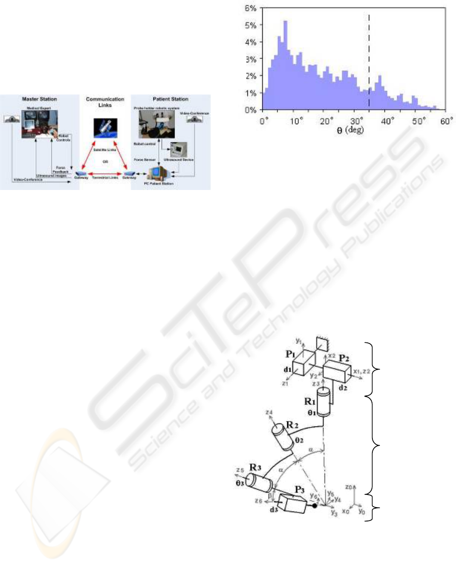
2 THE OTELO2 SYSTEM
OTELO2 is a teleoperated robotic prototype system
composed of an “expert” station and a “patient”
station. A communication network (e.g. terrestrial or
satellite) allows data transmission (i.e. ultrasound
images, robot controls, haptic feedback and ambient
images) between the two stations (
Figure 1).
Figure 1: The OTELO2 teleoperation chain.
2.1 The “Patient” Station
The “patient” station is located near the patient at a
medically isolated site or in a secondary hospital. It
includes a portable echograph device allowing
ultrasound frames acquisition and the hardware
system for the control of the probe holder robot.
The results of a previous study (Al Bassit, 2003),
on the medical gesture performed by a specialist
during an abdominal echography, gave the
mechanical constraints and characteristics of the
robot work space with respect to the tele-echography
medical application. The probe must have a
spherical displacement around a contact point of the
probe with the patient’s skin. Displacement
amplitudes (
Figure 2) are characterized by: a
maximal probe inclination of 60° with respect to the
normal of the skin plan. (larger inclination is
considered useless by the medical expert); a minimal
inclination of 35° is necessary, as well as a full
rotation of 360° around the probe symmetric axis are
needed to fulfill users’ requirements. Finally, a
translation along the probe axis is necessary to
obtain quality ultrasound images and maintain a
continuous contact between the probe and the
patient’s skin. For safety functioning, patient
comfort and force control, this displacement
amplitude is limited to the interval [-30mm, 10mm].
Hence, the maximal admissible force of the probe on
the skin does not exceed 20 Newton.
(
t
ime)
Figure 2: Histogram of inclination angle θ of the probe
axis during an abdominal ultrasound examination.
The OTELO2 robot prototype was developed by
the Laboratory of Vision and Robotic (LVR) in
collaboration with European project partners in
order to answer the previously mentioned criteria.
OTELO2 is a serial six DOF (Degree Of Freedom)
probe holder system; it includes a positioning
module (with two prismatic articulations, P1 and P2,
with perpendicular axis), a spherical module with
distant rotation center (with three revolute pairs R1,
R2 and R3, the R1-R2 and R2-R3 angles are equal to
α) and a translation along the probe axis (P3, the
R3-P3 angle is equal to β) allowing, for a given
orientation, to modify the probe/skin contact force
(
Figure 3).
Positioning
Module
Orientation
Module
End Effecto
r
Su
pp
ort s
y
ste
m
Figure 3: Kinematics diagram of OTELO2 robot
prototype.
The α and β angles, respectively 27,5° and 10°,
allow a probe maximal inclination of 65° which
complies with the medical requirements. The
positioning module allows a probe displacement
with maximal amplitude of ±25mm for each axis
and offers two DOF to search for an organ. The
THE TELE-ECHOGRAPHY MEDICAL ROBOT OTELO2 - Teleoperated with a Multi Level Architecture using
Trinomial Protocol
53
3 THE OTELO2 SYSTEM
CONTROL ARCHITECTURE
translation amplitude along the probe axis is about
40mm. This axis is coupled with a force sensor
giving the force applied by the ultrasonic probe on
the patient’s skin and enabling its control. The force
is transmitted back to the “expert” station in order to
ensure the most realistic examination conditions for
the medical expert. Finally, depending on the
examination type (e.g. ObGyn, Abdominal), various
types of manufactured probe can be attached to the
end effector of the support system.
For the teleoperated robot and in order to integrate
teleoperation layer, it was decided to set up a layered
architecture (Novales, 2006). It is a multi level
architecture where each level corresponds to a
decision/perception loop.
In this section, we present the control
architecture of the OTELO2 robot, and the global
architecture of the OTELO2 system is described
with the two MMI (Man Machine Interface)
developed to control the system.
The end effector of the remote robot moves the
ultrasound probe in order to reproduce the expert
gestures which are being analyzed by a dedicated
input device (
Figure 4). Images coming from the
ultrasound system are compressed and sent to the
“expert” station, using the H263 protocol, and
analyzed by the specialist.
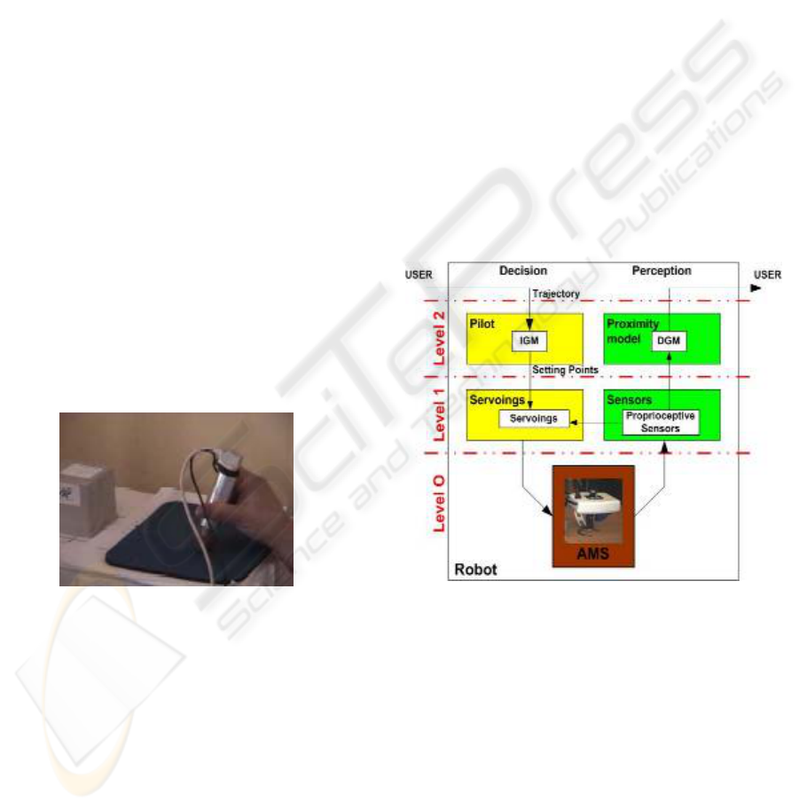
3.1 The “Patient” Architecture
The control architecture of the OTELO2 robot
prototype is a three level architecture partitioned in
two parts, namely the “Perception” and the
“Decision” parts. Each one of these levels
correspond to either a software layer or a hardware
layer (
Figure 5).
2.2 The “Expert” Station
The “expert” station is located in a main hospital
center and is operated by a medical expert. Based on
the received ultrasound images, the expert uses a
pseudo haptic input device (
Figure 4) to control the
positions and orientations of the remote ultrasound
probe. A videoconferencing system between the two
stations allows the medical expert to communicate
with the patient, to give instruction to the assistant
holding the robot, and to check the good positioning
of the robot on the patient’s body.
Figure 4: The pseudo haptic input device used to control
the orientations and positions of the remote robot.
Figure 5: The layered control architecture of OTELO2
robot.
To control of the teleoperated echography robot
was supervised under a novel multi layered and
modular architecture. This hardware and software
structure was added with specific communication
protocols used to control the robot on Internet
network. The following section presents the
proposed control architecture and its layout. It is
followed by the description of the protocol used for
data transmission for the robot control.
Level 0 represents the Articulated Mechanical
System (AMS); it contains the input/output direct
interface between the physic world and the robot.
This level receives physical data necessary to its
actuators and sends information to the sensors at
level 1.
Level 1 of the decision part corresponds to the
servoings level; it determines the physics data, to be
addressed to level 0, from the setting points imposed
directly by the upper level.
ICINCO 2007 - International Conference on Informatics in Control, Automation and Robotics
54
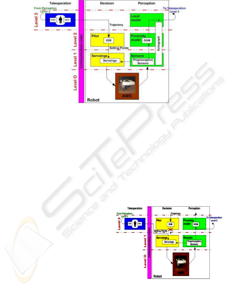
Figure 6: The global architecture of OTELO2 teleoperated system.
The level 1 perception part receives the
information supplied by the sensors, and it translates
this information to the upper level and to the
servoings module. This level ensures the articular
servoings with six modules in each part,
corresponding to the six axes and associated sensors
of the robot.
Finally, Level 2 decision part corresponds to the
pilot level; it generates the articular setting points to
the lower level from a trajectory (position and
orientation of the probe) supplied by the user. The
pilot block uses the IGM (Inverse Geometric Model)
to generate the setting points taking into account the
physical constraints of the system. The level 2
perception part presents a proximity model using a
DGM (Direct Geometric Model) to transmit the
robot current positions and orientations to the user.
We can note, for our application, that there is not a
direct feedback loop on this second level. The
control loop is accounted for through the distant
human teleoperator.
Perception and Decision parts constitute the so-
called autonomous part of the robot. A third part,
called the teleoperation, is added to the two previous
one in the framework of a teleoperated system.
3.2 The Global Architecture
The global architecture includes the Perception,
Decision and Teleoperation parts. Each level of the
teleoperation part receives the data stemming off the
level corresponding of the perception part and can a
by-pass the corresponding level of the decision part
in order to generate the controls for the lower level.
In the OTELO2 system global architecture
(
Figure 6), the teleoperation level is located at level
3; it corresponds to the navigation level. This part
generates the trajectories which are executed by the
robot and are sent to the pilot of the level 2 decision
part. Moreover, the echograph device delivers
information of a high level (ultrasound images) from
its own sensors. Thus, this teleoperation level
receives information from the level 3 perception part
including the robot positions and orientations, and
the ultrasound images coming from the ultrasound
probe.
This global architecture offers the possibility of
lower control level required for remote maintenance
and testing of the teleoperated robot (
Figure 7).
Figure 7: The level 2 teleoperation architecture.
This teleoperation level can control the robot
directly, sending articulars setting points. Hence, the
user is able to directly and remotely control the robot
THE TELE-ECHOGRAPHY MEDICAL ROBOT OTELO2 - Teleoperated with a Multi Level Architecture using
Trinomial Protocol
55
actuators and is able to detect which of the actuators
has a malfunction.
These two teleoperation levels are associated
with two MMI allowing an efficient and flexible
utilisation of the remote robot.
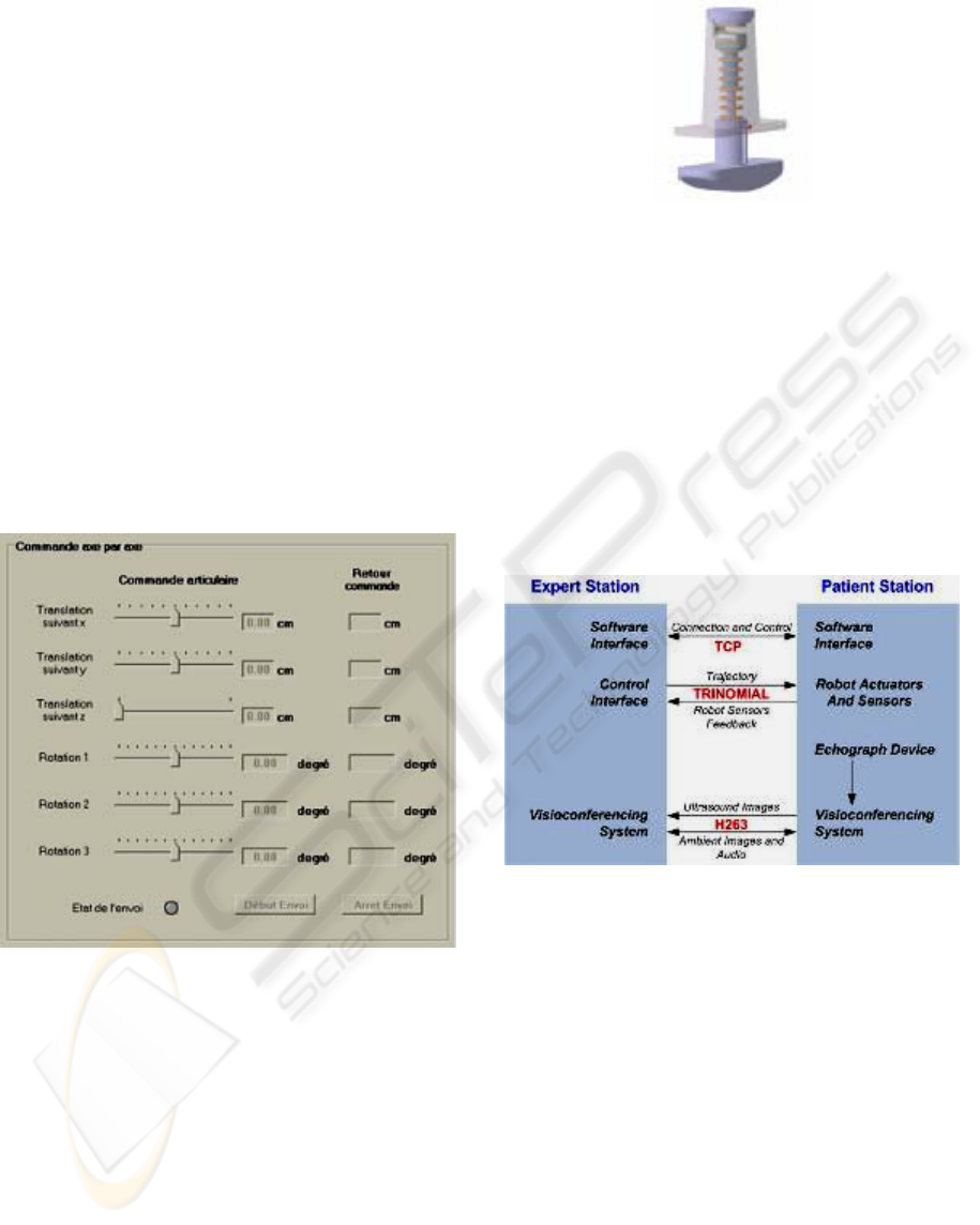
3.3 Man Machine Interface
With the intention to support the medical expert and
in order to ensure the best possible diagnostic, two
MMI have been developed for the “expert” station.
The first MMI is a graphical interface provided
to the medical expert to visualize the ultrasound
images and to choose the appropriate teleoperation
level. According to the teleoperation type, the
medical expert can control the robot in two different
ways. When the expert controls the robot with the
high teleoperation level, he/she uses the pseudo
haptic input device (second MMI). When the expert
controls the robot at a lower teleoperation level,
he/she uses a visual interface (
Figure 8) to control
each individual actuator.
Figure 8: Level 2 teleoperation control interface.
The second MMI is a pseudo haptic interface
that resembles an ultrasonic probe. The expert uses
the pseudo haptic input device equipped with a six
DOF localization magnetic sensor giving positions
and orientations.
The pseudo haptic input device (Poisson, 2003)
holds a constant stiffness coefficient which provides
the medical expert with a rendering of the patients’
body compliance and the force applied by the probe
on the patients’ body. The
Figure 9 shows the design
of the
pseudo haptic input device prototype; it includes
a force sensor to measure the force applied by the
medical expert in accordance with principal axis of
the probe.
Figure 9: Design of the pseudo haptic input device
prototype.
4 THE COMMUNICATION LINK
AND DATA TRANSMISSION
The communication between the two stations can be
carried out using different communication networks
such as satellite, ISDN lines (Integrated Services
Digital Network) or the Internet. To perform the
robotic tele-echography, three communications
protocols are used to transmit all data between the
two stations (
Figure 10).
Figure 10: Data Flow representation between the expert
and the patient station and selected protocol.
The TCP (Transmission Control Protocol) is an
oriented connection protocol. It is used to establish
the connection between the two stations, and allows
a continuous control of the connection state between
the two stations.
To transfer the robot controls, a reliable
communication protocol with small transmission
delays is needed. Two protocols were firstly
considered: the TCP and UDP protocols. TCP
ensures reliability in the exchange but can block the
communication in case of data loss. UDP protocol
(User Datagram Protocol) due to its simplicity
generates small transmission delays. However it
cannot adapt its flow to the network bandwidth and
cannot confirm that data have arrived to the distant
ICINCO 2007 - International Conference on Informatics in Control, Automation and Robotics
56
site. It was then decided to use a compromise
between these two protocols: the trinomial
(Xiaoping Liu, 2003). It allows the network not to
remain blocked in case of data loss as there is no
reemission of the lost data. However, contrary to
UDP, trinomial takes into account the transmission
delay (i.e. the received data acknowledgement)
which allows a modulation of the flow and thus a
limitation of the network saturation. In our case, the
“expert” station sends the trajectories to the
“patient” station using this protocol, and it receives
the sensors feedback through the reception of the
data acknowledgement.
Finally, a connection is established in order to
transmit the ambient images or the ultrasound
images to the “expert” station via the
videoconferencing system. A bandwidth of 256-384
kbps is required depending on the quality of
ultrasonic device to offer the best image quality to
the “expert” station.
5 RESULTS
To validate the control architecture and to test the
efficiency of our control transmission protocol, a set
of tests was performed during a teleoperation
between the LIRMM in Montpellier and the LVR in
Bourges using the Ethernet RENATER-4 public
network; this network provides a flow of about
30Mbit/s.
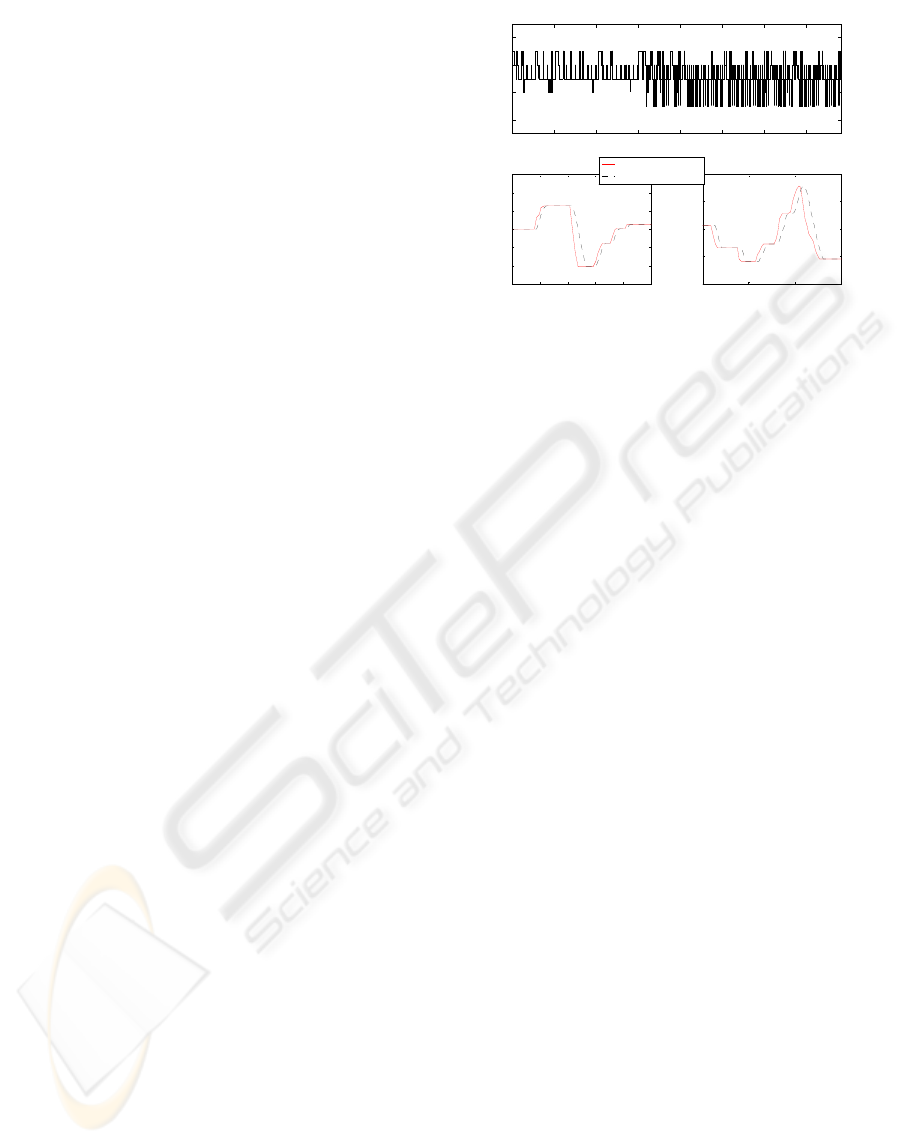
These results show Round-Trip Time (RTT)
between Montpellier and Bourges (
Figure 11 (a)),
which corresponds to the delays measured between
the data transmission and the acknowledgement
reception of this data. The RTT varies between 7
and 11 ms proving the efficiency of the chosen data
transmission protocol.
Moreover, these results show delays obtained
between sending out the control data and the robot
position feedback (
Figure 11 (b) and (c)) (which
include transmission and the time of the servoings).
We can see that the system needs approximately 20
ms to reach the desired position.
These results are quite satisfactory and allow us
to perform in real time examination in very good
conditions without disturbing the rendering of the
distant environment to the expert (Arbeille, 2004).
0 100 200 300 400 500 600 700
6
8
10
12
Data sent
Time (ms)
(a)
3600 3700 3800 3900 4000 4100
-150
-100
-50
0
50
100
150
Time (ms)
Angle (°)
(b)
5600 5800 6000 6200
-200
-100
0
100
200
Time (ms)
Angle (°)
(c)
Desired Control
Robot Feedback
Figure 11: Result during test between Montpellier and
Bourges (a) represents the data Round Trip Time, (b) and
(c) represent respectively the second and the third axis
servoing time delay.
6 PERSPECTIVES
Some improvements (transmission and architectural)
have to be considered to provide the medical expert
with better examination conditions thus ensuring the
best diagnostic as possible.
The communication link (Internet, ISDN,
satellite…) used to emit data from the expert station
induces transmission delays that can provoke
aperiodic data reception and even destabilize the
closed loop global system. This can disturb the
medical expert medical act when this delay varies
too strongly. To avoid that, it is possible to use a
FIFO regulator type (Lelevé, 2000) to synchronise
the data reception, and thus to provide the expert
with a more steady date flow and to adapt more
easily his control of the distant robot to the
transmission delays.
It is also possible to add an autonomous mode
coupled with a level 4 of the teleoperation part, with
the intention to realize a full echography of an organ
allowing a 3D reconstruction. Thus, the medical
expert would select the organ to be investigated and
the robot would fallow all trajectories needed to
supply the 3D reconstruction wanted by the medical
expert. The virtual diagnosis by the expert is made
from the 3D reconstruction.
7 CONCLUSION
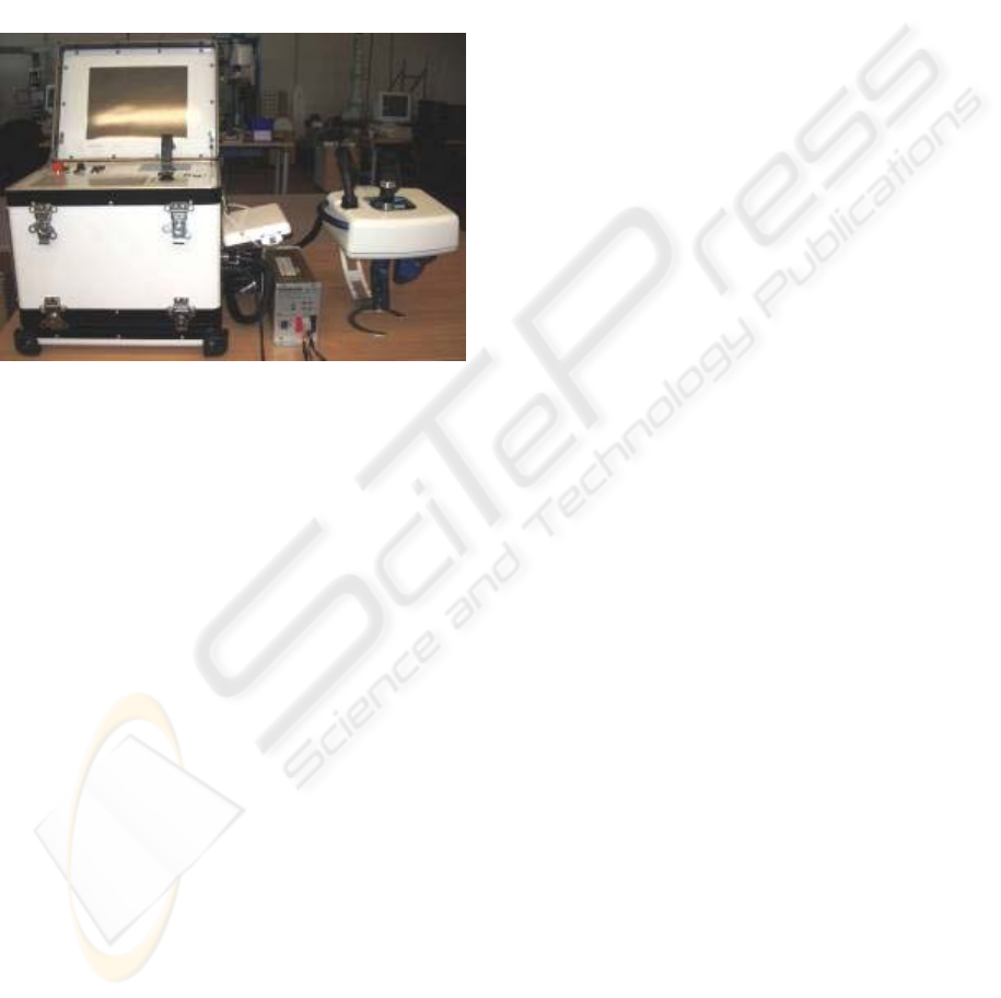
From a mechanical view point, the OTELO2
prototype robot (
Figure 12) corresponds to the criteria
imposed by the medical gesture study and experts’
requirement; it thus ensures identical examination
THE TELE-ECHOGRAPHY MEDICAL ROBOT OTELO2 - Teleoperated with a Multi Level Architecture using
Trinomial Protocol
57
conditions than to the standard ultrasound one. The
modular architecture developed to control it permits
easy insertion of new control modules whenever
upgrade of the control architecture is needed.
Finally, the communication protocol used to control
the robot allows small transmission delays and offers
moreover adaptability to the network condition.
The experimental results collected during the
teleoperation between Montpellier and Bourges
show the viability of the tele-echograph system and
provided good clinical results.
Figure 12: The OTELO2 prototype system.
REFERENCES
Alami, R., Chatila, R., Fleury, S., Ghallab M., and Ingrand
F., 1998. An architecture for autonomy. The
International Journal of Robotics Research, Special
Issue on Integrated Architectures for Robot Control
and Programming, vol. 17, no 4, pp. 315-337.
Al Bassit, L., Poisson, G., Vieyres, P., 2003. Kinematics of
a Dedicated 6DOF Robot for Tele-Echography,
Proceedings of the 11
th
International Conference on
Advanced Robotics, ICAR 2003, pp. 906-910,
Portugal.
Arbeille, Ph., Ayoub, J., Vieyres, P., Porcher, M., Boulay,
J., Moreau, V., Poisson, G., 2004. Echographic
diagnostic on a patient far from the hospital using a
teleoperated robotic arm and the satellite
communications. Conference on Tele-Health and
Satellites, 8-9 July. Rabat, Marocco.
Arkin, R.C, 1998. Behavior-based Robotics. MIT Press.
Brooks, R.A., 1986. A robust layered control system for a
mobile robot. IEEE Journal of Robotics and
Automation, vol. 2, n°. 1, pp. 14–23.
Camarinha-Matos, L. M., Castolo, O., Vieira, W., 2002. A
mobile agents approach to virtual laboratories and
remote supervision. Journal of Intelligent and Robotic
Systems, no 35, pp. 1-22.
Lelevé, A., 2000. Contribution à la téléopération de
robots en présence de délais de transmission
variables. PhD thesis from Montpellier II University.
Mouriox, G., Novales, C., Smith-Guérin, N., Vieyres, P.,
Poisson, G., 2005. A hands free haptic device for tele-
echography. 6TH International Workshop on Research
and Education Mechatronics, Annecy, France.
Novales, C., Mourioux, G., Poisson, G., 2006. A multi-
level architecture controlling robots from autonomy to
teleoperation. First National Workshop on Control
Architectures of Robots. April 6, 7 2006. Montpellier,
France.
Poisson, G., Vieyres, P., Courreges, F., 2003. Sonde fictive
échographique European patent n°03290168.8.
Xiaoping Liu, P., Max. Q.-H. Meng and Simon. X. Yang,
2003. Data Communications for Internet Robots.
Autonous Robot Volume 15, pages 213 to 223.
Novembre 2003. Kluwer Academic Publishers.
ICINCO 2007 - International Conference on Informatics in Control, Automation and Robotics
58
