
TELEOPERATION OF COLLABORATIVE MOBILE ROBOTS WITH
FORCE FEEDBACK OVER INTERNET
Ivan Petrovi
´
c
Faculty of Electrical Engineering and Computing, University of Zagreb, Unska 3, Zagreb, Croatia
Josip Babi
´
c
Kon
ˇ
car - Institute of Electrical Engineering, Ba
ˇ
stijanova bb, Zagreb, Croatia
Marko Budi
ˇ
si
´
c
Department of Mechanical Engineering, University of California, Santa Barbara, USA
Keywords:
Teleoperation, mobile robots, force feedback.
Abstract:
A teleoperation system has been developed that enables two human operators to safely control two collabo-
rative mobile robots in unknown and dynamic environments from any two PCs connected to the Internet by
installing developed client program on them and by using simple force feedback joysticks. On the graphical
user interfaces, the operators receive images forwarded by the cameras mounted on the robots, and on the
the joysticks they feel forces forwarded by developed obstacle prevention algorithm based on the dynamic
window approach. The amount and direction of the forces they feel on their hands depend on the distance
and direction to the robot’s closest obstacle, which can also be the collaborating robot. To overcome the in-
stability caused by the unknown and varying time delay an event-based teleoperation method is employed to
synchronize actions of each robot with commands from its operator. Through experimental investigation it is
confirmed that developed teleoperation system enables the operators to successfully accomplish collaborative
tasks in complex environments.
1 INTRODUCTION
Teleoperation is often employed in controlling mo-
bile robots navigating in unknown and unstructured
environments. This is largely because teleoperation
makes use of the sophisticated cognitive capabilities
of the human operator (Sheridan, 1992), (Murphy
and Rogers, 1996). Conventional teleoperated mo-
bile robots rely on visual contact with the operator,
either directly or through video transmissions. Guid-
ing such a robot is a formidable task, often compli-
cated by the limited view from the camera. Under
such conditions, a human teleoperator must exercise
extreme care, especially in obstacle-cluttered environ-
ments. In order to increase the system performance
and to reduce the operator stress and the task errors,
force feedback from the robot to the human operator
is usually employed, see e.g. (Sheridan, 1992), (Lee
et al., 2002).
With the rapid development of information tech-
nology, the Internet has evolved from a simple data-
sharing media to an amazing information world where
people can enjoy various services, teleoperation bee-
ing one of them. The use of Internet for teleoper-
ation tasks has become one of the hottest topics in
robotics and automation, see e.g. (Munir, 2001)–
(Lo et al., 2004). On the other hand, the Internet
also entails a number of limitations and difficulties,
such as restricted bandwidth, arbitrarily large trans-
mission delays, delay jitter, and packet lost or error,
all of which influence the performance of Internet-
based telerobotics systems. A number of approaches
have been proposed to ensure stability of the force
feedback loop closed over Internet, were the majority
of them are based on passivity theory (Munir, 2001),
(Niemeyer, 1996), (Niemeyer and Slotine, 2004) or
on the event based action synchronization using a
non-time refernce (Wang and Liu, 2005), (K. Brady,
2002), (Luo and Su, 2003). The later approach is used
in this paper because of its simplicity and effective-
ness.
There are many complicated and sophisticated
430
Petrovi
´
c I., Babi
´
c J. and BudisÇ
ˇ
R
´
c M. (2007).
TELEOPERATION OF COLLABORATIVE MOBILE ROBOTS WITH FORCE FEEDBACK OVER INTERNET.
In Proceedings of the Fourth International Conference on Informatics in Control, Automation and Robotics, pages 430-437
DOI: 10.5220/0001628104300437
Copyright
c
SciTePress

tasks that cannot be performed efficiently by a sin-
gle robot or operator, but require the cooperation of
number of them. The cooperation of multiple robots
and/or operators is particularly beneficial in cases
when robots must operate in unknown and dynamic
environments. Teleoperation of multiple robots by
multiple operators over Internet has been extensively
studied for couple of years. A good survey can be
found in (Lo et al., 2004).
In this paper we present a teleoperation system
that consists of two mobile robots, where one of them
serves as Scout and the other one as Manipulator.
Scout explores the remote site and with its sensory
information assists the operator controlling the Ma-
nipulator, which executes tasks of direct interaction
with working environment by using the robot arm
mounted on it. In order to guarantee safe robots
navigation in dynamic environments and/or at high-
speeds, it is desirable to provide a sensor-based col-
lision avoidance scheme on-board the robots. By
having this competence, the robots can react with-
out delay on changes in its surrounding. Usually used
methods for obstacle prevention are based on virtual
forces creation between the robot and the closest ob-
stacle, see e.g. (Borenstein and Koren, 1990) and
(Lee et al., 2006), where the force is inversely pro-
portional to the distance between them. In this pa-
per, we propose a new obstacle avoidance algorithm
based on the dynamic window (DW) approach pre-
sented in (Fox et al., 1997). Main advantage of our
algorithm is that it takes robot dynamic constraints
directly into account, which is particularly beneficial
for safe navigation at high-speeds as the safety mar-
gin depends not only on distances between the robot
and the nearby obstacles, but also on the velocity of
robot motion. The algorithm is implemented on both
robots and each robot considers the other one as the
moving obstacle.
The paper is structured as follows. In Section 2,
we present overview of developed mobile robot tele-
operation system. Force feedback loops implementa-
tions are described in section 3. Section 4 describes
experimental results. We conclude with a summary
and a discussion of future work.
2 OVERVIEW OF THE SYSTEM
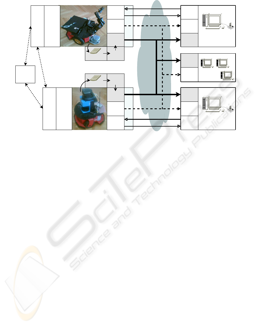
The teleoperation system considered in this paper is
schematically illustrated in Fig. 1. It consists of two
mobile robots (Scout and Manipulator) operating in
a remote environment and two operator stations with
PCs and force feedback joysticks. While the opera-
tors’ PCs (clients) are directly connected to the Inter-
net, robots’ on-board PCs (servers) are connected to
Internet via wireless LAN. Each operator controls a
single robot and receives visual and other data from
both robots.
Mobile robots that we use are PIONEER 2DX
(Scout) and PIONEER 3DX (Manipulator) manufac-
tured by ActivMedia Robotics. Scout is equipped with
an on-board PC, a ring with sixteen sonar sensors,
laser distance sensor and a Sony EVI-D30 PTZ cam-
era. Manipulator carries an external laptop computer,
a ring with sixteen sonars and a Cannon VC-C50i PTZ
camera. Additionally, a Pioneer arm with five degrees
of freedom and a gripper is mounted on the Manipu-
lator. Sonars on each robot are used for obstacle de-
tection.
Any personal computer with an adequate Inter-
net connection, a force feedback joystick and devel-
oped client application can serve as an operator sta-
tion. The client application has graphical user inter-
face (GUI) that enables the operator to preset the oper-
ation mode (driving, manipulation, observation) and
to supervise both mobile robot actions.
Logitech WingMan Force 3D Joystick used in our
experiments has two axes on which it can read inputs
and generate force: x (stick up-down) and y (stick left-
right) and two additional axes that can only read in-
puts: z (stick twist) and throttle. GUI provides ad-
ditional operator input, e.g. when switching between
operating modes. Both joystick references and GUI
input are collectively referred to as commands. When
client application is actively connected with the mo-
bile robot and driving operating mode is chosen on
the GUI, joystick x and y axes are used to input de-
sired translational and rotational velocities, respec-
tively. Force feedback is applied on the same two
axis, defying commands that would lead robot toward
detected obstacles. If manipulation operating mode is
chosen two joystick buttons are used to chose one of
arm’s 6 joints, third button sends the arm in its home
position and y axis is used to input chosen joint veloc-
ity and to display reflected force. In observation oper-
ating mode joystick x axis is used to tilt the camera, y
axis to pan it, throttle is used for adjusting zoom, and
one joystick button sends camera to its home position.
Communication between server applications run-
ning on the mobile robots’ on-board PCs and client
applications running on the operators’ PCs is initial-
ized and terminated by client applications. In spe-
cial cases, e.g. when robot is turned off or malfunc-
tioning or in case of communication failure, a server
application can refuse or terminate the connection.
Communication is implemented using three indepen-
dent communication modules: control module, im-
age transfer module and info module. Modules are
TELEOPERATION OF COLLABORATIVE MOBILE ROBOTS WITH FORCE FEEDBACK OVER INTERNET
431
Internet
n observer
stations
Dynamic
Window
Sonars
Environment
Commands
Force Feedback
operator
station 2
Image
Transfer
Module
Info
Module
Control
Module
Image
Transfer
Module
Info
Module
Control
Module
Image
Transfer
Module
Info
Module
ACTS
Framegrabber
WLAN
Dynamic
Window
Sonars
operator
station 1
Image
Transfer
Module
Info
Module
Image
Transfer
Module
Info
Module
ACTS
WLAN
Manipulator
Scout
Control
Module
Control
Module
Commands
Force Feedback
Framegrabber
Figure 1: Schematic overview of the teleoperation system.
executed within separate threads of applications and
communicate using separate communication sockets.
Modular structure decreases individual socket load
and enables each module to transfer specific type of
data without employing complicated packet schedul-
ing schemes.
Control module is used to transmit commands
from the joystick to the robot and force feedback sig-
nal from the robot to the joystick. Depending on the
operation mode, chosen on the client application GUI,
these command can be robot’s translational and angu-
lar velocities (driving mode), angular velocity of in-
dividual joints of the robot arm (manipulation mode)
or they could be commands sent to the camera: pan
and tilt angular velocity and zoom value (observation
mode). If the operator controlls mobile robot’s move-
ment or one of robot’s arm joints, control module de-
livers reflected force from the robot to the joystick. In
case the operator controlls the camera reflected force
is zero and it is only used for action synchronization.
Image transfer module transmits the frames of vi-
sual feedback signal from robots’ cameras to opera-
tors via GUI of the client application. It delivers video
signal image at a time. Cameras are connected to the
PCs via frame grabber cards and images are fetched
using ActivMedia Color Tracking System (ACTS) ap-
plication. ACTS is an application which, in combina-
tion with a color camera and frame grabber hardware
in a PC, enables custom applications to actively track
up to 320 colored objects at a full 30[fps] image ac-
quisition rate (ActivMedia, 2003). ACTS serves im-
ages to applications connected to it through TCP/IP.
This functionality was not used and communication
module was developed so that frequency and order
in which clients receive images can be directly con-
trolled. Server side communication module periodi-
cally requests an image form the ACTS and sends it
to the connected clients.
Info module transmits time noncritical informa-
tion, and is primarily used to synchronize local clocks
and transmit information about robot velocities and
arm positions to the clients.
3 FORCE FEEDBACK LOOPS
Force feedback from the remote environment gives
important information to the human operator. Two
force feedback loops have been implemented. One,
which is implemented on both mobile robots, for-
wards the force to the corresponding operator in case
of possible collision with the nearby obstacles or with
the collaborating robot. Anther one, which is imple-
mented only on Manipulator, forwards the force to its
operator’s hand when he controls the robot arm.
3.1 Event Based Action
Synchronization
Main drawback of closing a control loop over the In-
ternet is the existence of stochastic and unbounded
ICINCO 2007 - International Conference on Informatics in Control, Automation and Robotics
432
communication delay that can affect system perfor-
mance and even make it unstable. These problems
are usually addressed by ensuring passiveness of the
control loop, see e.g. (Munir, 2001), (Niemeyer,
1996) and (Niemeyer and Slotine, 2004) or by using a
non-time reference for action synchronization, as pre-
sented in (Wang and Liu, 2005), (K. Brady, 2002) and
(Luo and Su, 2003). The later approach is used here,
because there is no need for additional signal process-
ing and consequently the control system is compu-
tationally much simpler. The stability of the control
system with event-based action synchronization is en-
sured if a nondecreasing function of time is used as
the action reference (Xi and Tarn, 2000). The num-
ber of completed control cycles, which is obviously
a monotone increasing function of time, was chosen
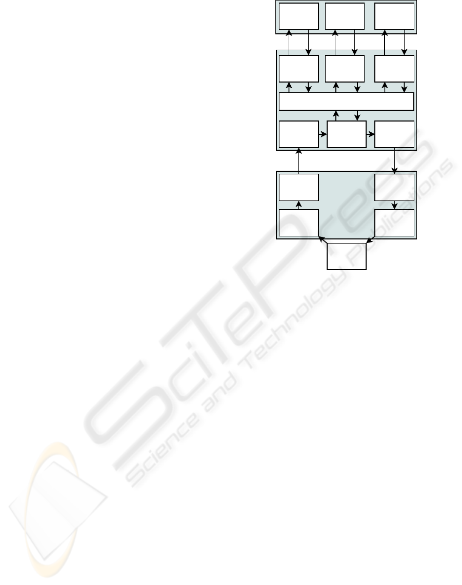
for this reference. Each control cycle (Fig. 2) is a
sequence of the following actions:
1. Server application fetches the most recent force
feedback from the buffer and sends it to the client
application.
2. Client application receives force feedback.
3. Received force is applied to the joystick.
4. New commands are read from the joystick.
5. The commands are sent to the server application.
6. Server application receives new commands and
refreshes the buffer. Depending on the operation
mode, DW algorithm or arm controller periodi-
cally fetches the command from the buffer and re-
freshes the force feedback on the buffer after its
execution. Commands are refreshed once for ev-
ery force feedback signal sent to the client appli-
cation.
Proper order of arrival of information packets is
crucial to stability of control system, even more than
their timely delivery. For this reason, UDP protocol is
used for sending operator commands and force feed-
back. UDP, unlike TCP, does not resend lost packets
and is therefore more suitable for real time applica-
tions. Additionally, UDP packets tend to be smaller
in size than corresponding TCP packets which yields
a smaller load on the communication channel. How-
ever, unreliable delivery of control packages could
break the control cycle and longer communication de-
lays may destabilize the system. To avoid this, server
application monitors control cycle duration and if it
exceeds a prescribed maximal value (e.g. 1 second),
server application initiates a new control cycle by
sending a fresh force feedback packet. All packets
that arrive outside their control cycles are simply ig-
nored.
receive
command
read
command
send
command
Client
Server
buffer
dynamic
window
send
force
receive
force
apply
force
joystick
operating mode
motion armcamera
Robot
arm
controller
camera
controller
Figure 2: Event-Based Action Synchronization between
client and server control modules.
Described event-triggered control ensures that the
force applied to the joystick corresponds to the com-
mand sent in the previous control cycle and that the
buffer state is refreshed with the command that cor-
responds to the force feedback sent in the current
control cycle. Therefore, action synchronization is
achieved using the control cycle number as a time in-
dependent reference and the system is stable.
Action synchronization between Manipulator and
its operator station is executed independently from ac-
tion synchronization between Scout and its operator
station. This arrangement is referred to as decentral-
ized event-based control (Lo et al., 2004) and it as-
sures that control cycle duration of one robot-operator
station pair is not affected by communication delays
of the other pair.
3.2 Collision Prevention
For safe robots navigation and cooperation in dy-
namic environments it is necessary to provide a
sensor-based collision prevention scheme on-board
each mobile robot. Here, we applied the DW algo-
rithm, which is a velocity space based local reactive
avoidance technique (Fox et al., 1997). Unlike di-
rectional reactive collision avoidance approaches (e.g.
potential filed, vector field histograms), the DW algo-
TELEOPERATION OF COLLABORATIVE MOBILE ROBOTS WITH FORCE FEEDBACK OVER INTERNET
433
rithm takes robot’s kinematic and dynamic constrains
directly into account by performing a search in space
of translational and rotational velocities. DW pro-
duces trajectories that consist of circular and straight
line arcs.
The DW algorithm can be integrated with a global
path planing algorithm, e.g. FD* algorithm as in
(Seder et al., 2005), for executing autonomous tasks
in partially unknown environments. While global
path planing algorithm calculates optimal path to a
specific goal, the DW algorithm takes into account
unknown and changing characteristics of the environ-
ment based on the local sensory information. We
used DW algorithm in a teleoperation system, with-
out global path planing algorithm, just to ensure safe
motion of the mobile robot and to help the operator to
better perceive obstacles. Therefore some modifica-
tions to the original algorithm had to be made.
Operator issues translational and rotational veloc-
ities’ references. DW algorithm evaluates the given
command while taking into account local sonar read-
ings and kinematic and dynamic robot constrains.
Commands that are not safe are not executed and
force feedback is generated in order to warn the oper-
ator.
Proposed DW-based collision prevention algo-
rithm consists of the following steps:
1. Desired velocities (v
d
, ω
d
) are fetched from the
buffer.
2. They are constrained by maximal and minimal
achievable velocities:
v
d
∈ [v
min
, v
max
],
ω
d
∈ [ω
min
, ω
max
]. (1)
3. Resulting velocities are additionally constrained
to values from the set of velocities V
nc
=
{v
nc
, ω
nc
} achievable in one robot control cycle.
v
d
∈ v
nc
= [v
c
− T ˙v
m
, v
c
+ T ˙v
m
],
ω
d
∈ ω
nc
= [ω
c
− T ˙ω
m
, ω
c
+ T ˙ω
m
], (2)
where v
c
and ω
c
are current velocities, ˙v
m
and ˙ω
m
are maximal accelerations/decelerations and T is
robot control cycle duration.
4. Minimal stopping path is calculated. Stopping
time and applied translational deceleration must
be established first. If condition
|
v
d
˙v
m
| > |
ω
d
˙ω
m
| (3)
is satisfied, maximal translational deceleration a
s
is applied during stopping time t
s
:
t
s
= |
v
d
˙v
m
|,
a
s
= ˙v
m
. (4)
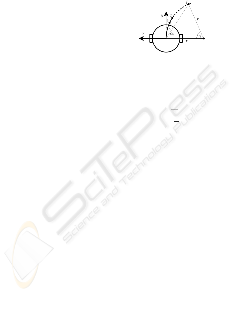
Figure 3: Trajectory of a robot is described as a circular
arc.
If (3) is not satisfied it takes more time to stop
the rotation of the robot than its translation. Then
translational deceleration smaller than maximal is
applied:
t
s
= |
ω
d
˙ω
m
|,
a
s
= |
v
d
t
s
|. (5)
Minimal stopping path s
s
is then:
s
s
= v
d
(t
s
+ t
stm
) −
a
s
t
2
s
2
, (6)
where t
stm
is additional safety time margin.
5. For the given velocities (v
d
, ω
d
) coordinates of
N
p
points on circular or straight line arc (Fig. 3)
are calculated using following equations:
γ
i
= 2α
i
= 2T N
c
i
N
p
,
x
i
= x
c
+ sgn(v
d
)rsin(γ
i
),
y
i
= y
c
+ sgn(v
d
)sgn(ω
d
)rcos(γ
i
), (7)
where (x
c
, y
c
) is the center of the arc, r =
v
d
ω
d
its radius, i = 1, . . . , N
p
is the index specifying
the point on the trajectory, from 1 to N
p
and N
c
is the number of cycles for which the algorithm is
executed.
6. Minimal allowed distance to obstacle ρ
min
is:
ρ
min
= r
r
+ s
c1
+
+(s
c2
− s
c1
)
v
d
v
max
+ s
cω
ω
ω
max
, (8)
where r
r
is robot radius, s
c1
safety clearance at
low translational velocities, s
c2
safety clearance
at high translational velocities and s
cω
rotational
safety clearance. Rotational safety clearance is set
to s
cω
= 0 because it is considered safe to rotate
the robot in place. This clearance can be set to a
higher value if rotation in place is not considered
safe, e.g. when rotating the robot with extended
ICINCO 2007 - International Conference on Informatics in Control, Automation and Robotics
434

robot arm. At low translational velocities (i.e. ve-
locities close to zero) s
c2
contributes little or not
at all to ρ
min
(ρ
min
= r
r
+s
c1
, v
d
= 0, s
cω
= 0).
At high translational velocities (i.e. velocities
close to maximum value) s
c1
has little or no in-
fluence on ρ
min
value (ρ
min
= r
r
+ s
c2
, v
d
=
v
max
, s
cω
= 0).
7. For every point on the trajectory (v
d
, ω
d
), starting
with the one closest to the robot, distance to the
closest obstacle ρ
i
(v
d
, ω
d
) is calculated and if the
condition:
ρ
i
(v
d
, ω
d
) ≥ ρ
min
(v
d
, ω
d
) (9)
is true the calculation is executed for the next
point on the trajectory. If (9) is satisfied for all
N
p
points on the trajectory then it is considered
clear, force feedback is zero and the algorithm is
finished.
8. If the condition (9) is not satisfied, path to the i-th
point on the trajectory is calculated:
s
p
= v
d
i
N
p
T N
c
(10)
9. If the path to the i-th point s
p
is smaller than stop-
ping path s
s
s
p
< s
s
, (11)
i.e. it is possible to stop the robot before it comes
closer than ρ
min
to the obstacle, trajectory is con-
sidered safe, force feedback is calculated and the
algorithm is finished. Force feedback is calculated
as follows:
F
amp
= β
p
x
2
o
+ y
2
o
,
F
ang
= atan2(y
o
, x
o
), (12)
where F
amp
and F
ang
is force feedback amplitude
(scaled to [0, 1] with scaling factor β) and direc-
tion, respectively, (x
o
, y
o
) is the closest obstacle
position in mobile robots coordinates and atan2 is
arctangent function.
10. If the condition (11) is not met, the investigated
trajectory leads to collision, i.e. leads robot closer
than ρ
min
to the obstacle. To prevent collision,
desired velocities magnitudes are decreased:
v
d(i+1)
= v
di
− v
d1
/N
s
,
ω
d(i+1)
= ω
di
− ω
d1
/N
s
, (13)
where v
d(i+1)
and ω
d(i+1)
are velocities for the
next iteration of the algorithm, v
di
and ω
di
are ve-
locities of the current iteration, v
d1
and ω
d1
are
original commanded velocities that entered the
first iteration of the algorithm and N
s
is the num-
ber of steps in which velocities are decremented.
If the new values are different than zero, algo-
rithm is repeated from step 4) until safe trajectory
is found.
3.3 Force Feedback from the
Manipulator’s Arm
During robot arm movement force is reflected when
the joint being controlled rotates to an angle that is
less than 10
◦
away from its maximum value:
F
arm
= F
max
(1 −
ξ
max
− ξ
i
10
),
|ξ
max
− ξ
i
| < 10
◦
, (14)
where F
arm
is the reflected force amplitude corre-
sponding to the current joint angle ξ
i
, F
max
maximal
reflected force amplitude, and ξ
max
maximal joint an-
gle. Feedback force informs the Manipulator’s oper-
ator that the controlled joint approaches its maximal
angle.
4 EXPERIMENTS
In order to validate the developed system a number
of experiments have been carried out during which
different signals have been recorded. Results of four
illustrative experiments are given here.
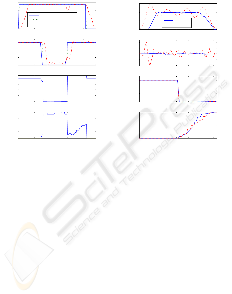
In the first experiment the operator drove the robot
around an obstacle. The commanded velocities on
client side (CS), commanded velocities on server side
(SS), measured velocities, applied force feedback di-
rection and amplitude were recorded. During the first
phase of the experiment (from 0 s to 3 s, Fig. 4)
robot moves forward and the obstacle is outside the
DW sensitivity region. Measured velocities match the
commanded ones and no force is reflected. When the
operator starts turning the robot, the obstacle enters
DW sensitivity region and force is reflected at −80
◦
informing the operator that the obstacle is on the right
from the robot (from 3 s to 6 s), and at the same time
DW limits the robot angular velocity, while transla-
tional velocity matches the commanded one. At ap-
proximately t = 6s, the operator stops turning the
robot, and the reflected force falls down, DW algo-
rithm limits for a short time first the robot transla-
tional velocity and then angular velocity. Then the
robot moves away from the obstacle and both veloc-
ities match the commanded ones, but the reflected
force again slowly increases, which is caused by the
next obstacle entering DW sensitivity region.
In the second experiment two operators, located at
different places, attempted to drive the Scout and Ma-
nipulator robots into a head-on collision. This is the
most difficult case for the modified DW algorithm to
handle as both robots see the other as a moving obsta-
cle. Velocities of both robots drop rapidly when the
TELEOPERATION OF COLLABORATIVE MOBILE ROBOTS WITH FORCE FEEDBACK OVER INTERNET
435
0 2 4 6 8
0
50
100
150
200
v [m/s]
0 2 4 6 8
−30
−20
−10
0
ω [deg/s]
Commanded velocity (CS)
Commanded velocity (SS)
Measured velocity
0 2 4 6 8
−80
−60
−40
−20
0
force direction [deg]
0 2 4 6 8
0
0.2
0.4
0.6
force amplitude
t [s]
Figure 4: One robot experiment: driving around a corner.
distance between them approaches the DW sensitiv-
ity range (at approximately t = 3s, Fig. 5). At the
same time reflected forces sent to both operators rise.
When force feedback signals reach their maximal val-
ues velocities of both robots drop to zero. Robots
stop and the collision is avoided. Fluctuation of the
Scouts’s rotational and translational velocities is due
to difficulties that its low-level velocity control sys-
tem had while following reference values. In spite of
this modified DW algorithm successfully prevented
robots from colliding. Force feedback angle should
be 0
◦
during this experiment as the obstacle is di-
rectly in front of the robot. However, this angle varies
between 0
◦
and 10
◦
. No stochastic processing was
implemented and sonars were treated as rays whose
orientation depends on sonar’s position on the robot.
Such an error is tolerated due to the fact that the force
feedback is used only to provide the operator with a
general notion about the position and distance to the
closest obstacle.
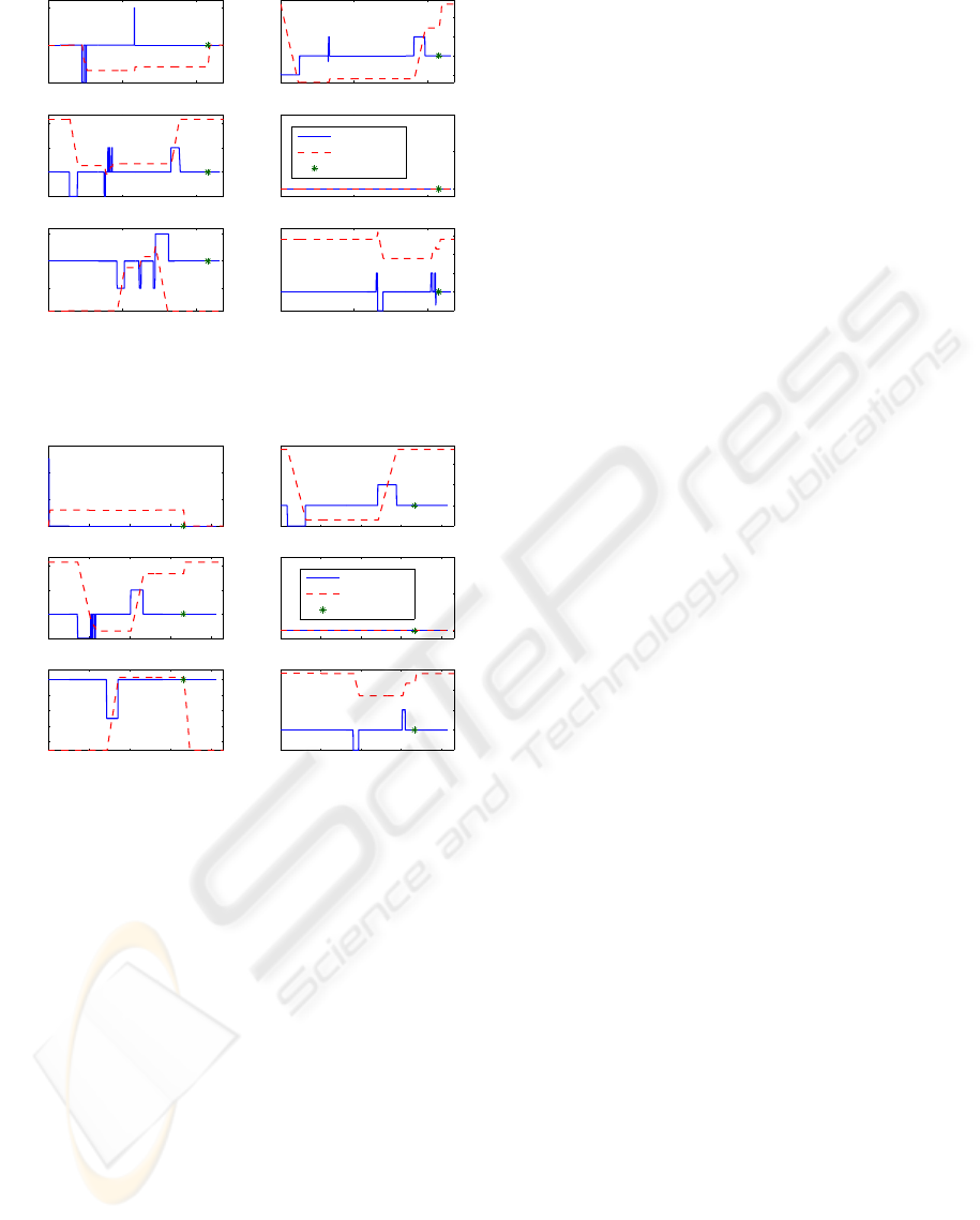
In the last two experiments the task was to pick up
a small cardboard box of the floor, place it on the Ma-
nipulator’s back and put the arm at the home position.
Only one operator controlling Manipulator accom-
plished it after few attempts and with some unneces-
0 1 2 3 4 5 6
0
100
200
300
v [m/s]
0 1 2 3 4 5 6
−10
−5
0
5
10
ω [deg/s]
0 1 2 3 4 5 6
−8
−6
−4
−2
0
2
force direction [deg]
0 1 2 3 4 5 6
0
0.5
1
force amplitude
t [s]
Manipulator
Scout
Figure 5: Velocities and force feedback recorded during two
robot collision experiment.
sary adjustments (Fig. 6). Adjustments were needed
as the camera is mounted close to the ground (for bet-
ter object grasping) not covering the entire workspace
of the arm. Another problem is the lack of infor-
mation about the third dimension which complicates
the adjustments of joint angles even when the arm
is visible to the operator. The same task can be ac-
complished much easier and faster (approximately 60
seconds in contrast to approximately 110 seconds) if
Scout and Manipulator cooperate (Fig. 7). Scout’s as-
sistance gives the Manipulator’s operator better view
of the distant site enabling him to see the arm during
the whole procedure and giving him a feel of the third
dimension.
5 CONCLUSION
A teleoperation system has been developed that en-
ables two human operators to safely control two mo-
bile robots in unknown and dynamic environments
over the Internet. Each operator receives images dis-
played on the graphical user interface, which are for-
warded by the cameras mounted on the robots, and
force feedback on the joystick, which is reflected from
ICINCO 2007 - International Conference on Informatics in Control, Automation and Robotics
436
0 50 100
−50
0
50
join 1
0 50 100
−50
0
50
100
joint 3
0 50 100
−50
0
50
joint 5
t [s]
0 50 100
−50
0
50
100
joint 2
0 50 100
0
5
10
joint 4
0 50 100
−50
0
50
100
150
gripper
t [s]
ξ [deg]
home position
˙
ξ[deg/s]
Figure 6: Motion of the robot arm joint angles during the
one experiment.
0 20 40 60 80
0
20
40
60
join 1
0 20 40 60 80
−50
0
50
100
joint 3
0 20 40 60 80
−80
−60
−40
−20
0
joint 5
t [s]
0 20 40 60 80
−50
0
50
100
joint 2
0 20 40 60 80
0
5
10
joint 4
0 20 40 60 80
−50
0
50
100
150
gripper
t [s]
ξ [deg]
home position
˙
ξ[deg/s]
Figure 7: Motion of the robot arm joint angles during the
two robots experiment.
the robot controlled by him. To overcome the in-
stability caused by the unknown and varying time
delay, event-based teleoperation system is employed
to synchronize actions of each robot with command
from its operator. Through experimental investigation
it is confirmed that developed teleoperation enables
the operator to successfully accomplish teleoperation
tasks in complex environments.
Developed teleoperation system could be easily
adjusted to different robot and sensor types to allow
application to different tasks. A possible application
could be in missions of finding and rescuing victims
from collapsed buildings in cases of natural disas-
ters, fires or terrorist attacks. For example, Scout
could be a small flying robot with various sensors that
could easily maneuver the site searching for the vic-
tims while Manipulator could be stronger robot able
to clear its way into the wreckage and carry them out
of danger zone.
REFERENCES
ActivMedia (2003). ACTS ActivMedia Robotics Color
Tracking System — User Manual. ActivMedia
Robotics LLC, Amherst.
Borenstein, J. and Koren, Y. (1990). Teleautonomous guid-
ance for mobile robots. In IEEE Transactions on Sys-
tems, Man and Cybernetics.
Fox, D., Burgard, W., and Thurm, S. (1997). The dynamic
window approach to collision avoidance. In IEEE
Robotics & Automation Magazine.
K. Brady, T. J. T. (2002). An Introduction to Online Robots.
The MIT Press, London.
Lee, D., Martinez-Palafox, O., and Spong, M. W. (2006).
Bilateral teleoperation of a wheeled mobile robot over
delayed communication network. In Proceedings of
the 2006 IEEE International Conference on Robotics
and Automation.
Lee, S., Sukhatme, G., Kim, G., and Park, C. (2002). Haptic
control of a mobile robot: A user study. In IEEE/RSJ
International Conference on Intelligent Robots and
Systems EPFL.
Lo, W., Liu, Y., Elhajj, I. H., Xi, N., Wang, Y., and
Fukada, T. (2004). Cooperative teleoperation of a
multirobot system with force reflection via internet.
In TIEEE/ASME Transactions on Mechatronics.
Luo, R. C. and Su, K. L. (2003). Networked intelligent
robots through the internet: issues and opportunities.
In IEEE Proc.
Munir, S. (2001). Internet-Based Teleoperation. PhD thesis,
Georgia Instituteof Technology, Atlanta.
Murphy, R. and Rogers, E. (1996). Cooperative assistance
for remote robot supervision. In Presence: Teleoper-
ators and Virtual Environments.
Niemeyer, G. (1996). Using Wave Variables in Time De-
layed Force Reflecting Teleoperation. PhD thesis,
MIT, Cambridge, MA.
Niemeyer, G. and Slotine, J.-J. E. (2004). Telemanipula-
tion with time delays. In The International Journal of
Robotics Research.
Seder, M., Ma
ˇ
cek, K., and Petrovi
´
c, I. (2005). An integrated
approach to real-time mobile robot control in partially
known indoor environments. In IECON.
Sheridan, T. (1992). TTelerobotics, Automation, and Hu-
man Supervisory Control. MIT Press, Cambridge,
MA.
Wang, M. and Liu, J. N. K. (2005). Interactive control for
internet-based mobile robot teleoperation. In Robotics
and Autonomous Systems.
Xi, N. and Tarn, T. J. (2000). Stability analysis of non-
time referenced internet-based telerobotic systems. In
Robotics and Autonomous Systems.
TELEOPERATION OF COLLABORATIVE MOBILE ROBOTS WITH FORCE FEEDBACK OVER INTERNET
437
