
USING SIMPLE NUMERICAL SCHEMES TO COMPUTE VISUAL
FEATURES WHENEVER UNAVAILABLE
Application to a Vision-Based Task in a Cluttered Environment
FOLIO David and CADENAT Viviane
LAAS/CNRS, 7 avenue du Colonel ROCHE,Toulouse, France
Paul SABATIER University, 118 route de Narbonne, Toulouse, France
Keywords:
Visual features estimation, visual servoing, collision avoidance.
Abstract:
In this paper, we address the problem of estimating image features whenever they become unavailable during a
vision-based task. The method consists in using numerical algorithm to compute the lacking data and allows to
treat both partial and total visual features loss. Simulation and experimental results validate our work for two
different visual-servoing navigation tasks. A comparative analysis allows to select the most efficient algorithm.
1 INTRODUCTION
Visual servoing techniques aim at controlling the
robot motion using visual features provided by a cam-
era and require that image features remain always vis-
ible (Corke, 1996; Hutchinson et al., 1996). However,
different problems may occur during the execution of
a given task: visual features loss or occlusions, cam-
era failure, and so on. In such cases, the above men-
tioned techniques cannot be used anymore and the
corresponding task will not be achieved. Thus the vi-
sual features visibility during a vision-based task ap-
pears as an interesting and challenging problem which
must be addressed. Classically, the proposed solu-
tions aim at avoiding occlusions and loss. Most of
these solutions are dedicated to manipulator arms be-
cause such robotic systems offer a sufficient number
of degrees of freedom (DOF) to benefit from redun-
dancy to treat this kind of problem (Marchand and
Hager, 1998; Mansard and Chaumette, 2005). Other
techniques preserve visibility by path-planning in the
image (Mezouar and Chaumette, 2002), by acting on
specific DOFs (Corke and Hutchinson, 2001; Malis
et al., 1999; Kyrki et al., 2004), by controlling the
zoom (Benhimane and Malis, 2003) or by making
a tradeoff with the nominal vision-based task (Re-
mazeilles et al., 2006). In a mobile robotic context,
when executing a vision-based navigation task in a
cluttered environment, it is necessary to preserve not
only the visual features visibility but also the robot
safety. A first answer to this double problem has been
proposed in (Folio and Cadenat, 2005a; Folio and Ca-
denat, 2005b). The developed methods allow to avoid
collisions, occlusions and target loss when executing
a vision-based task amidst obstacles. However they
are restricted to missions where it is possible to avoid
both occlusions and collisions without leading to local
minima. Therefore, a true extension of these works
would be to provide methods which accept that oc-
clusions may effectively occur. A first solution is to
allow some of the features to appear and disappear
temporarily from the image as done in (Garcia-Aracil
et al., 2005). However, this approach is limited to par-
tial occlusions. Another solution which is considered
in this paper is to compute the visual features as soon
as some or all of them become unavailable. Total vi-
sual features loss can then be specifically treated.
The paper is organized as follows. In section 2,
we propose a method allowing to compute the visual
features when they become unavailable. Section 3 de-
scribes the application context, and shows some sim-
ulation and experimental results validating our work.
2 VISUAL DATA ESTIMATION
In this section, we address the visual data estimation
problem whenever they become unavailable. We first
introduce some preliminaries and state the problem
326
FOLIO D. and CADENAT V. (2007).
USING SIMPLE NUMERICAL SCHEMES TO COMPUTE VISUAL FEATURES WHENEVER UNAVAILABLE - Application to a Vision-Based Task in a
Cluttered Environment.
In Proceedings of the Fourth International Conference on Informatics in Control, Automation and Robotics, pages 326-332
DOI: 10.5220/0001628503260332
Copyright
c
SciTePress
before presenting our estimation method.
2.1 Preliminaries
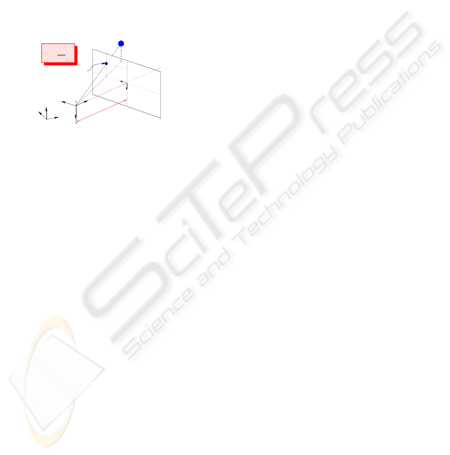
We consider a mobile camera and a vision-based task
with respect to a static landmark. We assume that
the camera motion is holonomic, characterized by
its kinematic screw:
T
c
= (V
F
c
T
C/F
0
,Ω
F
c
T
F
c
/F
0
)
T
where
V
F
c
C/F
0
= (V
X
c
,V
Y
c
,V
Z
c
)
T
and Ω
F
c
F
c
/F
0
= (Ω
X
c
,Ω
Y
c
,Ω
Z
c
)
T
represent the translational and rotational velocity of
the camera frame
F
c
with respect to the world frame
F
0
expressed in
F
c
(see figure 1).
( , , )
=
f
z
P p
Y
c
X
c
Z
c
C
F
C
X
0
Y
0
Z
0
O
0
F
x
Image plane
T
f
y
P
p
i
i i
U , V
i
i
V
U
i
i
i
( )
i
z
i
Figure 1: The pinhole camera model.
Remark 1 We do not make any hypothesis about the robot
on which is embedded the camera. Two cases may occur:
either the robot is holonomic and so is the camera motion;
or the robot is not, and we suppose that the camera is able
to move independantly from it.
Now, let s be a set of visual data provided by the
camera, and z a vector describing its depth. For a
fixed landmark, the variation of the visual signals ˙s is
related to
T
c
by means of the interaction matrix
L as
shown below (Espiau et al., 1992):
˙s =
L (s,z)T
c
(1)
This matrix allows to link the visual features motion
in the image to the 3D camera motion. It depends
mainly on the depth z (which is not always available
on line) and on the considered visual data. We sup-
pose in the sequel that we will only use image features
for which (1) can be computed analytically. Such ex-
pressions are available for different kinds of features
such as points, straight lines, circles (Espiau et al.,
1992), or image moments (Chaumette, 2004)...
2.2 Problem Statement
Now, we focus on the problem of estimating (all or
some) visual data s whenever they become unavail-
able. Different approaches, such as tracking methods
and signal processing techniques, may be used to deal
with this kind of problem. Here, we have chosen to
use a simpler approach for several reasons. First of
all, most tracking algorithms relies on measures from
the image which is unavailable in our case. Second,
as it is intended to be used to perform complex navi-
gation tasks, the estimated visual signals must be pro-
vided sufficiently rapidly with respect to the control
law sampling period. Finally, in our application, the
initial value of the visual features to be estimated is
always known, until the image become unavailable.
Thus, designing an observer or a filter is not neces-
sary, as this kind of tools is mainly interesting when
estimating the state of a dynamic system whose initial
value is unknown. Another idea is to use a 3D model
of the object together with projective geometry in or-
der to deduce the lacking data. However, this choice
would lead to depend on the considered landmark
type and would require to localize the robot. This was
unacceptable for us, as we do not want to make any
assumption on the visual feature model. Therefore,
we have chosen to solve numerically equation (1) on
the base of the visual signals previous measurements
and of the camera kinematic screw
T
c
.
As a consequence, our method will lead to closed
loop control schemes for any task where the camera
motion is defined independently from the image fea-
tures. This will be the case for example when execut-
ing a vision-based task in a cluttered environment if
the occlusion occurs in the obstacle neighborhood, as
shown in section 3. However, for “true” vision-based
tasks where
T
c
is directly deduced from the estimated
visual signals, the obtained control law remains an
open-loop scheme. Therefore, it will be restricted to
occlusions of short duration and when there is small
perturbation on the camera motion. Nonetheless, in
the context of a sole visual servoing navigation task,
this approach remains interesting as it appears as an
emergency solution when there is no other mean to
recover from a complete loss of the visual data. This
method can also be used to predict the image features
between two image acquisitions. It is then possible to
compute the control law with a higher sampling pe-
riod, and it is also quite interesting in our context.
Now, let us state our problem. As equation (1)
depends on depth z, it is necessary to evaluate this pa-
rameter together with the visual data s. Therefore, our
method requires to be able to express analytically the
variation z with respect to the camera motion. Let us
suppose that
˙
z =
L
z
T
c
. Using relation (1) and denot-
ing by X =
s
T
,z
T
T
, the differential equations to be
solved can be expressed as:
(
˙
X =
L
T
L
z
T
T
T
c
= F(X,t)
X(t
0
) = X
0
=
s
T
0
,z
T
0
T
(2)
where X
0
is the initial value of X, which can be con-
sidered known as s
0
is directly given by the feature
extraction processing and z
0
can be usually charac-
USING SIMPLE NUMERICAL SCHEMES TO COMPUTE VISUAL FEATURES WHENEVER UNAVAILABLE -
Application to a Vision-Based Task in a Cluttered Environment
327
terized off-line. Finally, for the problem to be well
stated, we assume that
T
c
has a very small variation
during each integration step h = t
k+1
−t
k
of (2).
We propose to use numerical schemes to solve the
Ordinary Differential Equations (ODE) (2). A large
overview of such methods is proposed for example in
(Shampine and Gordon, 1975). In this work, our ob-
jective is to compare several numerical schemes (Eu-
ler, Runge-Kutta, Adams-Bashforth-Moulton (ABM)
and Backward Differentiation Formulas (BDF)) to se-
lect the most efficient technique.
3 APPLICATION
We have chosen to apply the considered numerical al-
gorithms in a visual servoing context to compute the
visual features when they are lost or unavailable dur-
ing a navigation task. We have considered two kinds
of missions: the first one is a positioning vision-based
task during which a camera failure occurs; the second
one is a more complex mission consisting in realiz-
ing a visually guided navigation task amidst obstacles
despite possible occlusions and collisions.
After describing the robotic system, we present
the two missions and the obtained results.
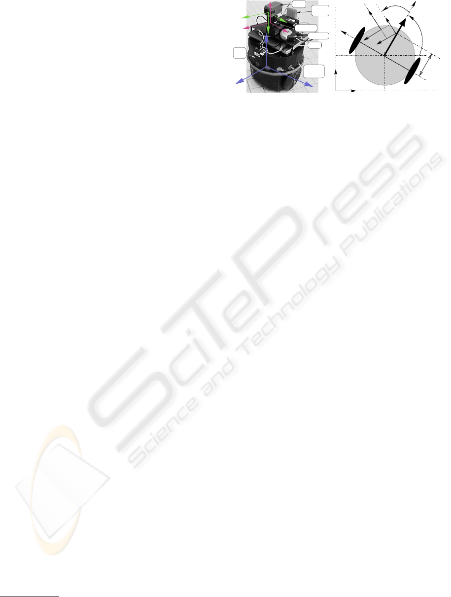
3.1 The Robotic System
We consider the mobile robot SuperScout II
1
equipped with a camera mounted on a pan-platform
(see figure 2(a)). It is a small cylindric cart-like ve-
hicle, dedicated to indoor navigation. A
DFW-VL500
Sony
color digital IEEE1394 camera captures pictures
in YUV 4:2:2 format with 640480 resolution. An im-
age processing module allows to extract points from
the image. The robot is controlled by an on-board
laptop computer running under Linux on which is in-
stalled a specific control architecture called G
en
oM
(Generator of Module) (Fleury and Herrb, 2001).
When working on the robot, three different sampling
periods are involved:
1. T
E
: the integration step defined by h = t
k+1
−t
k
,
2. T
Ctrl
≃ 44ms : the control law sampling period,
3. T
Sens
≃ 100ms : the camera sampling period.
As Linux is not a real-time OS, these values are only
approximatively known.
First, let us model our system to express the cam-
era kinematic screw. To this aim, consider figure
2(b). (x,y) are the coordinates of the robot refer-
ence point M with respect to the world frame
F
O
.
1
The mobile robot SuperScout II is provided by the AIP-
PRIMECA.
Hub firewire
link
Laptop
Ultrasonic
sensors belt
base
mobile
pan−platform
Super Scout
X
C
Ethernet
Y
P
Y
C
Z
P
Z
C
X
P
M
X
camera
Z
M
Y
M
(a) Nomadic SuperScout II.
C
y
C
z
M
y
0
x
0
y
D
x
M
θ
M
x
P
x
y
P
C
b
a
P
y
O x
ϑ
(b) Modelisation.
Figure 2: The robotic system.
θ and ϑ are respectively the direction of the vehi-
cle and the pan-platform with respect to the x
M
-axis.
P is the pan-platform center of rotation, D
x
the dis-
tance between M and P. We consider the succes-
sive frames: F
M
(M,x
M
,y
M
,z
M
) linked to the robot,
F
P
(P,x
P
,y
P
,z
P
) attached to the pan-platform, and
F
c
(C,x
c
,y
c
,z
c
) linked to the camera. The control
input is defined by the vector ˙q = (v, ω, ϖ)
T
, where v
and ω are the cart linear and angular velocities, and
ϖ is the pan-platform angular velocity with respect to
F
M
. For this specific mechanical system, the kine-
matic screw is related to the joint velocity vector by
the robot jacobian J :
T
c
= J˙q. As the camera is con-
strained to move horizontally, it is sufficient to con-
sider a reduced kinematic screw
T
r
= (V
y
c
,V
z
c
,Ω
x
c
)
T
,
and a reduced jacobian matrix J
r
as follows:
T
r
=
−sin(ϑ) D
x
cos(ϑ) + a a
cos(ϑ) D
x
sin(ϑ) − b −b
0 −1 −1
v
ω
ϖ
= J
r
˙q (3)
As det(J
r
) = D
x
6= 0, so the jacobian J
r
is always in-
vertible. Moreover, as the camera is mounted on a
pan-platform, its motion is holonomic (see remark 1).
3.2 Execution of a Vision-Based Task
Despite Camera Failure
Our objective is to perform a vision-based task de-
spite a camera failure. We first describe the consid-
ered mission and state the estimation problem for this
particular task before presenting the obtained results.
The Considered Vision-based Task. Our goal is
here to position the embedded camera with respect
to a landmark made of n points. To this aim, we have
applied the visual servoing technique given in (Espiau
et al., 1992) to mobile robots as in (Pissard-Gibollet
and Rives, 1995). In this approach which relies on the
task function formalism (Samson et al., 1991), the vi-
sual servoing task is defined as the regulation to zero
of the following error function:
e
VS
(q,t) =
C (s(q,t) − s
∗
) (4)
ICINCO 2007 - International Conference on Informatics in Control, Automation and Robotics
328
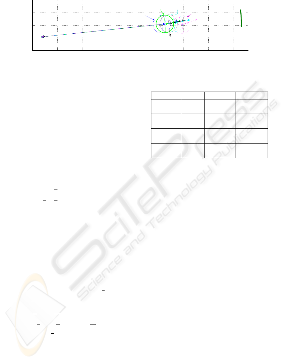
0 0.5 1 1.5 2 2.5 3 3.5 4
−0.25
0
0.25
0.5
0.75
x (m)
y (m)
Landmark
RK4
Euler
ABM
BDF
"true" final situation
(without visual feature loss)
Figure 3: Robot trajectories obtained for the different schemes.
where s is a 2n-dimensional vector made of the coor-
dinates (U
i
,V
i
) of each 3D projected point P
i
in the
image plane (see figure 1). s
∗
is the desired value
of the visual signal, while C is a full-rank combina-
tion matrix which allows to take into account more vi-
sual features than available DOF (Espiau et al., 1992).
Classically, a kinematic controller, ˙q
VS
can be deter-
mined by imposing an exponential convergence of e
VS
to zero: ˙e
VS
= C
L J
r
˙q
VS
= −λ
VS
e
VS
, where λ
VS
is a
positive scalar or a positive definite matrix. Fixing
C = L
+
as in (Espiau et al., 1992), we get:
˙q
VS
= J
−1
r
(−λ
VS
)
L
+
(s(q,t) − s
∗
) (5)
where
L is a 2n3 matrix deduced from the classical
optic flow equations (Espiau et al., 1992) as follows:
L
i
(P
i
,z
i
) =
"
0
U
z
i
U
i
V
i
f
−
f
z
i
V
i
z
i
f+
V
2
i
f
#
with i = 1..n (6)
where f is the camera focal.
Estimation Problem Statement. Let us state our
estimation problem by defining the expression of the
ODE (2) in the case of the considered task. As we
consider a target made of n points, we need first to
determine the depth variation of each of these points.
It can be easily shown that, for one 3D point p
i
of
coordinates (x
i
,y
i
,z
i
)
T
in
F
c
projected into a point
P
i
(U
i
,V
i
) in the image plane as shown in figure 1, the
depth variation ˙z
i
is related to the camera motion ac-
cording to: ˙z
i
=
L
z
i
T
r
, with L
z
i
= [0 − 1
z
i
f
V
i
]. Thus,
for the considered task, the ODE to be solved for one
point P
i
are given by:
˙
U
i
=
U
i
z
i
V
Z
c
+
U
i
V
i
f
Ω
X
c
˙
V
i
= −
f
z
i
V
Y
c
+
V
i
z
i
V
Z
c
+
f +
V
i
2
f
Ω
X
c
˙z
i
= −V
Z
c
−
z
i
f
V
i
Ω
X
c
(7)
Finally, for the considered landmark made of n points,
the ODE (2) are deduced from the above relation (7)
by defining: X = [U
1
V
1
... U
n
V
n
, z
1
... z
n
]
T
.
Experimental Results. We have experimented the
considered vision-based task on our mobile robot Su-
perScout II. For each numerical scheme, we have per-
formed the same navigation task: start from the same
Table 1: Results synthesis.
Schemes s / z std error max error
Euler s (pix) 1.0021 9.6842
z (m) 0.088256 0.72326
RK4 s (pix) 0.90919 7.0202
z (m) 0.07207 0.63849
ABM s (pix) 0.90034 5.9256
z (m) 0.05721 0.50644
BDF s (pix) 1.1172 7.6969
z (m) 0.10157 0.5989
configuration using the same s
⋆
. At the beginning of
the task, ˙q
VS
uses the visual features available from
the camera and the robot starts converging towards
the target. At the same time, the numerical algorithms
are initialized and launched. After 10 steps, the land-
mark is artificially occluded to simulate a camera fail-
ure and, if nothing is done, it is impossible to perform
the task. Controller (5) is then evaluated using the
computed values provided by each of our numerical
algorithms and the robot is controlled by an open-
loop scheme. For each considered numerical scheme
figure 3 shows the robot trajectories and table 1 sum-
marizes the whole results. These errors remain small,
which means that there are few perturbations on the
system and, in this case, our “emergency” open-loop
control scheme allows to reach a neighborhood of the
desired goal despite the camera failure. Moreover, for
the proposed task, the ABM scheme is the most effi-
cient method, as it leads to the least standard devia-
tion error (std) and to the smallest maximal error. The
RK4 algorithm gives also correct performances, while
Euler method remains the less accurate scheme as ex-
pected. As T
E
is rather small, the BDF technique pro-
vides correct results but has been proven to be much
more efficient when there are sudden variations in the
kinematic screw as it will be shown in the next part.
3.3 Realizing a Navigation Task Amidst
Possibly Occluding Obstacles
Our goal is to realize a positioning vision-based task
amidst possibly occluding obstacles. Thus, two prob-
USING SIMPLE NUMERICAL SCHEMES TO COMPUTE VISUAL FEATURES WHENEVER UNAVAILABLE -
Application to a Vision-Based Task in a Cluttered Environment
329
lems must be addressed: the visual data loss and the
risk of collision. The first one will be treated using the
above estimation technique and the second one thanks
to a rotative potential field method. We describe the
control strategy before presenting the results.
Collision and Occlusion Detection. Our control
strategy relies on the detection of the risks of collision
and occlusion. The danger of collision is evaluated
from the distance d
coll
and the relative orientation α
between the robot and the obstacle deduced from the
US sensors mounted on the robot. We define three
envelopes around each obstacle ξ
+
, ξ
0
, ξ
−
, located at
d
+
> d
0
> d
−
(see figure 4). We propose to model the
risk of collision by parameter µ
coll
which smoothly in-
creases from 0 when the robot is far from the obstacle
(d
coll
> d
0
) to 1 when it is close to it (d
coll
< d
−
).
d
coll
d
+
d
0
d
−
ξ
0
ξ
+
ξ
−
θ
α
Y
M
M
Y
Q
v
u
X
X
O
Figure 4: Obstacle avoidance.
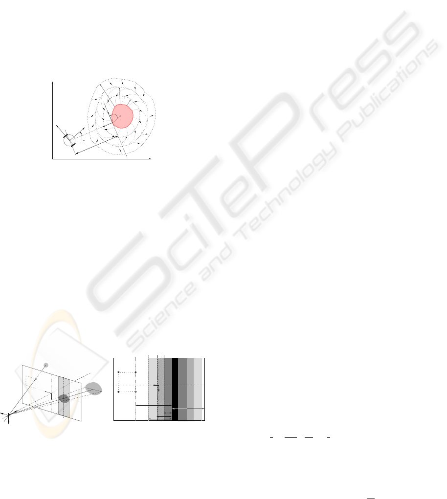
The occlusion risk is evaluated from the detection
of the occluding object left and right borders extracted
by our image processing algorithm (see figure 5(a)).
From them, we can deduce the shortest distance d
occ
between the image features and the occluding object
O , and the distance d
bord
between O and the oppo-
site image side to the visual features. Defining three
envelopes Ξ
+
, Ξ
0
, Ξ
−
around the occluding object
located at D
+
> D
0
> D
−
from it, we propose to
model the risk of occlusion by parameter µ
occ
which
smoothly increases from 0 when
O is far from the vi-
sual features (d
occ
> D
0
) to 1 when it is close to them
(d
occ
< D
−
). A possible choice for µ
coll
and µ
occ
can
be found in (Folio and Cadenat, 2005a).
Y
c
X
c
Z
c
U
P
i
p
i
T
(x,y,z)
+
V
O
−
V
O
Occluding
Object
Image Plane
C
V
i
(U , V )
i
(a) Occluding object projec-
tion in the image plane.
D
+
D
0
−
D
bord
d
occ
d
Ξ
−
Ξ
0
Ξ
+
V
MAX
V
min
V
s
P
i
Occluding object
+ −
OO
Image plane
Y
X
V V
(U , V )
ii
(b) Definition of the rele-
vant distances in the image.
Figure 5: Occlusion detection.
Global Control Law Design. Our global control
strategy relies on µ
coll
and µ
occ
. It consists in two
steps. First we define two controllers allowing re-
spectively to realize the sole vision-based task and to
guarantee non collision while dealing with occlusions
in the obstacle vicinity. Second, we switch between
these two controllers depending on the risk of occlu-
sion and collision. We propose the following global
controller:
˙q = (1− µ
coll
) ˙q
VS
+ µ
coll
˙q
coll
(8)
where ˙q
VS
is the visual servoing controller previously
defined (5), while ˙q
coll
= (v
coll
ω
coll
ϖ
coll
)
T
handles
obstacle avoidance and visual signal estimation if
necessary. Thus, when there is no risk of collision,
the robot is driven using only ˙q
VS
and executes the
vision-based task. When the vehicle enters the obsta-
cle neighborhood, µ
coll
increases to reach 1 and the
robot moves using only ˙q
coll
. This controller is de-
signed so that the vehicle avoids the obstacle while
tracking the target, treating the occlusions if any. It
is then possible to switch back to the vision-based
task once the obstacle is overcome. The avoidance
phase ends when both visual servoing and collision
avoidance controllers point out the same direction:
sign( ˙q
VS
) = sign( ˙q
coll
), and if the target is not oc-
cluded (µ
occ
= 0). In this way, we benefit from the
avoidance motion to make the occluding object leave
the image.
Remark 2 Controller (8) allows to treat occlusions which
occur during the avoidance phase. However, obstacles may
also occlude the camera field of view without inducing a
collision risk. In such cases, we may apply to the robot
either another controller allowing to avoid occlusions as
done in (Folio and Cadenat, 2005a; Folio and Cadenat,
2005b) for instance, or the open-loop scheme based on the
computed visual features given in section 3.2.
Now, it remains to design ˙q
coll
. We propose to use
a similar approach to the one used in (Cadenat et al.,
1999). The idea is to define around each obstacle a
rotative potential field so that the repulsive force is
orthogonal to the obstacle when the robot is close to it
(d
coll
< d
+
), parallel to the obstacle when the vehicle
is at a distance d
0
from it, and progressively directed
towards the obstacle between d
0
and d
+
(as shown on
figure 4). The interest of such a potential is that it
can make the robot move around the obstacle without
requiring any attractive force, reducing local minima
problems. We use the same potential function as in
(Cadenat et al., 1999):
U(d
coll
)=
1
2
k
1
(
1
d
coll
−
1
d
+
)
2
+
1
2
k
2
(d
coll
−d
+
)
2
if d
coll
≤d
+
U(d
coll
)=0 otherwise
(9)
where k
1
and k
2
are positive gains to be chosen. v
coll
and ω
coll
are then given by (Cadenat et al., 1999):
˙q
b
=
v
coll
ω
coll
T
=
k
v
F cosβ
k
ω
D
x
F sinβ
T
(10)
ICINCO 2007 - International Conference on Informatics in Control, Automation and Robotics
330
0 0.5 1 1.5 2 2.5 3 3.5
−2.5
−2
−1.5
−1
−0.5
0
0.5
1
1.5
2
2.5
x (m)
y (m)
Landmark
Initial
Situation
Final
Situation
Visual servoing only
(ie in the free space)
Repulsive Force
(F,β)
Visual servoing + Collision Avoidance
(with the BDF)
(a) Robot trajectory (using BDF)
0 5 10 15 20 25 30
0
0.2
0.4
0.6
0.8
1
µ
coll
0 5 10 15 20 25 30
0
0.2
0.4
0.6
0.8
1
µ
occ
t (s)
(b) µ
coll
and µ
occ
0 5 10 15 20 25 30 35
0
0.1
0.2
0.3
0.4
0.5
t (s)
|| s
real
− s
estim
|| at Te=0.05 (s) (pixel)
Euler
RK4
ABM
BDF
ABM: error > 10 pixels
(c) Error ks−
e
sk (pixel) for the different schemes
Figure 6: Simulation results.
where F = −
∂U
∂d
coll
is the modulus of the virtual re-
pulsive force and β = α −
π
2d
0
d
coll
+
π
2
its direction
with respect to
F
M
. k
v
and k
ω
are positive gains to
be chosen. Equation (10) drives only the mobile base
in the obstacle neighborhood. However, if the pan-
platform remains uncontrolled, it will be impossible
to switch back to the execution of the vision-based
task at the end of the avoidance phase. Therefore, we
have to address the ϖ
coll
design problem. Two cases
may occur in the obstacle vicinity: either the visual
data are available or not. In the first case, the pro-
posed approach is similar to (Cadenat et al., 1999)
and the pan-platform is controlled to compensate the
avoidance motion while centering the target in the im-
age. As the camera is constrained to move within an
horizontal plane, it is sufficient to regulate to zero the
error e
gc
= V
gc
−V
∗
gc
where V
gc
and V
⋆
gc
are the cur-
rent and desired ordinates of the target gravity center.
Rewriting equation (3) as
T
r
= J
b
˙q
b
+J
ϖ
ϖ
coll
and im-
posing an exponential decrease to regulate e
gc
to zero
(˙e
gc
=
L
V
gc
T
r
= −λ
gc
e
gc
, λ
gc
> 0), we finally obtain
(see (Cadenat et al., 1999) for more details):
ϖ
coll
=
−1
L
V
gc
J
ϖ
(λ
gc
e
gc
+
L
V
gc
J
b
˙q
b
) (11)
where
L
V
gc
is the 2
nd
row of
L
i
evaluated for V
gc
(see equation (6)). However, if the obstacle occludes
the camera field of view, s is no more available and
the pan-platform cannot be controlled anymore using
(11). At this time, we compute the visual features by
integrating the ODE (2) using one of proposed nu-
merical schemes. It is then possible to keep on ex-
ecuting the previous task e
gc
, even if the visual fea-
tures are temporary occluded by the encountered ob-
stacle. The pan-platform controller during an occlu-
sion phase will then be deduced by replacing the real
target gravity center ordinateV
gc
by the computed one
e
V
gc
in (11). We get:
e
ϖ
coll
=
−1
e
L
V
gc
J
ϖ
(λ
gc
e
e
gc
+
e
L
V
gc
J
b
˙q
b
), (12)
where
e
e
gc
=
e
V
gc
−V
∗
gc
and
e
L
V
gc
is deduced from (6).
Now, it remains to apply the suitable controller to
the pan-platform depending on the context. Recalling
that the parameter µ
occ
∈ [0;1] allows to detect occlu-
sions, we propose the following avoidance controller:
˙q
coll
=
v
coll
, ω
coll
, (1− µ
occ
)ϖ
coll
+ µ
occ
e
ϖ
coll
T
(13)
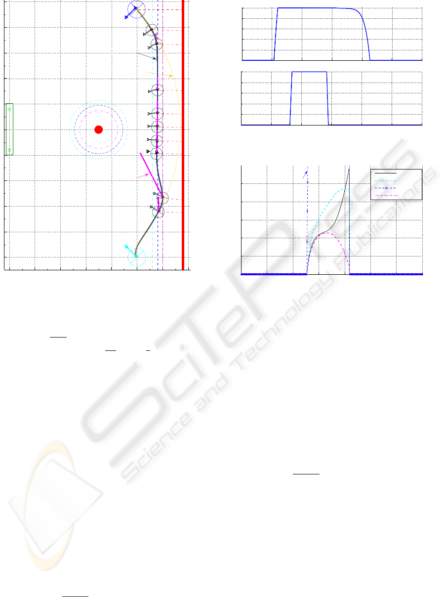
Simulation Results. The proposed method has been
simulated using Matlab software. We aim at position-
ing the camera with respect to a given landmark de-
spite two obstacles. D
−
, D
0
and D
+
have been fixed to
USING SIMPLE NUMERICAL SCHEMES TO COMPUTE VISUAL FEATURES WHENEVER UNAVAILABLE -
Application to a Vision-Based Task in a Cluttered Environment
331

40, 60 and 115 pixels, and d
−
, d
0
, d
+
to 0.3m, 0.4m,
and 0.5m. For each numerical scheme (Euler, RK4,
ABM and BDF), we have performed the same navi-
gation task, starting from the same situation and using
the same s
⋆
. Figure 6(c) shows that the BDF are the
most efficient scheme, while ABM is the worst, RK4
and Euler giving correct results for this task. Indeed,
as the obstacle avoidance induces important varia-
tions in the camera motion, ODE (2) becomes stiff,
and the BDF have been proven to be more suitable in
such cases. Figures 6(a) and 6(b) show the simulation
results obtained using this last scheme. The task is
perfectly performed despite the wall and the circular
obstacle. The different phases of the motion can be
seen on the evolution of µ
coll
and µ
occ
. At the begin-
ning of the task, there is no risk of collision, nor oc-
clusion, and the robot is driven by ˙q
VS
. When it enters
the wall neighborhood, µ
coll
increases and ˙q
coll
is ap-
plied to the robot which follows the security envelope
ξ
0
while centering the landmark. When the circular
obstacle enters the camera field of view, µ
occ
increases
and the pan-platform control smoothly switches from
ϖ
coll
to
e
ϖ
coll
. It is then possible to move along the
security envelope ξ
0
while tracking a “virtual” target
until the end of the occlusion. When there is no more
danger, the control switches back to ˙q
VS
and the robot
perfectly realizes the desired task.
4 CONCLUSIONS
In this paper, we have proposed to apply classical
numerical integration algorithms to determine visual
features whenever unavailable during a vision-based
task. The obtained algorithms have been validated
both in simulation and experimentation with interest-
ing results. A comparative analysis has been per-
formed and has shown that the BDF is particularly
efficient when ODE (2) becomes stiff while giving
correct results in more common use. Therefore, it ap-
pears to be the most interesting scheme.
REFERENCES
Benhimane, S. and Malis, E. (2003). Vision-based control
with respect to planar and non-planar objects using a
zooming camera. In Int. Conf. on Advanced Robotics,
Coimbra, Portugal.
Cadenat, V., Sou
`
eres, P., Swain, R., and Devy, M. (1999).
A controller to perform a visually guided tracking task
in a cluttered environment. In Int. Conf. on Intelligent
Robots and Systems, Korea.
Chaumette, F. (2004). Image moments: a general and useful
set of features for visual servoing. Trans. on Robotics
and Automation, 20(4):713–723.
Corke, P. (1996). Visual control of robots : High perfor-
mance visual servoing. Research Studies Press LTD.
Corke, P. and Hutchinson, S. (2001). A new partitioned
approach to image-based visual servo control. Trans.
on Robotics and Automation, 17:507–515.
Espiau, B., Chaumette, F., and Rives, P. (1992). A new
approach to visual servoing in robotics. Trans. on
Robotics and Automation.
Fleury, S. and Herrb, M. (2001). G
en
oM : User Manual.
LAAS-CNRS.
Folio, D. and Cadenat, V. (2005a). A controller to avoid
both occlusions and obstacles during a vision-based
navigation task in a cluttered environment. In Euro-
pean Control Conference(ECC-CDC’05).
Folio, D. and Cadenat, V. (2005b). Using redundancy to
avoid simultaneously occlusions and collisions while
performing a vision-based task amidst obstacles. In
European Conference on Mobile Robots, Ancona,
Italy.
Garcia-Aracil, N., Malis, E., Aracil-Santonja, R., and
Perez-Vidal, C. (2005). Continuous visual servoing
despite the changes of visibility in image features.
Trans. on Robotics and Automation, 21.
Hutchinson, S., Hager, G., and Corke, P. (1996). A tuto-
rial on visual servo control. Trans. on Robotics and
Automation.
Kyrki, V., Kragic, D., and Christensen, H. (2004). New
shortest-path approaches to visual servoing. In Int.
Conf. on Intelligent Robots and Systems.
Malis, E., Chaumette, F., and Boudet, S. (1999). 2 1/2d
visual servoing. Trans. on Robotics and Automation,
15:238–250.
Mansard, N. and Chaumette, F. (2005). A new redundancy
formalism for avoidance in visual servoing. In Int.
Conf. on Intelligent Robots and Systems, volume 2,
pages 1694–1700, Edmonton, Canada.
Marchand, E. and Hager, G. (1998). Dynamic sensor plan-
ning in visual servoing. In Int. Conf. on Robotics and
Automation, Leuven, Belgium.
Mezouar, Y. and Chaumette, F. (2002). Avoiding self-
occlusions and preserving visibility by path planning
in the image. Robotics and Autonomous Systems.
Pissard-Gibollet, R. and Rives, P. (1995). Applying vi-
sual servoing techniques to control a mobile hand-eye
system. In Int. Conf. on Robotics and Automation,
Nagoya, Japan.
Remazeilles, A., Mansard, N., and Chaumette, F. (2006).
Qualitative visual servoing: application to the visibil-
ity constraint. In Int. Conf. on Intelligent Robots and
Systems, Beijing, China.
Samson, C., Leborgne, M., and Espiau, B. (1991). Robot
Control. The Task Function Approach, volume 22 of
Oxford Engineering Series. Oxford University Press.
Shampine, L. F. and Gordon, M. K. (1975). Computer So-
lution of Ordinary Differential Equations. W. H. Free-
man, San Francisco.
ICINCO 2007 - International Conference on Informatics in Control, Automation and Robotics
332
