
A COMPONENT-BASED APPROACH FOR CONVEYING
SYSTEMS CONTROL DESIGN
Jean-Louis Lallican * **, Pascal Berruet *, André Rossi * and Jean-Luc Philippe *
* LESTER, Unniversité de Bretagne Sud, Rue de Saint Maude – BP 92116, 56321 Lorient, France
** SYDEL, Rue du Gaillec – Z.I. de Keryado – BP 2834, 56321 Lorient, France
Keywords: Conveying systems, Control engineering, Component-based approach, Generator, Model Driven
Enginnering.
Abstract: This paper deals with the design of discrete control for conveying systems. A component-based approach is
introduced to model controlled conveying systems. A component is a reusable element that includes several
views including partial models. It is formalized referring to the notion of operations. Four views are
delineated in this paper: Operating part view, Constraints view, Graphical view and Control view. Based on
such a model, a methodology allowing to automatically generate the control programs is proposed to
provide an easy way to obtain source code compatible with the IEC 61131-3 standard. Its purpose is to
automate the development of control programs in order to reduce costs. Tools allowing to implement the
methodology are also presented, along with some applications.
1 INTRODUCTION
Conveying systems are a part of manufacturing
systems that transport parcels from some locations to
new ones at a high flow. They are composed of
different types of conveyors, elevators,
consignments, sorters, and automated guided
vehicles. Conveyors can be linear, curved, and
circular. They can have pneumatic jacks, stops, and
sensors.
Designers of such manufacturing systems are
confronted to many problems. The complexity
requires modular approaches, leading to split very
large and complex design problems into simpler
ones. It is necessary to reach the best approximations
between functional solutions and material
architecture at the earliest stage of design.
Competition leads to decrease design and
implementation times. Nevertheless a conveying
system has to be robust, easy to maintain, easy to
control, flexible, modular and fault tolerant. Meeting
these requirements raises the need for a
methodology and CAD tools.
The objective of this paper is to introduce a
component-based approach for the design of discrete
control to drive conveying systems. Components
facilitate the models computation used to generate
control programs automatically. Firstly in the
context of conveying system design, the objective is
to reduce the time required to create the control.
Secondly in the context of the reconfiguration
(Berruet et al., 2005), it is necessary to provide
several versions of the control. In this case the goal
is to facilitate the creation of these controls.
The proposed methodology for generating
control programs is based on a MDE (Model Driven
Engineering) approach, in which models are
described using meta-models at each step of the
process. Transformation between these models are
expressed using a transformation language such as
ATL (Atlas Transformation Language) (Bezivin,
2005).
The present work has been developed with Sydel
society, located in Lorient (France) and specialized
in integration of conveying systems.
This paper is organized as follows. A global
design flow for conveying systems is defined in
section 2. The component approach is presented in
section 3. This paper deals only with operating part,
constraints, graphical and control views of the
components. Section 4 describes how components
are used to generate control programs and the first
experimental results are presented in section 5.
329
Lallican J., Berruet P., Rossi A. and Philippe J. (2007).
A COMPONENT-BASED APPROACH FOR CONVEYING SYSTEMS CONTROL DESIGN.
In Proceedings of the Fourth International Conference on Informatics in Control, Automation and Robotics, pages 329-336
DOI: 10.5220/0001630403290336
Copyright
c
SciTePress
2 DESIGN PROCESS
Generation of material
part model
Joint simulation of the conveying system’s material part
and its control part
Generation of control
programs
Components
library
validation
no
yes
Loading control programs
in PLC(s)
Conveying system modeling :
Component-based approach
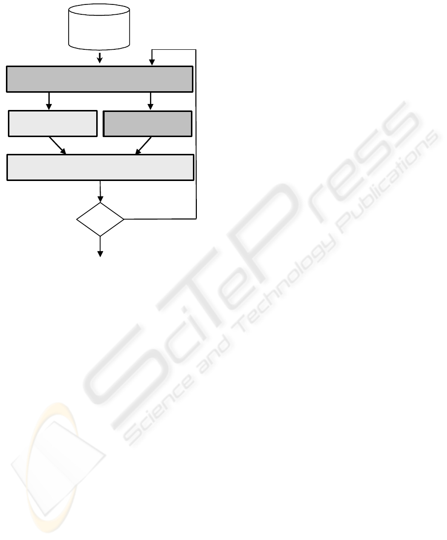
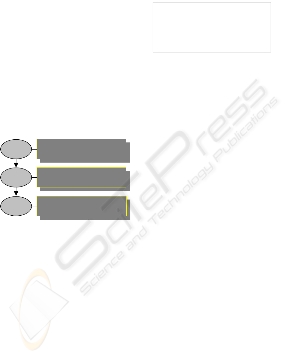
Figure 1: Global design process.
The global process is part of an usual flow based on
a simulation to validate or modify the design
parameters. It integrates a component-based
approach making it possible to facilitate design
process. Simulation concerns operating and control
parts, the control program being associated with the
operating part. A tool named SimSED (Lallican et
al., 2005) has been developed to support the
simulation. The objective of this process is to
design, to validate and to implement control of
conveying systems.
The procedure described in Figure 1 involves
four steps: system modeling, generation of material
part model, generation of control programs and
simulation. The system model is built by using a
components library. After validation, control
programs can be loaded in PLC(s) (Programmable
Logic Controller). If simulation does not correspond
to the specifications, the system model is modified.
The continuation of the paper presents the two
main steps emphasized in Figure 1. The first step
consist of building a model using a component-
based approach. It refers to operation and
component notions that are delineated in section 3.
Based on such a model, the aim of the control
programs generation step is to produce source code
that may be distributed for control.
3 COMPONENT-BASED
APPROACH
This section introduces a component-based approach
to model conveying systems. It provides a clear and
easy way to reuse previously modeled elements or to
modify the system’s internal structure. The complete
workshop model is obtained by successively
aggregating components until having one
representing the whole system. If the study is based
on an existing system, the first step consists in a
structural splitting up in order to get components
(Coudert et al., 2002).
3.1 Definitions: Operations and
Components
As components (Definition 2) refer to operations,
these last are first delineated.
Definition 1: An operation is a function
performed by a resource of the conveying system.
This concept is a specialization of the function
concept for conveying systems. In this kind of
systems, operations belong to different categories
(e.g. transfer or stocking operations). Operations are
defined for any resources whereas functions are
defined for the complete system (i.e. the conveying
system). A resource can perform several operations
and operations implement the resource
functionalities.
Based on the typology applied to generic
functions (functions of a system item defined with
no reference to the behavior of the system) and
contextual functions (adaptation or composition of
generic functions given by constituents, in response
to the requirements of the modeled system)
(Toguyeni et al., 2003), three different types of
operations are defined.
A basic operation is a generic function
performed by a basic constituent. Advance by a jack,
detection by a sensor are examples of basic
operations.
A contextual operation is a contextual function
performed by a resource. Detection of a jack
position by a sensor is a contextual operation
because the sensor is associated with the jack. A
contextual operation is issued from one or several
basic operations. Two types of contextual operations
ICINCO 2007 - International Conference on Informatics in Control, Automation and Robotics
330
have been defined (Require Position and Detect
Position).
An effective contextual operation is a
contextual function performed on a product by a
resource. Transfer from area 1 to area 2 by a jack on
a conveyor is an effective contextual operation.
Three types of effective contextual operations have
been defined: Transfer, Stocking and Detect Area.
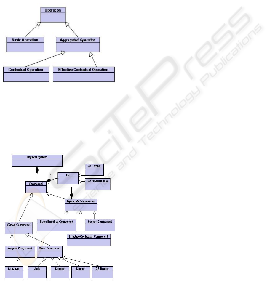
The typology of operations is represented by a
class diagram (see figure 2).
Figure 2: Typology of operations.
Definition 2: A component is a set of operations
including monitoring, supervision and control point
of views. Besides functions, it takes into account the
system structure and its physical organization.
Components types are defined by analogy to
operations types (figure 3).
Figure 3: Typology of components.
A basic component is a set of basic operations
supplied by the same constituent. Examples of basic
components available in the library, are a stopper, a
jack or a sensor. The set of basic operations can be
enriched with contextual but non effective
operations. This leads to basic enriched
component. As an example of basic component,
jack component gathers 2 basic operations: advance
and retreat by the jack. These operations are
performed by the same constituent. When sensors
(end of course) are associated, four contextual
operations are added. They are not performed by the
same constituent. The component that contains these
four operations is a basic enriched component.
The only function of a support component is to
support. A support component can support parcels. It
enables to define an area of admissible evolutions
for parts (parcels, products). This area can be
straight or curved for a conveyor. A belt conveyor is
viewed as a support component.
An effective contextual component is a set of
effective contextual operations put together,
according with the part flow. It results in general
from the association of basic components with a
support component referring to parcels. For
example, a jack component and a motor component
associated with a conveyor component enable to
define an ejector component. The ejector component
has two operations: transfer from area 1 to area 2 by
motorized conveyor, and transfer from area 1 to area
3 by the jack and the conveyor.
It has to be noticed that a support component is a
sufficient condition for defining an effective
contextual component.
A system component models the whole system
(only one system component in the model of a
conveying system exists) and refers to at least one
effective contextual component.
The component description uses a black-box
formalism. Inputs and Outputs relating to physical
flow (connected with variables corresponding to
parcels' passing) are separated from Inputs and
Outputs dedicated to control (figure 3).
Basic and support components include
parameters providing adaptability to different
designs. They are stored in a library as validated
ready-to-use models. An aggregation procedure has
been developed. It consists in building a component
of level L from several components of level L-1
brought together. Contextual components represent
the first level of aggregation. Then it is possible to
define several levels of aggregation with effective
contextual components. Finally, the system
component is the last level of aggregation (the whole
A COMPONENT-BASED APPROACH FOR CONVEYING SYSTEMS CONTROL DESIGN
331
system). As components have the same structure at
any abstraction level, the aggregated components
can easily be stored and reused for future workshops
design.
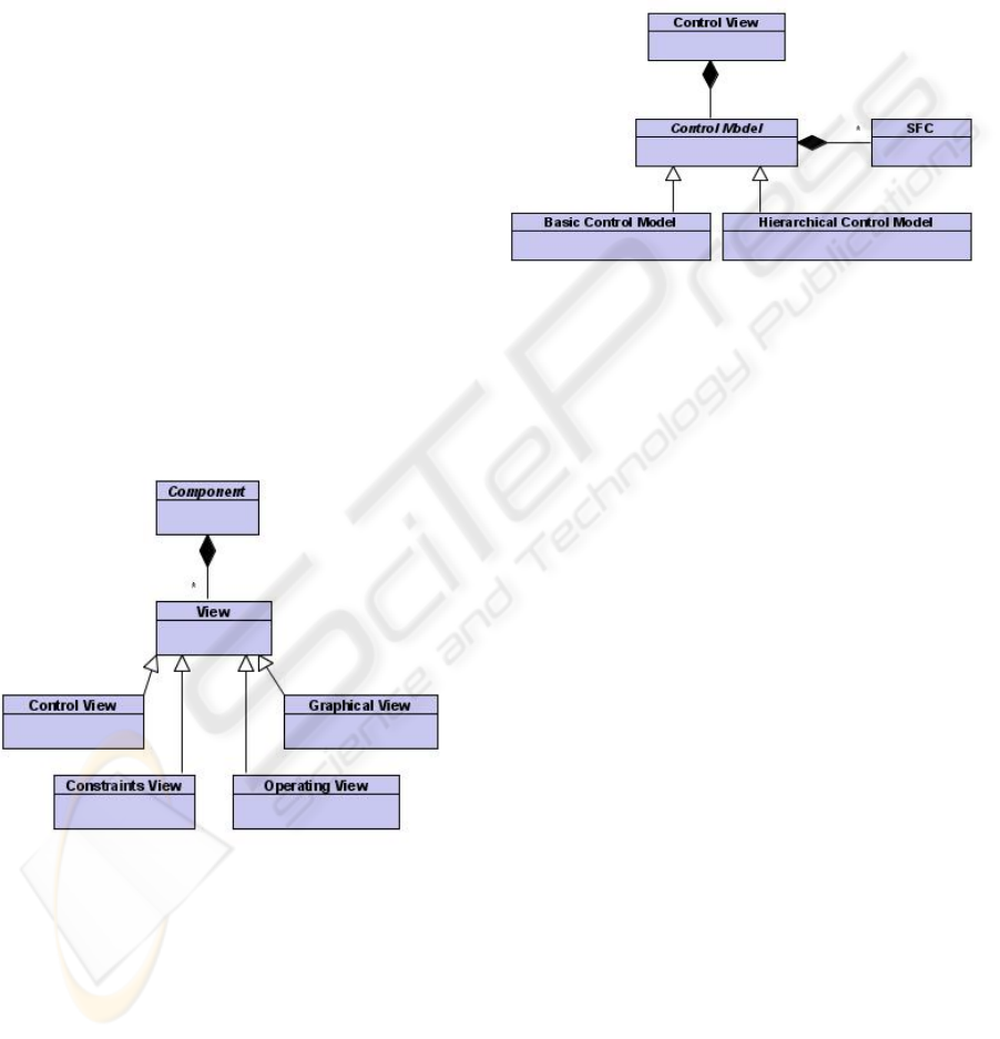
3.2 Components Views
A component is composed of four views (figure 4).
The Operating part view models the physical
behavior of the modeled entity, including both
discrete evolutions of the component and physical
laws (linear or not), in order to represent
mechanical, pneumatic and/or hydraulic phenomena.
This view is conjointly simulated with the control
part view to validate the behavior of the controlled
system (see figure 1).
The Graphical view models characteristic areas
of aggregated components. For a basic enriched
component, characteristic areas correspond to some
specific positions used for the description of
contextual operations. For example, a jack
associated with two sensors defines two positions:
beginning and end of course. For effective
contextual components, characteristic areas
correspond to areas defined by effective contextual
operations. For example, transfer operations refer to
a source zone and a destination zone.
Figure 4: A components and its views.
The Constraints view expresses the conditions
for beginning and for stopping effective contextual
operations (only transfer or stocking operations). For
example, a transfer operation can be activated when
a parcel is detected in its source area, and can be
stopped when the parcel is detected in its destination
area.
The Control view expresses the discrete control
of the modeled entity. This view is to be
implemented by controllers.
Control part is described by using of sequential
function charts (SFC) (IEC 61131-3, 2003). SFC
has the advantage of manipulating simple concepts
which are comely used by PLC program developers.
Based on the component approach, the control is a
hierarchical one (figure 5).
Figure 5: Control view.
When components of level L are selected for
aggregation, the co-ordination of the different
control parts, named hierarchical control part, has to
be generated for the level L+1 component. The
hierarchical control part, the goal of which is to
coordinate the execution of low level SFCs is also
described by means of SFCs. A high level SFC can
request a low level control part to start or to stop a
treatment. A lower level control part provides
information to a higher level SFC.
Each operation involves a SFC.
As previously described, the control structure is
a hierarchical one (figure 5). Two kinds of control
part are considered: low level control part (basic
control model) and hierarchical control part. Basic
and support components which are stored in a
library include low level control part. A hierarchical
control part refers to an aggregated component
(basic enriched component, effective contextual
component and system component).
ICINCO 2007 - International Conference on Informatics in Control, Automation and Robotics
332
4 CONTROL DESIGN
4.1 Methodology
A methodology allowing to generate automatically
the hierarchical control parts is presented in this
section. Tools used to implement this methodology
are also introduced.
Generation of hierarchical
control views
Generation and partitioning
of control programs
Partial
component model
Whole
component model
Control programs
Control system
model
Conveying system
modeling
Components
library
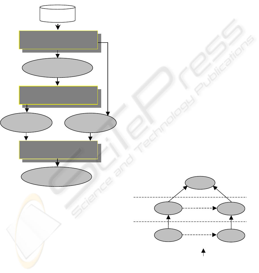
Figure 6: Control design methodology.
The control design methodology delineated in
Figure 6 involves three steps : conveying system
modeling, generation of hierarchical control views
and generation and partitioning of control programs.
These steps involve different kinds of models to
generate control programs. The first step called
conveying system modeling is dedicated to the
creation of the partial component model and the
control system model by using a components library.
These two models are detailed respectively in the
sections 4.3 and 4.4. A partial component model is
the reference from which the hierarchical control
part generation step is performed to obtain a whole
component model. This model is also detailed in the
section 4.3. Both control system model and the
whole component model are used in the step of
generation and partitioning of control programs, to
generate control programs. The control programs
generated are IEC 61131-3 compliant and are
expressed using XML (W3C). The XML files
containing the control programs are loaded in
Straton Workbench tool (Copalp, 2002) that
generates back end code.
4.2 Model Engineering
Model engineering is used to implement the three
steps emphasized in Figure 6. The model
transformation tool used is ATL (Bézivin et al.,
2003).
As seen in Figure 7, models are organized in
three layers. The bottom layer L1 is the model layer.
The previously mentioned models belong to that
layer. The meta-models are defined in the next upper
layer L2 (for example, the UML meta-model, the
“component” meta-model which has been created
for that purpose). They serve as definitions for the
models. The class diagrams represented on the
figures 2, 3, 4 and 5 compose a part of the
“component” meta-model. L3 layer is called meta-
metamodel and can be the MOF (MetaObject
Facility) (OMG, 2002) defined by the Object
Management Group (OMG). Model transformations
are defined between elements of different meta-
models and they are applied on models (conforms to
the meta-models used to define the model
transformations). Model engineering approaches
provide consistency between the different models
used in the design.
Transformations
Definition
MOF
Meta-model 1
Meta-model 2
Model 1
Model 2
Transformations
Application
Layer L3
Layer L2
Layer L1
: Conforms to
Figure 7: An overview of model transformation.
The following sub-section describes the step of
generation of hierarchical control part.
A COMPONENT-BASED APPROACH FOR CONVEYING SYSTEMS CONTROL DESIGN
333
4.3 Generation of Hierarchical Control
Part
The step called generation of hierarchical control
part is dedicated to the generation of the hierarchical
control view of each aggregated component present
in a partial component model. A partial component
model which models a conveying system, is seen as
an assembling of components. This model is known
as partial, because it does not contain the control
views of aggregated components. An algorithm is
proposed to generate automatically the control views
of aggregated components. Thus the partial
component model is refined to obtain the whole
component model. This algorithm divided into three
successive phases (figure 8) uses a library of control
templates. Each phase is dedicated to the generation
of control views of one type of aggregated
component.
Generation of control views of
basic enriched components
Generation of control views of
effective contextual components
Generation of control views of
the system component
Phase A
Phase B
Phase C
Figure 8: Phases of the generation algorithm of control
views .
The two following sub-sub-sections detail the A,
B, C phases.
4.3.1 Phases A and B
The first and second phases of the generation
algorithm of hierarchical control parts allow to
generate the control views of both basic enriched
components and effective contextual components.
This algorithm is based on a partial system model
and a library of control templates. A control
template can be compared to a SFC skeleton. In the
following paragraph, the first phase of the algorithm
is detailed precisely. The second phase is similar to
the first one, but applied to effective contextual
component.
For each contextual component in the
partial component model
For each contextual operation of
the contextual component
Select a control Template
Append the control template
Figure 9: Phase A.
The procedure described above (see figure 9) is
applied to each basic enriched component present in
the partial system model. For each contextual
operation, a control template is chosen and
supplemented. A control template is selected
according to the type of the contextual operation
(Require Position or Detect Position) and to the
position (beginning, intermediate or end position) to
which the contextual operation refers to. For
example, a contextual operation of type “require
position” which refers to a beginning or an ending
position does not use the same control template than
a contextual operation of the same type which refers
to an intermediate position. The template is then
appended according to information contained in the
model.
Four templates have been defined for the phase
A and twelve for the phase B.
4.3.2 Phase C
The third phase of the generation algorithm of
hierarchical control part is different from the
preceding ones. Indeed, the algorithm detailed in the
previous section has been enriched with a new
function called “constraint view simplifications”
(see figure 10).
Indeed, constraint views express the conditions
for beginning and for stopping effective contextual
operations. They relate to effective contextual
components and to the system component. Some
constraints can be expressed on the same effective
contextual operation by several components.
However, to generate the control view of the system
component, it is necessary to express only one
control constraint by effective contextual operation.
The function of constraints views simplification
allows to simplify the different constraints to have
only one constraint by effective contextual
operation.
ICINCO 2007 - International Conference on Informatics in Control, Automation and Robotics
334
Constraints views simplification
For each contextual component in the
partial component model
Select a control Template
Append the control template
Figure 10: Phase C.
Then, for each control constraint, a control
template is chosen and appended. Two templates
have been defined. The first template is used when a
control constraint does not define activation
conditions and the second template is used when a
control constraint defines conditions for beginning
and for stopping an effective contextual operation.
4.4 Control Programs Generation and
Partitionning
On the figure 6, the step named “generation and
partitioning of control programs” makes it possible
to generate the control programs, which are to be
implemented by PLCs, without any transcription.
This step uses a control system model which
captures all aspects of a control system in terms of
implementation (hardware components) and a whole
component model for description of control
functionalities. The approach described here follows
the Model Driven Architecture (Millar and al., 2001)
methodology, proposed by the OMG. The main
characteristic of MDA methodology is to separate
the functionalities of an application from its
development using particular technlologies. The
system functionalities are defined by the Platform
Independent Model (PIM). In our approach,
component model corresponds to the PIM. The
projection of functionalities on the hardware
architecture defines the Platform Specific Model
(PSM). Thus in our approach, the PSM corresponds
to control programs which can be implemented on
PLCs. The hardware architecture (figure 11) which
is mainly composed of PLCs, is described in the
control system model.
PLCs
External Network
Sensors /
Actuators
Figure 11: An example of hardware architecture.
5 EXPERIMENTATIONS
The methodology for the control design of
conveying system has been successfully validated on
a simple system composed of one motorized
conveyor, one jack and one sensor. The behavior of
the system is as follows: when a parcel is detected
by the sensor, the jack ejects the parcel. The system
has been modeled. From this model, the
methodology presented in the section 4, has been
applied to obtain a XML file (control programs).
The control programs are composed of 12 SFCs and
6 I/Os. They have been validated by using SimSED
tool (Lallican et al., 2006).
Jacks
Stoppers
Sensors
BC Reader
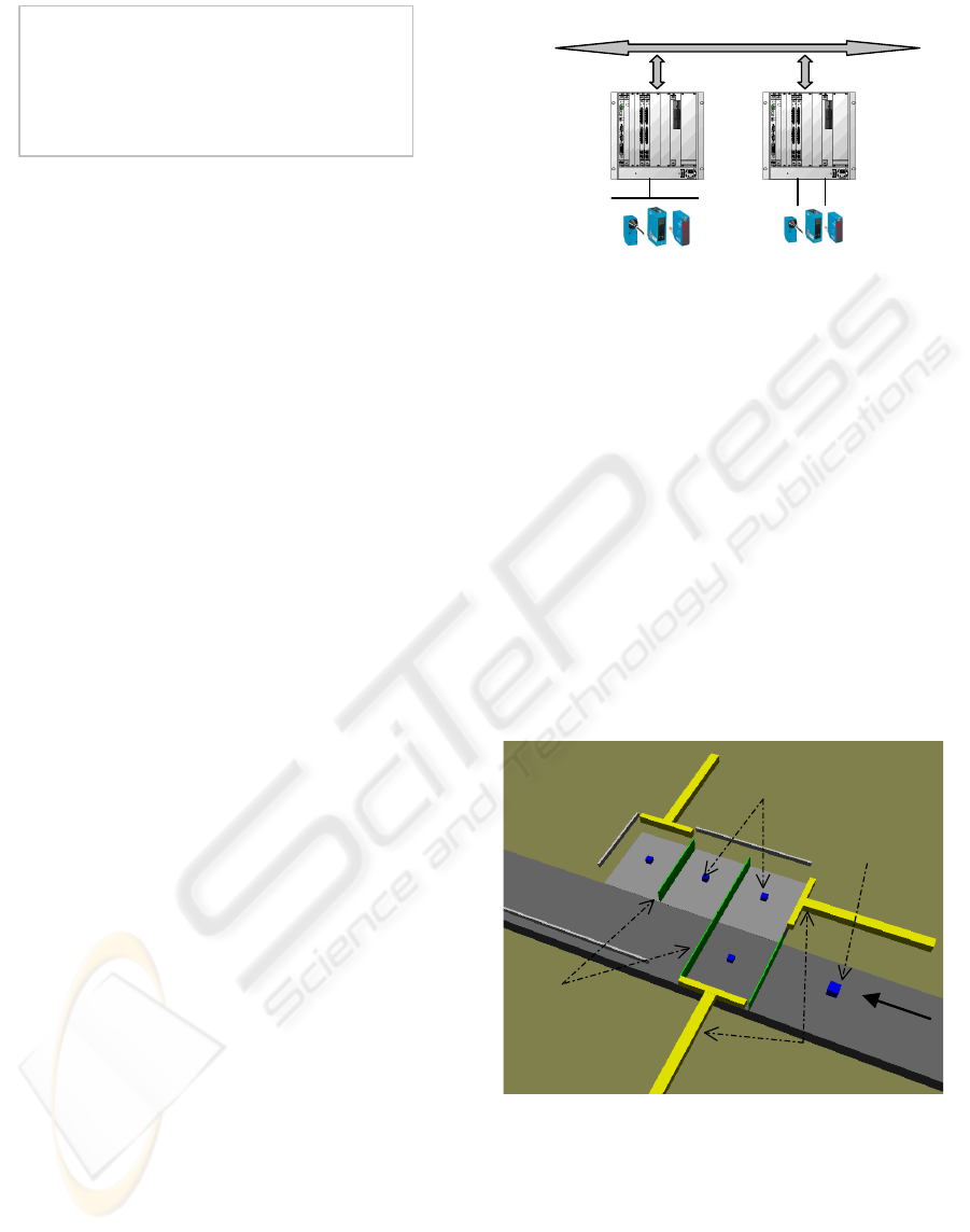
Figure 12: Example of working area.
The methodology has also been experimented on
more complex application that is based on a working
area of an industrial conveyor (figure 12).
It is composed of a bar code reader to identify
parcels, eleven sensors to detect parcels and
positions of jacks, three jacks, four stoppers and two
conveyors. The working area can accept three
product simultaneously. This system is controlled by
A COMPONENT-BASED APPROACH FOR CONVEYING SYSTEMS CONTROL DESIGN
335

a single PLC. In the model of this system we find : 2
effective contextual components, 7 basic enriched
components, 2 support components and 18 basic
components. The control programs (XML file)
generated are composed of 61 SFCs and 21 I/Os.
Some parts of the XML file are represented on the
figure 13.
<?xml version="1.0" encoding="ISO-8859-1"?>
<K5project version="1.1" path="D:\\StraProj\\testTrMStraton\\">
…..
<variables>
<varGroup name="%IX0" kind="IO">
<var name="%IX0.0=Sensor3_I_D" type="BOOL"/>
<var name="%IX0.1=Sensor23_I_D" type="BOOL"/>
<var name="%IX0.2=Sensor4_I_D" type="BOOL"/>
<programs>
<pou name="Jack3" kind="program" period="1" phase="0" lge="SFC">
<defines name="Jack3"/>
<sourceSFC>
<SFCstep kind="init" dx="1" dy="0" ref="10" name="GS10" next="GT11">
</SFCstep>
<SFCstep kind="init" dx="0" dy="0" ref="0" name="GS0" next="GT1">
</SFCstep>
<SFCstep kind=" init " dx="1" dy="2" ref="12" name="GS12" next="GT13">
<SFCaction kind="default">
<sourceSTIL>Jack3_O_R;</sourceSTIL>
</SFCaction>
Figure 13: Example of parts of the XML file.
All the behaviors have been simulated to check
the provided control. The component with its control
is stored for reusing in a project of a conveyor with
five working areas.
6 CONCLUSION
Components have been introduced, and the
advantages they offer have been pointed out as they
may be very useful to design the control of
conveying systems through the views they gather. A
methodology allowing to generate automatically
control programs (IEC 61131-3 standard compliant)
has also been described. This methodology allows
the reduction of the development costs by
improving, facilitating and systematising the
creation of the control programs. The control
programs are created at a higher level of abstraction:
engineers manipulate models instead of languages of
the IEC 61131-3 standard. The main drawback of
this methodology is that the generated programs will
be bigger than if they were built without using any
methodology.
Transformation model techniques have been
proved to be very powerful to implement code
generation. The methodology has been illustrated
through two examples.
Further works focus on the partitioning of
control programs to obtain a distributed control.
Thus, it will make possible applying the
methodology on a industrial scale system.
REFERENCES
Berruet, P., Coudert, T., Philippe, J.L, 2003, Integration of
dependability aspects in transitic systems, Proc. IEEE-
IMACS CESA 2003, Lille.
Berruet P., Lallican J-L., Rossi A., Philippe J-L., 2005, A
component based approach for the design of FMS
control and supervision, IEEE SMC , Hawaii.
Bézivin, J., Dupé, G., Jouault, F., Pitette, G., Eddine
Rougui, J., 2003, First Experiments with the ATL
Transformation Language: Transforming XSLT into
Xquery, 2ndOOPSLA Workshop on Generative
Techniques in the context of Model Driven
Architecture, Anaheim, California.
Bézivin, J., 2005, On the Unification Power of Models,
Software and SystemModeling, Springer Verlag.
Copalp, 2002, Straton Handbook.
Coudert, T., Berruet, P., Philippe, J.L., 2002, From Design
to Integration of Transitic Systems A Component
Based Approach, Proc. IECON'02, Sevilla, Vol. 1, pp.
2487-2502.
IEC 61131-3, 1993, International Electrotechnical
Commission 61131-3, Programmable controllers - Part
3: programming languages.
Lallican, J.L., Berruet, P., Philippe, J.L, 2005, SimSED: a
tool for modeling and Simulating Transitic Systems,
I3M, CMS 2005, Marseille.
Lallican, J.L., Berruet, P., Rossi, A, Philippe, J.L, 2006,
SimSED: un environnement pour modéliser et simuler
des systèmes transitiques, MOSIM, Rabat.
Millar, J., Mukerji, J., 2001, Model Driven Architecture
(MDA), OMG, ormsc/2001-07-01, Architecture Board
ORMSC1.
OMG, 2002, OMG Meta Object Facility (MOF)
Specification.
Toguyeni, A.K.A., Berruet, P., Craye, E., 2003, Models
and algorithms for failure diagnosis and recovery in
FMS, Int. J. of Flexible Manufacturing Systems, Vol
15, N°1, pp. 57-85.
W3C, Extensible Markup Language : XML,
http://www.w3.org/XML/
ICINCO 2007 - International Conference on Informatics in Control, Automation and Robotics
336
