
BEHAVIOR ACTIVITY TRACE METHOD
Application to Dead Locks Detection in a Mobile Robot Navigation
Krzysztof Skrzypczyk
Department of Automatic Control, Silesian University of Technology, Akademicka 16, 44-100 Gliwice, Poland
Keywords: Mobile robot, behavior–based robotics, data representation, navigation.
Abstract: In the paper a novel approach to representation of a history in a mobile robot navigation is presented. The
main assumptions and key definitions of the proposed approach are discussed in this paper. An application
of the method to detection a dead end situations that may occur during the work of reactive navigation
systems is presented. The potential field method is used to create an algorithm that gets the robot out of the
dead-lock. Simulations that show the effectiveness of the proposed method are also presented.
1 INTRODUCTION
An autonomous mobile robot is a machine that can
operate in an environment model of which is
unknown apriori and can react dynamical changes of
this environment (Cox and Wilfong, 1990).
Inaccurate sensors, world unpredictability and
imperfect control often cause the failure of
traditional, planner based approaches to a mobile
robot control system design (Cox and Wilfong,
1990). Therefore more efficient and faster methods
of a mobile robot collision free movement control
have been developed. One of them is a purely
reactive architecture introduced in (Braitenberg,
1984, Brooks 1991) which implements a control
strategy as a collection of stimulus-reaction pairs.
The system consists of a collection of purely
reactive rules that contain minimal internal state.
These systems use no internal models, perform no
search and merely lookup and take appropriate
action for each set of sensor readings. A Braitenberg
algorithm (Braitenberg, 1984) could be a good
example of the reactive architecture. Behavior based
control system architecture (Arkin, 1998, Brooks,
1991, Mataric , 1992, Michaud and Mataric, 1998)
embody some of the properties of reactive systems
and may contain reactive components. However the
primary feature of behavior based systems is their
distributed nature. They consist of a collection of
parallel executing behaviors devoid of centralized
reasoning module. The behaviors are more powerful
than purely reactive rules because they may use
different forms of internal representation and
perform computations on them in order to decide
what action to take. One of the key issues that
appears while designing behavior based systems is
just a representation of the knowledge about an
environment the robot is dedicated to work in
(Michaud and Mataric, 1998). Since these systems
are intended to work with the low cost, inaccurate
sensors, the problem of building a model of an
workspace is emerging. Here in this paper the
method of knowledge representation based on so
called behavior activity trace is presented. An idea
of the proposed approach is to store in a time
ordered way the knowledge of events that happened
during the robot work. What is crucial for this
method is the fact that these events are marked and
recognized by behavior characteristic sequences.
While collecting a knowledge of characteristic
events a sort of event-map is built. The advantage of
the proposed method is that this form of
representation does not consume much memory
resources. Another one is the computations using
this sort of map can be performed in an efficient
way. In the paper an example application of this
method is presented. A module of behavior based
system designed for detection of emergency
situations during the work of the system is
described. Simulation experiments proved the
proposed approach to be effective.
265
Skrzypczyk K. (2007).
BEHAVIOR ACTIVITY TRACE METHOD - Application to Dead Locks Detection in a Mobile Robot Navigation.
In Proceedings of the Fourth International Conference on Informatics in Control, Automation and Robotics, pages 265-269
DOI: 10.5220/0001633302650269
Copyright
c
SciTePress
2 THE CONTROL SYSTEM
A design of the control system used in this work is
based on the behavior-based idea of control (Arkin,
1998, Brooks, 1991). The system is composed of
behaviors that process the state and sensory
information into proper set-points for motion
controller - linear and angular velocity. The
coordination of behavior activities is made by fixed
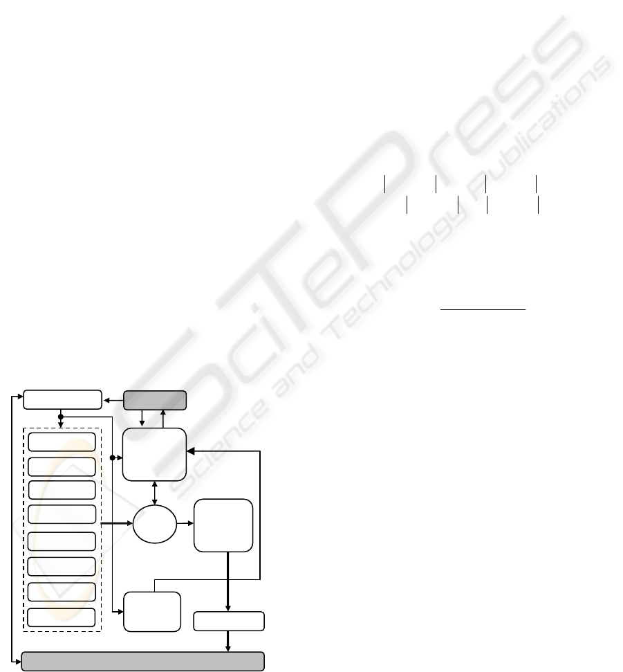
priority arbiter. A general diagram of the controller
is presented in fig.1. Its easy to distinguish five main
modules of the controller:
Behavior definition module;
Arbitration module;
Control computation module;
Task execution watcher module;
Dead lock detector module;
Each behavior can be perceived as a schema of
reaction to a given stimulus that comes from an
environment and it is represented by current sensory
information and state of the robot itself. In our
system there are eight behaviors implemented. First
four of them (avoid left, avoid right, avoid front,
speed up) are responsible for avoiding collisions
with objects located correspondingly on the left,
right, frontal and back side of the robot platform.
Fifth behavior (goal tracking) minimizes the
distance between the robot and the target. Behavior
stop simply stops the robot in case a collision is
detected or the target is reached. Sixth behavior
called stroll makes the robot goes straight in case
when no objects are detected.
Figure 1: The control system architecture.
And the last behavior – narrow passage stabilizes
robot movement preventing oscillations during
going through narrow passages. Each behavior is
designed as a function which maps a part of input
data X into activation level of the given behavior a
i
,
and it is defined by the s-class function.
Describing details of implementation of particular
behaviors is out the scope of the paper. But for
understanding concepts that are presented in the next
sections it is reasonable to show more details of an
implementation of the behavior goal tracking. This
behavior will be used further to generate action of
escape from the dead lock situation. The work of
this behavior consist in monitoring the error
Δ
Θ
between the current heading of the robot
r
ΔΘ
and
the desired heading
d
Δ
Θ
. The way of calculating
the value of the last one is presented in the section 5.
In each moment of time this behavior is checking the
error
Δ
Θ
. A value of the error is determined from:
for
2 for
dr dr
dr dr
π
π
π
⎧
Θ−Θ Θ−Θ≤
⎪
ΔΘ =
⎨
−
Θ−Θ Θ−Θ>
⎪
⎩
(1)
The heading
d
Δ
Θ
is a set point generated by the
control system. If
Δ
Θ it is greater than some
threshold value
ε
then the output signal of the
behavior is rising rapidly according to:
()
1
()
1
gt
gt
f
e
α
ε
−
ΔΘ−
ΔΘ =
+
(2)
Given behavior generates a control optimal from the
perspective of its own ”point of view”. Therefore the
method of coordination has to be used to obtain final
control of the robot optimal from the perspective of
the task executed. In our case we use the method of
priority arbitration, which select this k-th behavior
which satisfy the following:
1,2,..., 7
max( )
ii
iB
kaq
=
=
=
(3)
where q
i
denotes the priority fixed to the i-th
behavior. The activation of the selected k-th
behavior constitute the basis for computation of
robot control. Both angular and linear velocities are
defined by heuristic functions of the activation level
of the selected behavior:
[,] ( )
kk
uvfa
ω
=
=
(4)
The next module called task execution watcher, is
designed as a finite state automaton the role of
which is to supervise the process of the task
execution. The automaton is determined by four
states presented in fig.2:
Avoid L
Avoid R
Avoid F
S
p
eed U
p
Goal T
Sto
p
Narrow P
Stroll
State X
(
t
)
The task
execution
watcher
Arbiter
Dead lock
detector
The control
unit
Motors
The task
ENVIRONMENT
A
(
t
)
U
(
t
)
ICINCO 2007 - International Conference on Informatics in Control, Automation and Robotics
266

Figure 2: The finite state automaton of the task execution
watcher module.
The module starts its work in a state of waiting for a
new task to do. If the new task is sent to the module
it will switch itself to the state of execution of the
task - the robot moves in collision free way toward
the target. If task is completed the module will send
a message to the global coordinator and switch to the
first state. If any exception happens during task
execution (collision detection for instance) the robot
will stop, send appropriate message to the global
coordinator, and switch to the first state.
The aim of the above is only to sketch the main
principles and ideas of construction of the behavior
based motion controller module. Detailed
description exceeds the scope of the work and is not
its main subject. For more details please refer to
(Skrzypczyk, 2005).
3 BEHAVIOR ACTIVITY TRACE
The problem of local minima as well as dead lock
situations are the weak points of reactive systems.
Moreover, the fact that in a given moment the robot
is provided only with current information from
sensors makes the problem of detection of dead
locks hard to solve. There are many reasons of dead
end situations occurrence. One of them (and
probably the most common one) is a structure of a
workspace the robot operates inside of which.
Reactive systems are usually designed to work with
an inaccurate sensory systems. The information
provided by this kind of sensor is not sufficient for
construction of precise maps that would be useful in
environmental structure analysis. Therefore another
methods of data representation and processing
should be applied. Here in this paper we propose to
use a method of behavior activity trace. The key
issue of the proposed approach is that the system
does not store and analyze the information abut the
shape of the environment but it utilizes information
about events. Since the events are caused by a
configuration of the environmental objects
information about the structure of the workspace is
obtained in an indirect way. The discussion of the
proposed method we start with defining the notion
of the activity trace itself. While the control system
is working, in each discrete moment of time
behaviors are activated. Next in the arbitration
process the most appropriate one is selected. Since
the activity of behavior is strictly related to the
configuration of the workspace, the place the robot
was located when given behavior was activated can
be perceived as a part of a symbolic map. These
places are called further characteristic points.
Definition 1: The characteristic point CP
k
we call a
point in a cartesian space of coordinates (x
kCP
, y
kCP
)
defined by a location of the center of a mass of the
robot (x
r
, y
r
) recorded in a moment when the k-th
characteristic event occurred.
For the purpose of this work three characteristic
events were defined.
Event 1
This event is determined by a moment of beginning
of the process of navigation. The result of detection
of this event distinguishes the characteristic point
CP1.
Event 2
This event is set up when the behavior goal tracking
was selected to control the robot. It is related to the
situation when robot is far from any obstacle and
starts the tracking of the goal. The characteristic
point CP2 is related to this event.
Event 3
Third event is defined by an occurrence of a
situation when the behavior avoid front was selected
to control the robot and the condition
ε
ΔΘ < is
satisfied at the same time. Such a condition denotes
that the behavior goal tracking is slightly activated
or is not activated at all. The conditions above can
be interpreted as a detection of the obstacle on the
course of the vehicle straight toward the target.
Occurrence of such an event defines the
characteristic point CP
3
.
Now the notion of the activity trace can be
introduced.
Definition 2: The activity trace isthe time ordered
sequence of characteristic points:
The task
execution
waiting for
new task
stop the
robot
motion
send a
message
new task
an exception
the task
completed
BEHAVIOR ACTIVITY TRACE METHOD - Application to Dead Locks Detection in a Mobile Robot Navigation
267
{
}
01 1
, ,..., , 1, 2,3
nn
kk k k
TCPCP CP CP k
−
==
(5)
As can be seen the activity trace is the record of the
past activity of the robot by means of characteristic
events. The events have been recorded since a
moment of the beginning of the navigation process
t=0 till the present time
tnt
=
Δ .
4 DEAD LOCK DETECTION
The activity trace concept discussed in the previous
section was applied as a base of dead lock detection
module. On the base of multiple experiments with
the controller a few observations have been made. It
was stated that a situation when the robot is not able
to reach the target is mainly caused by a
configuration of environmental objects that form u-
shaped lay-by located on the course of the vehicle.
The undesirable behavior of the robot manifest in
repeating a sequence of actions what push the robot
into the dead end. Such a situation can be easily
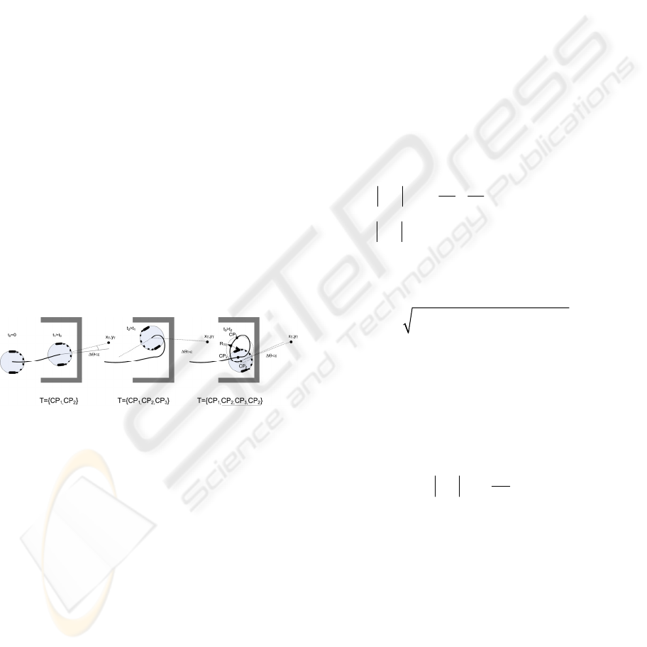
detected using behavior activity trace concept. It was
observed that dead end situation described above
corresponds to an occurrence of three element chunk
of the activity trace CP
2, CP3, CP2. The illustration
of this fact is presented in fig.3.
Figure 3: Dead lock detection based on the activity trace
concept.
Detection of this three element sequence in the
activity trace may show that the system got stuck in
a dead lock. Additionally a mutual location of the
characteristic points is checked. If all of them are
inside of a circle of a radius r
T
and a center in the
gravity center of these points that means the
navigation algorithm failed. Detected dead-lock
location is recorded in a buffer and denoted by
coordinates
,,
( , ) 1,2,...,
di di d
x
yi N=
, where N
d
denotes the number of all detected dead locks. In
such a case the recovery algorithm should be turned
on. Although the method is very simple multiple
experiments proved its efficiency.
5 RECOVERY ALGORITHM
The method described in the previous section allows
to detect the dead end situation the navigation
algorithm stuck in. Next step of the control system
synthesis is to design a recovery algorithm that is
able to get the primary algorithm out of the dead
lock. In order to construct the recovery algorithm
we utilize the concept of potential field method
(Khatib, 1986). According to this concept the
workspace of the robot is filled with artificial
potential field inside of which the robot is attracted
to its target position and repulsed away from the
obstacles. The robot navigates in direction of the
resulting virtual force vector. In order to apply this
idea to get the robot out of the trap each detected
dead-lock is considered as a source of repulsive
force that has an effect on the robot. So the value of
the repulsive force that k-th dead lock acts on the
robot is determined from
2
0
0
11
for
0otherwise
rk
k
kLL
LL
⎧
⎛⎞
⎪
=− <
⎜⎟
⎪
⎨
⎝⎠
⎪
=
⎪
⎩
r,k
r,k
F
F
(6)
where L
0
is a limit distance of influence of virtual
forces. The L
k
in (6) denotes a distance between k-th
dead lock and the robot:
22
,,
()( )
kdkr dkr
Lxxyy=−+−
(7)
The repulsive force is a vector sum of forces
generated by all dead locks:
1
d
N
k=
=
∑
rr,k
FF
(8)
The value of the attractive force is determined from
the following formula:
,
2
1
ai a
T
k
L
=F
(9)
Where L
T
in (9) is a distance between the robot and
the target. Coefficients k
r
, k
a
determine share of
each force-component in the resultant force F and
they are adjusted experimentally.Finally the
resulting force that acts on the robot is determined as
a vector sum:
=
+
ra
FF F
(10)
the argument of the vector
F determines a direction
the robot is demanded to go. Therefore the value of
the
d
Δ
Θ
from (1) is calculated as:
arg( )
d
Δ
Θ= F
(11)
ICINCO 2007 - International Conference on Informatics in Control, Automation and Robotics
268
6 SIMULATION
In order to verify the presented method it was
implemented in the M.A.S.S. simulation
environment. The workspace structure as well as the
navigation target was set in the way that create dead
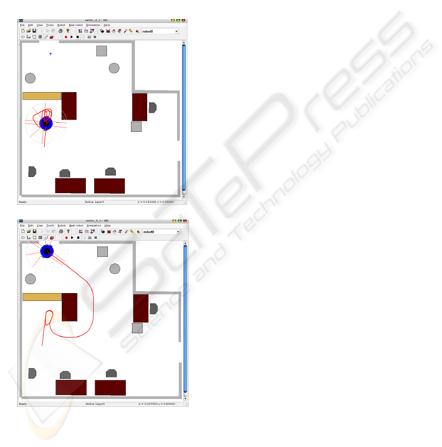
lock situations. Figure 4 present the result of the
simulation of the system without the dead lock
detector and recovery algorithm. It is easy to see that
the robot suck in the dead lock inside of an u-shaped
obstacle.
Figure 4: The result of the simulation with dead lock (a)
and the recovery algorithm action (b).
In figure 4a the situation when the robot stuck in a
dead lock is presented. In figure 4b the result of a
work of the dead lock detector and recovery
algorithm is shown. The algorithm got the robot out
of the dead lock.
7 CONCLUSION
In the paper a novel approach to representing a
history in a mobile robot navigation was presented.
The method was applied to detect a dead lock
situations that may occur during the work of reactive
navigation systems. The potential field method was
used to create an algorithm that gets the robot out of
the dead-lock. Multiple simulations proved an
efficiency of this method. There are ongoing works
focused on implementation of the method and
application to a real robot control.
ACKNOWLEDGEMENTS
This work have been supported by MNI grant no
3T11A 029 28 in the year 2007.
REFERENCES
Althaus P., Christensen H.I., 2003. Behaviour
coordination in structured environments. Advanced
Robotics, 17(7).
Arkin R. C., 1998. Behavior-Based Robotics, MIT Press,
Cambridge, MA.
Bicho E., Schoner G., 1997. The dynamic approach to
autonomous aobotics demonstrated on a low-level
vehicle platform. Robotics and Autonomous Systems,
21(1).
Braitenberg V., 1984. Vehicles: Experiments in synthetic
psychology, MIT Press.
Brooks R.A., 1991. Inteligence without representation.
Artificial Inteligence, (47).
Cox I.J., Wilfong G.T., 1990. Autonomous Robot Vehicles,
Springer-Verlag, New York.
Khatib O.:, 1986. Real-time obstacle avoidance for
manipulators and mobile robots, The International
Journal of Robotics Research 5(1).
Mataric M.J., 1992. Integration of representation into
goal-driven behavior-based robots. IEEE Transactions
on Robotics and Automation, 8(3).
Michaud M. , Mataric M. J., 1998. Learning from history
for behavior-based mobile robots in nonstationary
Conditions. Special issue on Learning in Autonomous
robots, Machine Learning, 31(1-3), and Autonomous
Robots, 5(3-4).
Skrzypczyk K., 2005. Hybrid control system of a mobile
robot. PHD dissertation, Gliwice, Poland, 2005
(a)
(b)
BEHAVIOR ACTIVITY TRACE METHOD - Application to Dead Locks Detection in a Mobile Robot Navigation
269
