
COORDINATED MOTION CONTROL OF MULTIPLE ROBOTS
Wojciech Kowalczyk and Krzysztof Kozlowski
Chair of Control and Systems Engineering, Poznan University of Technology, Piotrowo 3A, 60-965 Poznan, Poland
Keywords:
Cooperative robotics, robot formation, team work.
Abstract:
In this paper a set of robot coordination approaches is presented. Described method 0s are based on formation
function concept. Accuracy of different approaches is compared using formation function time graphs. Virtual
structure method is analyzed, then virtual structure expanded with behavioral formation feedback is presented.
Finally leader-follower scheme is described. Presented methods are illustrated by simulation results. Differ-
entially driven nonholonomic mobile robots were used in simulations.
1 INTRODUCTION
Multiple robot coordination is currently one of the
most investigated area of robotics. Great develop-
ment in computer sciences, multi-agent systems and
availability of low-cost, effective and compact digital
equipment caused that many researchers focused their
attention on this subject. Multi-agent robotic sys-
tems have wide range of applications: service robots,
transportation systems, mapping, surveillance, secu-
rity and many others.
Multi-robot coordination methods can be conven-
tionally partitioned into three classes of approaches:
virtual structure approach (Egerstedt and Hu, 2001),
(P. Ogren, 2002), (W. Kang, 2000), (Kar-Han Tan,
1997), behavioral approach (Esposito and Kumar,
2000), (J. R. Lawton and Beard, 2000), (Yamaguchi,
1998), (Yamaguchi, 1999), (Kowalczyk and Ko-
zlowski, 2005) and leader follower scheme (R. Fierro
and Ostrowski, 2001), (J. Spletzer and Kumar, 2001)
(sometimes treated as a combination of first two ap-
proaches). Each of them is more or less suitable
for particular application. There exist some solutions
with characteristic features of more than one approach
(B. J. Young and Kelsey, 2001).
In virtual structure methods control is centralized.
1
This work was supported by the Polish Ministry of Ed-
ucation and Science grant 1532/T11/2005/29.
It is suitable for the tasks that require high precision
coordinated motion of few robots, i.e. when it is
necessary to transport one huge object by the forma-
tion of robots. Centralized architecture of the control
cause that system is not scalable. Adding new agents
causes more intensive utilization of the main con-
troller. This method requires also high-speed com-
munication between main controller and agents. For
virtual structure method it is usually relatively easy to
analyze and proof stability of the system mathemati-
cally.
In behavioral method control is entirely dis-
tributed. It is not necessary to use communication;
however, using it may increase efficiency. Behavioral
methods were inspired by observations in biology and
physics. Control is decentralized and in result system
is easy scalable. Stability analysis is difficult or even
impossible. These methods are not suitable for high-
precision motion tasks, but they are very effective for
applications that can be decomposed into many inde-
pendent subtasks. In opposition to virtual structure
methods behavioral methods are fault-tolerant.
Leader-follower methods own some features from
virtual structure and behavioral methods. Communi-
cation can be used to make control more effective, but
it is not necessary. Control is distributed and in result
easy scalable, however, there is hierarchical depen-
dency between robots and as a result system is not
as fault-tolerant as in behavioral approach. Stability
155
Kowalczyk W. and Kozlowski K. (2007).
COORDINATED MOTION CONTROL OF MULTIPLE ROBOTS.
In Proceedings of the Fourth International Conference on Informatics in Control, Automation and Robotics, pages 155-160
DOI: 10.5220/0001633501550160
Copyright
c
SciTePress
roof is usually possible for leader-follower methods.
Typical applications for leader-follower methods are
spacecraft and aircraft formations. It can be also used
in mapping and exploration of the terrain.
Paper is organized as follows. In section 2 we de-
scribe feedback linearization of differentially-driven
mobile robot. In section 3 virtual structure approach
is presented. In section 4 virtual structure approach is
expanded with formation keeping behavior. In section
5 leader-follower scheme is presented. In section 6 we
conclude the paper. Simulation results are included in
sections 3-5.
2 FEEDBACK LINEARIZATION
Most of formation control methods require robots to
be fully actuated or transformed into fully actuated.
Model of such robot is given:
¨
P
i
= u
i
, (1)
where P
i
is the position vector of the i-th robot, P
i
∈
R
2
, u
i
- control force vector exerted on the i-th robot,
u
i
∈ R
2
, i = 1, 2,...,N, N - number of robots.
Two-wheel differentially-driven mobile robot can
be transformed into fully actuated using feedback lin-
earization. The same technique can be applied also
to other kind of mobile platforms. This causes that
formation control can be implemented independently
from motion controller and architecture of the robots.
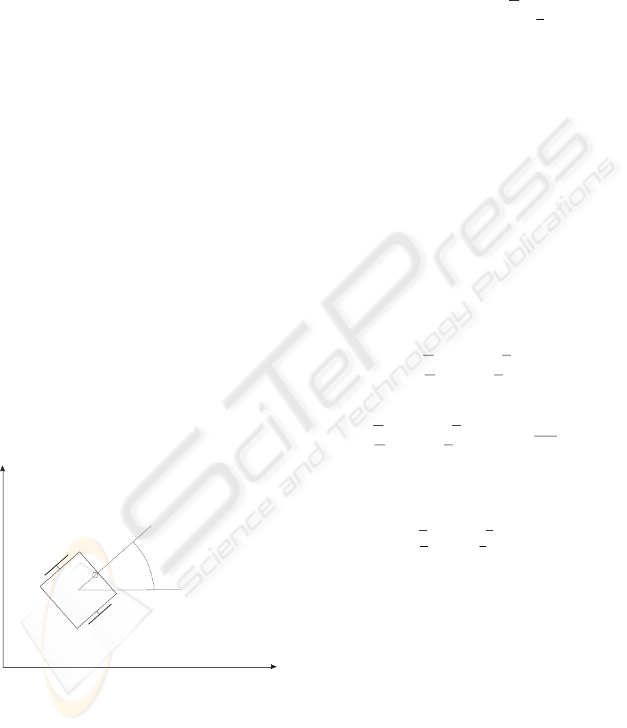
q
Y
X
L
X,Y
X ,Yc c
Figure 1: Nonholonomic differentially driven wheeled mo-
bile robot (index designating number of the robot was omit-
ted for clarity).
The motion of the i-th robot is given by:
˙x
ci
˙y
ci
˙
θ
i
˙v
i
˙
ω
i
=
v
i
· cos(θ
i
)
v
i
· sin(θ
i
)
ω
i
0
0
+
0 0
0 0
0 0
1
m
i
0
0
1
J
i
F
i
τ
i
,
(2)
where [x
ci
,y
ci
]
T
- position of the midpoint of the
wheel axis, θ
i
- orientation of the robot, v
i
- linear
velocity, ω
i
- angular velocity, m
i
- mass of the robot,
J
i
- moment of inertia of the robot, F
i
- control force
and τ
i
- control moment of force.
Dynamics of this kind of robot can be linearized if
robot’s position output is chosen suitably. As shown
in (J. R. Lawton and Beard, 2002) a good choice is
position of the point located in a distance L
i
along
the line that is perpendicular to the wheel axis and
intersects with the point [x
ci
y
ci
]
T
(Fig. 1). Selected
output can be described as follows:
x
i
y
i
=
x
ci
y
ci
+ L
i
·
cos(θ
i
)
sin(θ
i
)
(3)
Differentiating above equation twice we obtain:
¨x
i
¨y
i
=
−v
i
ω
i
sin(θ
i
) − L
i
ω
2
i
cos(θ
i
)
v
i
ω
i
cos(θ
i
) − L
i
ω
2
i
sin(θ
i
)
(4)
+
"
1
m
i
cos(θ
i
) −
L
i
J
i
sin(θ
i
)
1
m
i
sin(θ
i
)
L
i
J
i
cos(θ
i
)
#
F
i
τ
i
Since
det
"
1
m
i
cos(θ
i
) −
L
i
J
i
sin(θ
i
)
1
m
i
sin(θ
i
)
L
i
J
i
cos(θ
i
)
#
=
L
i
m
i
J
i
6= 0 (5)
the system with output [x
i
y
i
]
T
can be output feedback
linearized.
The output feedback linearizing control law is
F
i
τ
i
=
"
1
m
i
cos(θ
i
) −
L
i
J
i
sin(θ
i
)
1
m
i
sin(θ
i
)
L
i
J
i
cos(θ
i
)
#
−1
·
u
i
−
−v
i
ω
i
sin(θ
i
) − L
i
ω
2
i
cos(θ
i
)
v
i
ω
i
cos(θ
i
) − L
i
ω
2
i
sin(θ
i
)
(6)
Substituting above result into Eq. (5) and sim-
plifying we obtain feedback linearized robot model
given by Eq. (1).
3 VIRTUAL STRUCTURE
In this section virtual structure method is presented.
Concept of formation function that was introduced in
(P. Ogren, 2002) is used. Virtual structure is suitable
for applications that require very precise, coordinated
ICINCO 2007 - International Conference on Informatics in Control, Automation and Robotics
156
motion of formation of robots. As mentioned in the
introduction this approach has some disadvantages,
however, in some applications it is the only suitable
method.
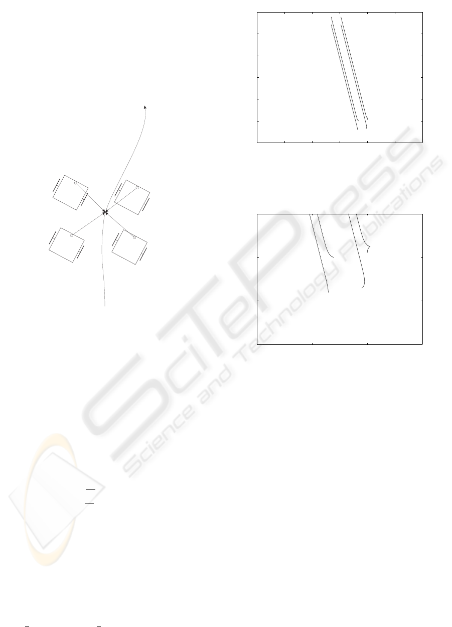
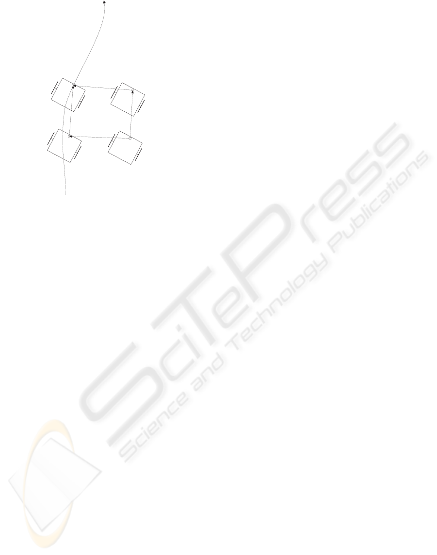
In Fig. 2 formation of four robots tracks desired
trajectory. All robots keep their relative positions P
i
,
i = 1, ...,4 to the current point of desired trajectory
P
tr j
.
P1
P4
P3
P2
Ptrj
Figure 2: Virtual structure approach - robots of the forma-
tion tracks desired trajectory with offsets given by constant
vectors (offset vectors).
The formation function is as follows:
F =
N
∑
i=1
k(P
i
− P
i of
) − P
tr j
k
2
, (7)
where P
tr j
= [x
tr j
y
tr j
]
T
is the current point on the
trajectory to be tracked by the formation, P
i of
=
[x
i of
y
i of
]
T
is the offset vector for i-th robot. Func-
tion F is positive definite, equal to zero only when all
robots of the formation match their desired positions.
Control of the i-th robot is proposed as follows:
u
i
= −K
P
"
∂F
∂x
i
∂F
∂y
i
#
− K
V
˙x
i
˙y
i
, (8)
where K
P
and K
V
are positive gains that determine
characteristics of the control. Second term in Eq. (8)
represents dumping.
In Fig. 3 trajectories of centers of masses of
four robots are shown. They follow formation tra-
jectory that starts in (0,0) position and ends in
(−1.1,4.5). Offset vectors for robots 1,...,4 are as
follows: (0.25,0.25), (−0.25,0.25), (−0.25,−0.25)
and (0.25,−0.25). Initial orientations of robots are:
θ
1
= −
π
2
, θ
2
= π, θ
3
=
π
2
and θ
4
= 0. The values
−4 −3 −2 −1 0 1 2
−1
0
1
2
3
4
5
x [m]
y [m]
Figure 3: Formation of four robots tracks desired trajectory
using virtual structure control method.
−1 −0.5 0 0.5
−1
−0.5
0
0.5
x [m]
y [m]
Figure 4: Starting segment of trajectories shown in Fig. 3.
of control gains are: K
P
= 30 and K
V
= 10. In Fig.
4 starting segments of robots trajectories are shown.
Initially all robots of the formation change their ori-
entations to θ
i
≈ 1.88rad (i = 1, ...,4) to track the de-
sired trajectory.
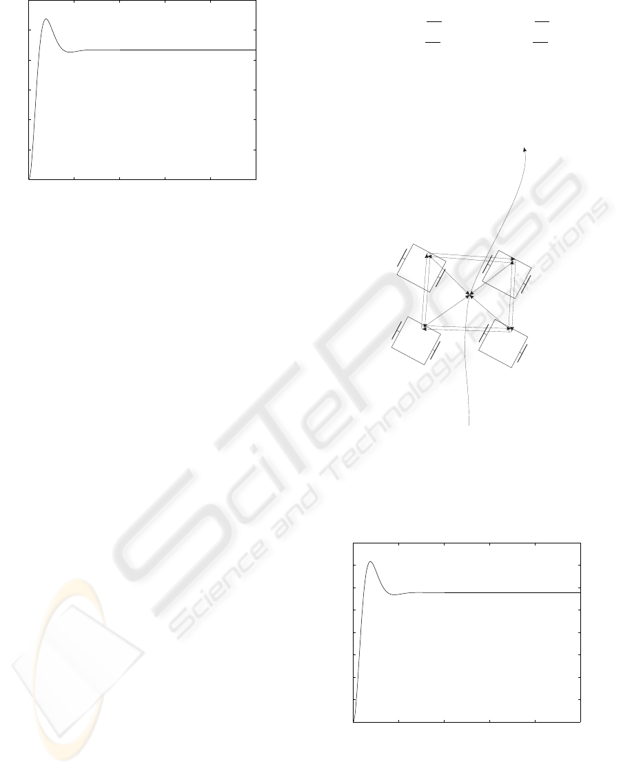
In Fig. 5 the graph of formation function as a
function of time is shown. It can be used to evaluate
the control because value of formation function repre-
sents formation error. As one can see in Fig. 5, after
transient state (about 1.5s), formation error stabilizes
below 0.9m
2
.
COORDINATED MOTION CONTROL OF MULTIPLE ROBOTS
157
0 1 2 3 4 5
0
0.02
0.04
0.06
0.08
0.1
0.12
t [s]
F [m2]
Figure 5: Formation function (time graph) for virtual struc-
ture control.
4 VIRTUAL STRUCTURE WITH
FORMATION KEEPING
BEHAVIOR
In this section we present virtual structure method ex-
panded with behavioral component. This component
provide formation feedback that cause formation to
slow down when one of robots slows down or when
it stops. In such case two concurrent goals occur:
trajectory tracking and formation keeping. Presented
method does not avoid collisions between robots. The
control algorithm try to fulfill both of them. Tuning
control gains one can set more to track the trajectory
or to keep the formation.
In Fig. 6 formation of four robots tracks desired
trajectory. All robots keep their relative positions P
i
,
to the current position of desired trajectory P
tr j
. Addi-
tionally robots keep positions relatively to their neigh-
bors.
The formation function is given as follows:
F = F
1
+ F
2
, (9)
where F
1
is given by Eq. (7) and F
2
is as follows:
F
2
=
N
∑
i=1
[ k(P
i
− P
i of
) − (P
k
− P
k of
)k
2
(10)
+ k(P
i
− P
i of
) − (P
j
− P
j of
)k
2
],
where P
k of
= [x
k of
y
k of
]
T
and P
j of
= [x
j of
y
j of
]
T
are offset vectors to k-th and j-th neighbor robot; k
and j are {4,2} for robot 1, {1,3} for robot 2, {2,4}
for robot 3 and {3,1} for robot 4. Component F
2
of
the formation function represents coupling between
robots and formation feedback.
Control of the i-th robot is given as follows:
u
i
= −K
P
"
∂F
1
∂x
i
∂F
1
∂y
i
#
− K
F
"
∂F
2
∂x
i
∂F
2
∂y
i
#
− K
V
˙x
i
˙y
i
, (11)
where K
F
is a positive factor representing the
strength of the formation feedback.
P1
P4
P3
P2
Ptrj
Figure 6: Virtual structure expanded with formation feed-
back behavior; positions of robots depend not only on the
desired formation trajectory but also on positions of other
robots of the formation.
0 1 2 3 4 5
0
0.02
0.04
0.06
0.08
0.1
0.12
0.14
0.16
t [s]
F1+F2 [m2]
Figure 7: Formation function (time graph) for virtual struc-
ture with formation keeping behavior.
In Fig. 7 graph of formation function for forma-
tion of robots that executes the same task as in section
3 is shown. The values of control gains are: K
P
= 30,
ICINCO 2007 - International Conference on Informatics in Control, Automation and Robotics
158
−4 −3 −2 −1 0 1 2
−1
0
1
2
3
4
5
x [m]
y [m]
Figure 8: Formation of four robots tracks desired trajec-
tory using virtual structure control method. Left-downrobot
fails after 1 second. Other robots slow down (in case with-
out robot failure the formation goes to position around (-1.1,
4.5), like in case shown in Fig.3).
K
F
= 30 and K
V
= 10. It is very likely that in real
application F
2
component of the formation function
will be much greater due to time delay of sensor mea-
surements and communication. Especially for large
formation of robots disturbances of the motion of one
robot will be transferred through the formation struc-
ture and affect motion of other robots. In this method
worse accuracy is the cost paid for failure immunity.
In Fig. 8 simulation results for the case when one
of robots fails is presented. Trajectory tracking and
formation keeping are performed simultaneously. The
priority of the goal depends on K
P
/K
F
ratio.
5 LEADER-FOLLOWER
In this section method based on leader-follower con-
cept is presented. In most known leader-follower
methods nonholonomic mobile robots are used.
Robot called leader tracks a desired trajectory. Other
robots keep desired separation and bearing to the
leader. Dependencies between robots in large forma-
tions may be complex: some of them are followers
and are followed by other robots at the same time.
Solution shown in this section is not typical
leader-follower scheme. As methods described in pre-
vious sections this control is based on formation func-
tion.
Leader follower approach, in its simplest form,
may be treated as a kind of virtual structure method.
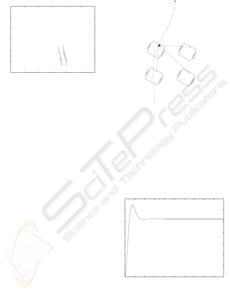
In Fig. 9 formation of four robots is shown. This con-
trol differs from virtual structure method only with
reference point for formation in fact. In the pure vir-
P1
P4
P3
P2
Ptrj
Figure 9: Leader-follower approach; one robot tracks de-
sired formation, other robots keep relative position to the
leader.
tual structure it is the point of the virtual trajectory. In
leader-follower scheme it is position of leader robot.
The formation function is given by the following
equation:
F =
N
∑
i=2
kP
i
− P
1iof
k
2
, (12)
where P
1iof
= [x
1iof
y
1iof
] is offset vector between i-
th robot leader (robot number 1).
Control of the i-th robot is given by Eq. (8).
0 0.5 1 1.5 2 2.5 3 3.5 4 4.5 5
0
0.02
0.04
0.06
0.08
0.1
0.12
0.14
t [s]
F [m2]
Figure 10: Formation function (time graph) for leader fol-
lower scheme.
In Fig. 10 the graph of formation function for four
robots that execute the same task as in section 3 is
shown.
COORDINATED MOTION CONTROL OF MULTIPLE ROBOTS
159
P1
P4
P3
P2
Figure 11: Leader-follower approach; one robot tracks de-
sired formation, two other robots keep relative position to
the leader, fourth robot keep relative position to followers.
In case shown in Fig. 11 the dependency between
robots is constructed in a different way. The leader
is followed by two robots, fourth robot keep relative
position to followers and in fact they are leaders for
this robot. Based on this concept very complex for-
mations of robots with hierarchical structure may be
built.
6 CONCLUSIONS
Three control methods for robot formation coordina-
tion were presented: virtual structure, virtual struc-
ture expanded with behavioral formation feedback
and leader-follower scheme. Their accuracies were
compared on basis of formation function graphs. Pre-
sented methods will be verified experimentally in our
future work.
REFERENCES
B. J. Young, R. W. B. and Kelsey, J. M. (2001). Coordinated
control of multiple robots using formation feedback.
Technical report, MAGICC Lab.
Egerstedt, M. and Hu, X. (2001). Formation constrained
multi-agent control. In Proceedings of the 2001 IEEE
International Conference on Robotics and Automa-
tion, pages 3961–3966, Seoul, Korea.
Esposito, J. M. and Kumar, V. (2000). A formalism for par-
allel composition of reactive and deliberative control
objectives for mobile robots. Technical report, Me-
chanical Engineering and Applied Mechanics, Univer-
sity of Pennsylvania, Philadelphia.
J. R. Lawton, B. J. Y. and Beard, R. W. (2000). A decentral-
ized approach to elementary formation maneuvers. In
Proceedings of the 2000 IEEE International Confer-
ence on Robotics and Automation, pages 2728–2733,
San Francisco, CA.
J. R. Lawton, B. Y. and Beard, R. (2002). A decentralized
approach to elementary formation manouvers.
J. Spletzer, A. K. Das, R. F. C. J. T. and Kumar, V. (2001).
Cooperative localization and control for multi-robot
manipulation. Technical report, GRASP Laboratory -
University of Pennsylvania, Philadelphia.
Kar-Han Tan, M. A. L. (1997). Virtual structures for high-
precision cooperative mobile robotic control. Techni-
cal report, Computer Science Department, University
of California, Los Angeles.
Kowalczyk, W. and Kozlowski, K. (2005). Artificial po-
tential based motion control for a large formation of
mobile robots. In ICRA ’2005, Barcelona, Spain.
P. Ogren, M. E. n. X. H. (2002). A control lyapunov func-
tion approach to multi-agent coordination. In IEEE
Transactions on Robotics and Automation, vol. 18, no.
5, pages 847–851.
R. Fierro, A. K. Das, V. K. and Ostrowski, J. P. (2001). Hy-
brid control of formation of robots. In Proceedings of
the 2001 IEEE International Conference on Robotics
and Automation, pages 3672–3677, Seoul, Korea.
W. Kang, N. Xi, A. S. (2000). Formation control of au-
tonomous agents in 3d workspace. In Proceedings of
the 2000 IEEE International Conference on Robotics
and Automation, pages 1755–1760, San Francisco,
CA.
Yamaguchi, H. (1998). A cooperative hunting behavior by
mobile robot troops. In ICRA ’98, pages 3204–3209,
Leuven, Belgium.
Yamaguchi, H. (1999). A cooperative hunting behavior by
mobile-robot troops. In The International Journal of
Robotics Research, Vol, 18, No. 8, pages 931–940.
ICINCO 2007 - International Conference on Informatics in Control, Automation and Robotics
160
