A KALMAN FILTERING APPROACH TO ESTIMATE CLAMP
FORCE IN BRAKE-BY-WIRE SYSTEMS
Stephen Saric and Alireza Bab-Hadiashar
Faculty of Engineering and Industrial Sciences, Swinburne University of Technology, John Street, Hawthorn, Australia
Keywords: Brake-by-wire, sensor fusion, dynamic stiffness, torque balance, optimisation.
Abstract: Removing a clamp force sensor from brake-by-wire (BBW) system designs has been driven by the need to
reduce costs and design complexities. In this paper an improved method is presented to estimate clamp force
using other sensory information. The proposed estimator is based on the Kalman filter where the actuator
resolver is used in a dynamic stiffness model and the actuator current sensors as well as the resolver are
used to give measurement updates in a torque balance model. Experimental results show that the estimator
can handle highly dynamic braking scenarios making it suitable for possible use in anti-lock braking system
(ABS) controls. A comparison is made with a previous attempt to estimate clamp force in BBW systems
and it is shown that the proposed estimator improves the root mean square error (RMSE) of estimation. A
training strategy is explained to ensure that the estimator can adequately adapt to parameter variations
associated with wear. This paper finally discusses reliability issues associated with the developed clamp
force estimator.
1 INTRODUCTION
Drive-by-wire (DBW) technologies are being
currently developed and introduced into the
automotive industry. One advantage of such
technologies is to produce intelligent vehicle control
systems that improve performance by benefiting
from the integration of electronic systems (Schenk et
al. 1995). The subject technology of interest in this
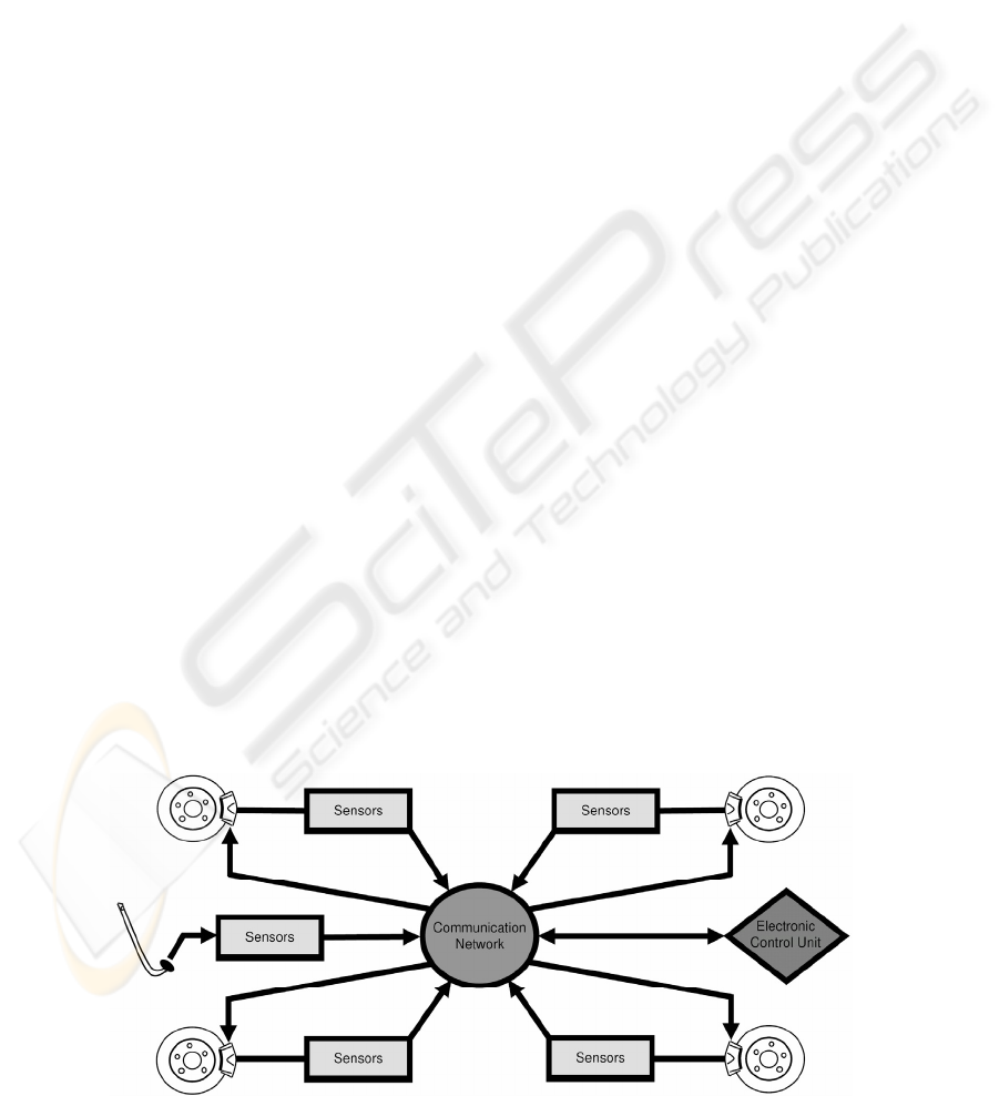
paper is BBW systems for disk brakes. Figure 1
shows a schematic diagram of a BBW system as
given by Saric et. al. (2007). A pedal feel emulator
provides the human-machine interface in a BBW
system. This pedal is fitted with sensors whose
outputs are processed by an electronic control unit
which then controls the actuators.
An electric motor that is coupled to reduction
gearing is the general setup used for an electro-
mechanical brake (EMB) actuator. The motor is
normally of a permanent magnet brushless DC type
for the reasons of compactness and enhanced
commutation efficiency. A planetary gear-set
connected to a ball-screw are generally the
components used in the reduction gearing.
Figure 1: BBW System.
249
Saric S. and Bab-Hadiashar A. (2007).
A KALMAN FILTERING APPROACH TO ESTIMATE CLAMP FORCE IN BRAKE-BY-WIRE SYSTEMS.
In Proceedings of the Fourth International Conference on Informatics in Control, Automation and Robotics, pages 249-255
DOI: 10.5220/0001643802490255
Copyright
c
SciTePress
To control EMB caliper clamping force, a clamp
force sensor is typically used to close the control
loop. A standard motion control architecture
(cascaded position, velocity and current control
loops) which is slightly altered can be used to
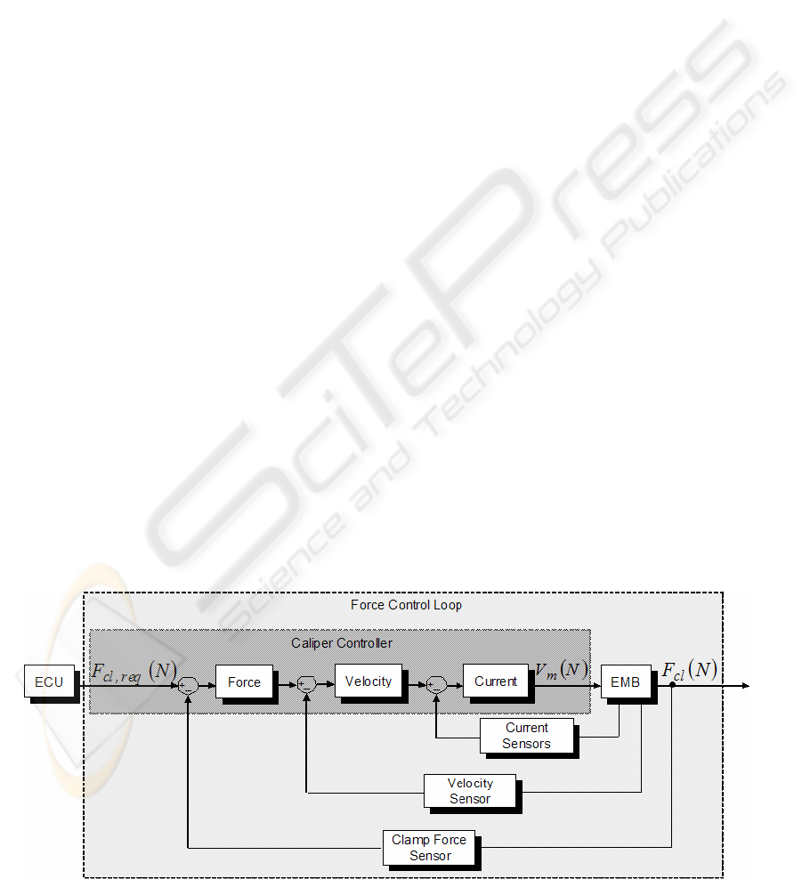
control an EMB. Line et al. (2004) exchange the
position control loop for a force control loop for
EMB control purposes. This architecture is shown in
figure 2 as given by Hoseinnezhad et. al. (2006).
The control system depicted in figure 2 requires the
use of a displacement sensor, normally a resolver,
and three motor current sensors for a three phase
brushless DC motor.
The adequate implementation of a clamp force
sensor in an EMB system can be a difficult thing to
achieve. If a clamp force sensor is placed near to a
brake pad, it must then be able to mechanically
withstand the high temperatures (up to 800
O
C) it
will be subject to. Also temperature drifts may need
to be compensated for. By embedding a clamp force
sensor deep within a caliper, i.e. at the near end of
the ball-screw this situation can be avoided.
However due to the effects of friction between the
embedded clamp force sensor location and an inner
pad, a hysteresis effect results which prevents a true
clamp force to be sensed. A clamp force sensor is a
costly item in an EMB caliper. This is due to a high
supplier cost and increased production expenses due
to its inclusion. These high production costs result
from online calibration for each individual sensor
because of performance variability from one unit to
another, as well as difficult assembly procedures due
to the small tolerances being dealt with.
The elimination of a clamp force sensor from
EMB designs is highly desirable because of the cost
issues and engineering challenges involved with its
use. A way to eliminate this component may be
realized via a sensor fusion approach, that is, to
estimate clamp force using remaining EMB system
sensors.
The introduction given here is followed by a
developmental background that briefly explains
previous works completed on estimating clamp force
in EMB systems. A description of the developmental
steps taken to attain our new clamp force estimator
is then provided, followed by describing the test rig
which we have employed. Validation results are
given which then finally leads to conclusive
remarks.
2 BBW CLAMP FORCE
ESTIMATION REVIEW
Developed torque in an EMB caliper can be
determined from motor current sensors which are
part of all EMB designs. A simplified model says
that the torque induced by a permanent magnet DC
motor is linearly related to the current passing
through the field coil, that is:
T
m
= K
m
I
m
(1)
where T
m
, I
m and
K
m
are the motor torque, the field
current and the motor torque constant respectively.
The latter term is a constant that is experimentally
determined. For a brushless permanent magnet DC
motor the current (I
m
) is the quadrature component
of the resultant current space vector as found from
the individual phases (Krishnan 2001, p. 527). Since
the motor torque input in an EMB caliper causes a
clamping force, it is apparent that a relationship
must exist between these two variables. To
determine an induced clamp force in an EMB caliper
using motor current information, a torque balance
Figure 2: EMB system control architecture.
ICINCO 2007 - International Conference on Informatics in Control, Automation and Robotics
250
can be solved as follows:
T
m
= T
a
+ T
i
+ T
f
I
m
K
m
= γ
tot
F
cl
+ J
tot
d
2
θ
m
/dt
2
+ T
f
F
cl
= (I
m
K
m
- J
tot
d
2
θ
m
/dt
2
- T
f
) / γ
tot
. (2)
The torque balance says that the torque developed
by the motor (T
m
) equals the torque required to
provide clamping force (T
a
), to meet the necessary
inertial demands (T
i
) and to overcome frictional
resistance (T
f
). By combining the load ratios from a
series connected planetary gear-set and ball-screw, it
can be found that this value (γ
tot
) acts as a gain
relating the application torque (T
a
) to the clamp
force (F
cl
). The entire caliper inertia (J
tot
) is lumped
and involves both rotational and translational
motions. This value is usually attained using
empirical data where an energy balance, over a stage
of motor acceleration, is formulated to find the
lumped inertia (J
tot
).
Equation (2) shows that the frictional torque (T
f
)
term is undefined. The reason for this is that as
Olsson et al. (1998, p. 176) explain, using theoretical
friction models for practical purposes is difficult to
achieve in a satisfactory manner. To overcome this
problem, theoretical friction models should be
merged with experimentally established phenomena
unique to a particular system. Friction models of any
sort tend to be avoided in trying to estimate clamp
force in an EMB caliper because of the problems in
trying to account for wear in the reduction gearing.
This subject will be continued in later discussion.
A clamp force estimation algorithm was
developed by Schwarz et al. (1999) for use on an
EMB caliper designed for a disk brake. Equation (2)
was involved in part within their algorithm. By
employing a differing technique they avoid the need
for using a friction model which is explained in
more detail as follows. A low amplitude high
frequency sinusoid is superimposed on the otherwise
normal angular motion from the motor. This forces
the motor to pass the same angular position in a
finite length of time between a clamping and
releasing action. At both these instants the
application of (2) yields:
T
m,cl
= γ
tot
F
cl
+ J
tot
d
2
θ
m,cl
/dt
2
+ T
f
(3)
T
m,rl
= γ
tot
F
cl
+ J
tot
d
2
θ
m,rl
/dt
2
- T
f
(4)
where the subscripts cl and rl indicate clamping and
releasing respectively. The friction terms in (3) and
(4) have approximately the same magnitudes but
opposite signs due to the change in course of motor
travel. Adding (3) and (4) cancels out the friction
terms and after some manipulation the following
equation to estimate clamp force (F
cl
*
) can be found:
F
cl
*
= (T
m,cl
+ T
m,rl
- J
tot
d
(θ
m,cl
+ θ
m,rl
) /dt
2
) /(2γ
tot
).
(5)
Passing the same motor angle via sinusoidal
differing becomes a harder and harder task to
achieve as the clamp force application rate is
increased. Also the requirement of reversing
direction in a short period of time during increased
clamp force application rates will most likely
challenge the dynamic control ability of the EMB
system. A means to cope with these problems is
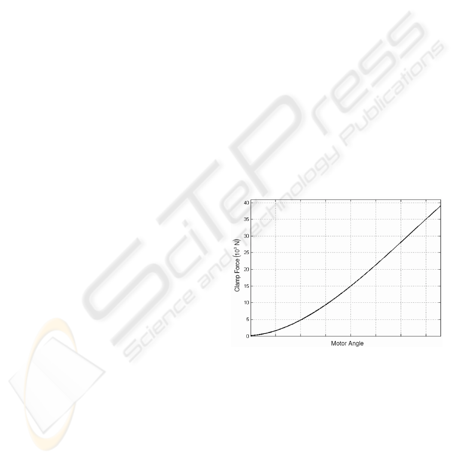
proposed by Schwarz et al. (1999). The
characteristic curve of an EMB caliper is a
relationship between motor angle and applied clamp
force where the former is varied in a pseudo-static
fashion. Figure 3 displays this curve for an EMB
caliper as given by Hoseinnezhad et. al. (2006).
Schwarz et al. (1999) put forward the use of a
caliper characteristic curve to provide feedback
control of applied clamp force. When the
opportunity to use (5) arises, it is done so with the
intentions of adapting the parameters in the
characteristic curve due to pad wear.
Figure 3: Characteristic curve for an EMB Caliper.
As provided by Hoseinnezhad et al. (2006),
figure 4 displays clamp force versus motor angle for
a highly dynamic situation where the motor angle is
varied in a uniform random fashion with a sample
time of 100 ms. It is clear that considerable dynamic
exists within the system and that the use of a
characteristic curve for clamp force estimation
purposes has its limitations for highly dynamic
scenarios. The cause of this dynamic is attributed to
viscoelastic effects exhibited mainly by the caliper
bridge. Hoseinnezhad et al. (2006) developed a
dynamic stiffness model to handle such viscoelastic
A KALMAN FILTERING APPROACH TO ESTIMATE CLAMP FORCE IN BRAKE-BY-WIRE SYSTEMS
251
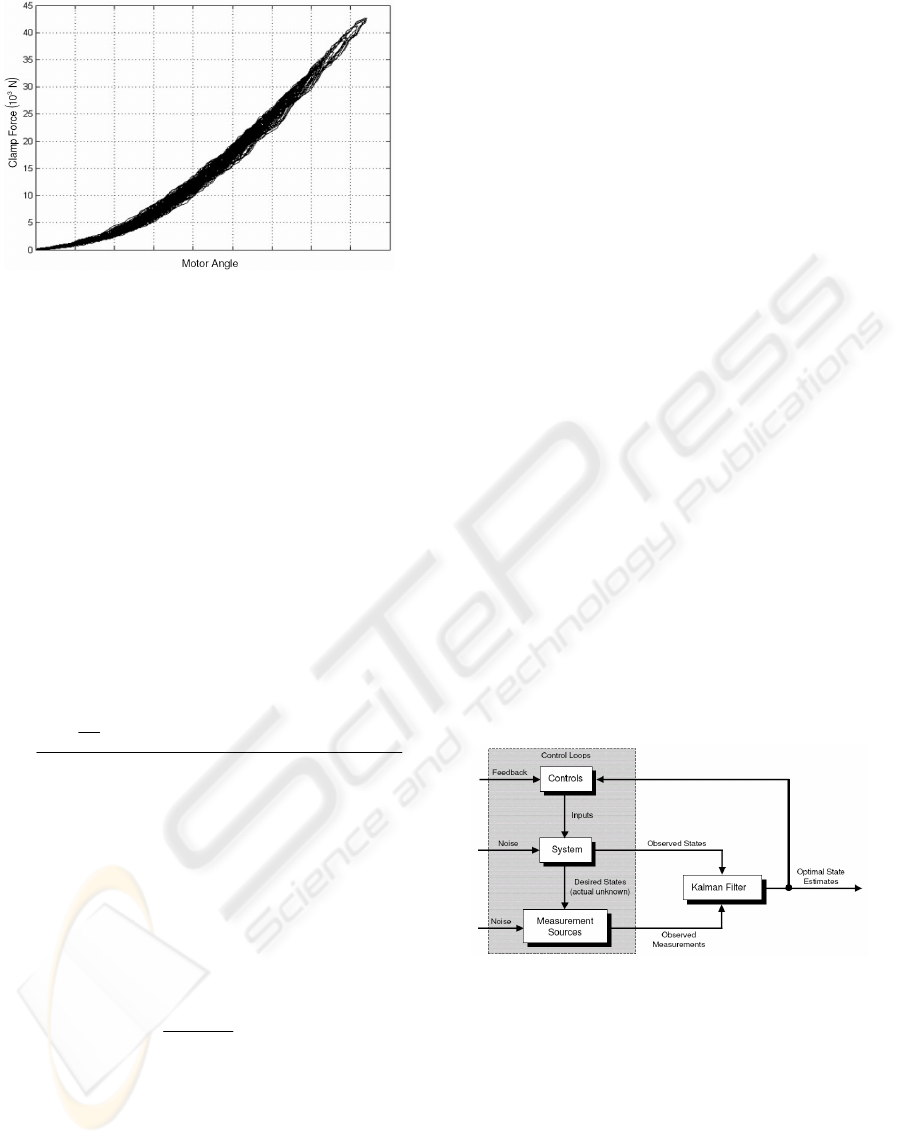
Figure 4: Clamp force versus motor angle for highly
dynamic case.
effects. This model is given as follows in discrete
time notation:
1)-(α+)(θα+)(θα+)(θα=)(
01
2
2
3
3
kFkkkkF
*
cl
mmm
*
cl
(6)
where α
4
, α
3
, α
2
, α
1
and α
0
are experimentally
determined constants and θ
m
is the motor angle.
Saric et al. (2006, 2007) uses (6) as well as a
second model to estimate clamp force in a fusion
algorithm which optimizes the RMSE of estimation.
The second model is based on the torque balance
approach where a dynamic Coulomb friction model
is used which is dependent on clamp force and is
shown below in discrete time notations:
.
kk
kkAkkk
t
J
kT
kF
mmktot
mmkmmm
s
tot
m
*
cl
1))(θ)(sgn(θμ+γ
1))(θ)(sgn(θ2))(θ+1)(2θ)((θ)(
=)(
2
--
-------
(7)
where t
s
, μ and A are the sampling time, the
coefficient of Coulomb friction and an offset friction
term respectively. The two models given by (6) and
(7) are fused together by Saric et al. (2006, 2007)
using a maximum likelihood estimator to give an
optimized estimate of clamp force which is as
follows:
(8)))(-)((
σ+σ
σ
+)(=)(
22
2
kFkFkFkF
ˆ
*
ds
*
tb
tbds
ds
*
ds
cl
where σ is the standard deviation and the subscripts
ds and tb indicate dynamic stiffness and torque
balance respectively. Gaussian noises were assumed
in the derivation of (8). After having adapted
parameters, as detailed by Saric et. al. (2007) and
described previously, an improvement in the RMSE
of approximately 10% is obtained as a result of
fusing via (8). Parameters are adapted in (6) due to
stiffness variations because of pad wear, and in (7)
because of frictional variations in the caliper
reduction gearing.
The fusion algorithm used by Saric et al. (2006,
2007) does not have a recursive nature. Therefore
the use of a Kalman filter will further improve
estimation accuracy (Kalman 1960, p. 35; Sorenson
1970, p. 63). In this paper we present the use of a
Kalman filter to estimate clamp force. The ensuing
section details how we setup the Kalman filter for
clamp force estimation purposes in a BBW system.
3 KALMAN FILTER SETUP
A Kalman filter is a linear, recursive, discrete time
estimation algorithm. It is maximum likelihood in
nature in that the RMSE’s are minimized. A Kalman
filter is implemented widely in control systems to
give improved system state estimates. Figure 5
shows a block diagram representation of a Kalman
filter in a control system. The use of a Kalman filter
is advantageous because of noise influences
(Gaussian) which render the true system states
unknown. A Kalman filter uses system dynamics as
well as other measurement sources to estimate
states. Typically the later is attained from direct
sensory measurements. The noises which affect both
kinds of estimates the Kalman filter receives, view
figure 5, are required to be uncorrelated.
Figure 5: Typical Kalman filter application.
In the case where the system dynamics and/or
measurement dynamics (which acts on the system
dynamic estimates) is non-linear, an Extended
Kalman filter (EKF) can be used which performs a
linearization procedure. This is not necessary for our
purposes due to the linear nature of the
circumstances. Figure 6 shows a block diagram
representation of a Kalman filter where:
x - is the system state vector
ICINCO 2007 - International Conference on Informatics in Control, Automation and Robotics
252
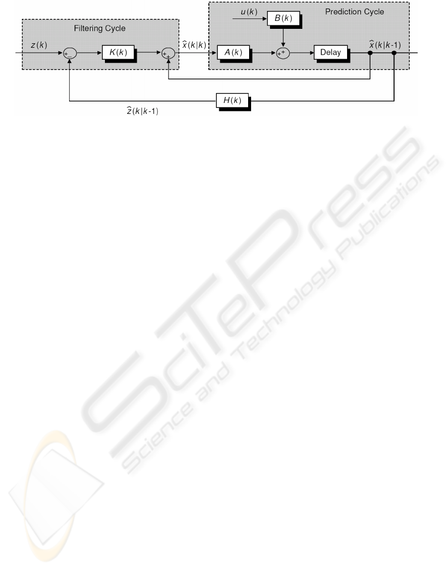
Figure 6: Block diagram representation of a Kalman filter.
u - is the control inputs
z - is the observation vector
K - is the filter gain
A - is the coefficient matrix of the system
B - is the driving matrix
H - is the measurement matrix.
The hat (^) scripts in figure 6 denote the criteria
of trying to minimize the RMSE of estimation. The
discrete time notation used in figure 6, k|k-1,
indicates that the estimate at k was determined given
knowledge at k-1. The filter gain is defined as
follows:
K(k) = P(k|k-1)H
T
(k)(H(k)P(k|k-1)H
T
(k) + R)
-1
(9)
where,
P - is the covariance matrix of state estimates
R - is the measurement noise covariance
matrix.
The matrices (P(k|k-1)) and (P(k|k)) for a Kalman
filter are given below as:
P(k|k-1) = A(k)P(k-1|k-1)A(k)
T
+ Q (10)
P(k|k) = (I - K(k)H(k))P(k|k-1) (11)
where,
Q - is the system noise covariance matrix
I - is the identity matrix.
It should be noted that the system noise covariance
(Q) and measurement noise covariance (R) matrices
may be time-variant, however we assume them here
to be constant. As shown in figure 6, a Kalman filter
of any type involves the recursive application of
prediction and filtering cycles. Brown and Hwang
(1992) give a complete derivation of the Kalman
filter algorithm.
To employ a Kalman filter for clamp force
estimation in a BBW system, we firstly use (6) as
our state space system equation. The constant α
0
from (6) is taken to be equal to A(k) from figure 6.
Note that typical matrix notations were not required
due to the unit state space dimension of (6). The
clamp force in (6) is non-linearly proportional to the
motor angle input. This non-linearity does not
require the use of an EKF because it is not state
dependent. To integrate this non-linearity within the
Kalman filtering algorithm given in figure 6 we
apply the following equality:
)(θα+)(θα+)(θα= )()(
1
2
2
3
3
kkkkukB
mmm
(12)
We take the equivalent of
)|( 1-kkx
from figure 6 to
be directly equal to
)|( 1-kk z
ˆ
, that is:
(13)11 ).|(=)|( -kkF-kkz
ˆ
cl
For this situation H(k) is taken to have a constant
unit value. We use (7) as our source for
measurement updates which is equivalent to z(k)
from figure 6. Saric et al. (2007) found that the
RMSE’s associated with (6) and (7), after having
adapted parameters, were 0.35 and 0.61 kN
respectively. These values squared are used for
assumed constant system (Q) and measurement (R)
error variances (the typical term covariance has not
been used since (6) has a unit state space
dimension).
With the Kalman concept to estimate clamp
force in BBW systems defined, the next section
briefly describes the test rig required to obtain
necessary data for analysis and subsequent
validation purposes.
A KALMAN FILTERING APPROACH TO ESTIMATE CLAMP FORCE IN BRAKE-BY-WIRE SYSTEMS
253
4 EXPERIMENTAL
ENVIRONMENT
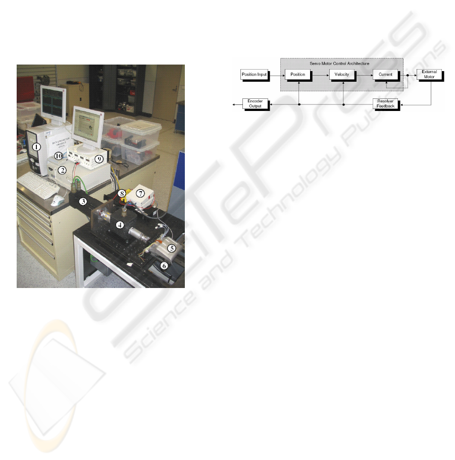
A test rig was setup for use on a prototype EMB
caliper. An external servo motor was used to provide
actuation by coupling it to the caliper internal
reduction gearing as shown in figure 7. The external
motor is of the permanent magnet brushless type,
with ratings of 55.5 N.m and 5, 000 rpm and ensures
that maximum clamp forces can be achieved. To
interface with this motor, the RS232 protocol was
utilized. MATLAB’s Simulink package along with
the xPC block-set provided a real time operating
system that was implemented to control the external
Figure 7: Test rig using a brushless permanent magnet
external servo motor.
1. host PC
2. target PC
3. brushless permanent magnet external servo
motor
4. external torque sensor
5. EMB caliper
6. external clamp force sensor
7. National Instruments brake-out boxes
8. low pass filter/amplifier for external clamp
force sensor
9. DC power supply
10. ethernet hub
motor angle. The external motor is controlled by
PID controllers within a standard motion control
architecture; cascaded position, velocity and current
control loops as illustrated in figure 8. Sensory
information are logged by uploading the signal data
to the host PC from the target PC, marked 1 and 2
respectively in figure 7. The logged data is stamped
at 100 μs time-step intervals. Both the host and
target PC’s have Pentium 4 processors operating at
2.4 GHz. To measure the caliper motor angle, an
encoder output is taken from the 1:1 coupled
external servo motor. The resolution of this encoder
output provides 8, 192 counts per revolution. An
external torque sensor is used to sense torque input
to the EMB caliper. An external clamp force sensor
is used to measure the true load induced by the brake
pads.
Figure 8: Control scheme used for external servo motor.
For the reasons of clarity the external motor
angle and torque data from this test rig is considered
to be received from an EMB caliper itself since a
resolver and current sensors are available.
5 RESULTS AND DISCUSSIONS
After having adapted parameters in (6) and (7) as
detailed by Saric et. al. (2007) and described
previously, the Kalman filter setup given earlier for
clamp force estimation purposes in a BBW system
are applied to uniform random data. The uniform
random data involves varying the motor angle in a
uniform random manner with a sample time of 100
ms. We use the constant system (Q) error variance to
initialize the clamp force estimate error variance at
time equal to zero.
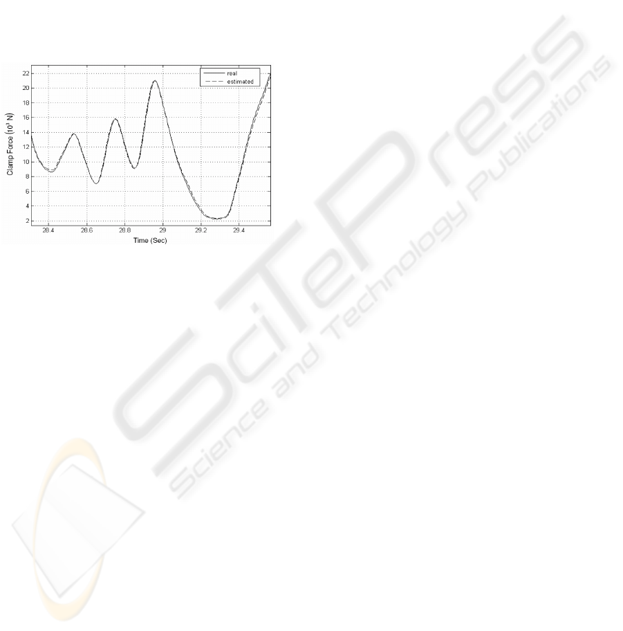
Figure 9 shows the performance of our new
method to estimate clamp force in a BBW system.
This result shows that adaptation to ABS controls is
possible seeing as the actuation speeds are
comparable. A new RMSE of 0.29 kN results which
is an approximately 20 % improvement on the
RMSE from the dynamic stiffness model alone.
Saric et al. (2007) found that the use of a maximum
likelihood estimator with no recursive aspect, as
given by (8), gave a RMSE in clamp force
estimation of 0.32 kN where the same experimental
setup and control input was used as here. Therefore
we have demonstrated that the use of an Kalman
filter which has a recursive aspect, improves the
ICINCO 2007 - International Conference on Informatics in Control, Automation and Robotics
254
RMSE of clamp force estimation by approximately
10 % with regards to the methods used by Saric et.
al. (2007).
With in-service pad temperatures being able to
possibly reach 800
O
C, it has been found that the
stiffness of pads varies depending on the
temperature (Schwarz et. al. 1998). Stiffness is a
large component within the clamp force estimator
developed within this paper. The brake pad
temperature was kept constant using the static test
rig shown in figure 8, and hence temperature effects
on clamp force estimation under practical
circumstances should be investigated.
Figure 9: Uniform random data, 100 ms sample time, EKF
clamp force estimator validation.
6 CONCLUSIONS
This paper presents the use of a cost effective and
design friendly solution for an automotive BBW
actuator. The objective of making a clamp force
sensor a redundant component in an EMB system is
strongly encouraged by the results within this paper.
A dynamic stiffness model was used to estimate
clamp force which relied on the output from an
internal resolver. Based on a torque balance
approach, a second model was used to estimate
clamp force which relied on the use of internal
motor current sensors and an internal resolver. Wear
dependent parameters from both models were
adapted using an in-service method. The outputs
from the two independent models were fused using a
Kalman filter to give optimized estimates of clamp
force. The developed estimator has been shown via
experimental verification to be able to handle highly
dynamic braking situations. Also it has been shown
that the RMSE of estimation with regards to
previous attempts to estimate clamp force in BBW
systems has been improved upon. With continued
development the possible cost savings inherent with
attempting to make a clamp force sensor redundant
can be accomplished in future EMB designs.
ACKNOWLEDGEMENTS
The initiative formed by the centre of Research for
Advance By-Wire Technologies (RABiT) provided
a medium for which this collaborative work was
undertaken by Swinburne University of Technology
(SUT) and PGT. The authors of this paper would
like to thank the engineers from PGT for their kind
assistance.
REFERENCES
Brown, R.G., Hwang, P.Y.C., 1992. Introduction to
Random Signals and Applied Kalman Filtering, John
Wiley & Sons. United States, 2
nd
edition.
Hoseinnezhad, R., Saric, S., Bab-Hadiashar, H., 2006.
Estimation of Clamp Force in Brake-by-Wire
Systems: A Step-by-Step Identification Approach,
SAE Technical Paper Series, no. 061154.
Kalman, R.E., 1960.
A New Approach to Linear Filtering
and Prediction Problems, ASME Journal of Basic
Engineering, vol. 82, ser. D, pp. 35-45.
Krishnan, R., 2001. Electric Motor Drives, Prentice Hall,
New Jersey.
Line, C., Manzie, C., Good, M., 2004. Control of an
electromechanical brake for automotive brake-by-wire
systems with adapted motion control architecture, SAE
Technical Paper Series, no. 042050.
Olsson, H., Åström, K.J., Wit, CCd., Gäfvert, M.,
Lischinsky, P., 1998. Friction models and friction
compensation, European Journal of Control, vol. 4,
no. 3, pp. 176-195, 1998.
Saric, S., Bab-Hadiashar, A., Hoseinnezhad, R., 2007. A
Sensor Fusion Approach to Estimate Clamp Force in
Brake-by-Wire Systems, IEEE Transactions on
Vehicular Technologies, accepted for publication.
Saric, S., Bab-Hadiashar, A., Hoseinnezhad, R., 2006. A
Sensor Fusion Approach to Estimate Clamp Force in
Brake-by-Wire Systems, IEEE Vehicular
Technologies Conference, no. 27448.
Schenk, D.E., Wells, R.L., Miller, J.E., 1995. Intelligent
Braking for Current and Future Vehicles, SAE
Technical Paper Series, no. 950762.
Sorenson, H.W.,
1970. Least-squares estimation: from
Gauss to Kalman, IEEE Spectrum, vol. 7, pp. 63-68.
Schwarz, R., Isermann, R., Böhm, J., Nell, J., Rieth, P.,
1999. Clamping force estimation for a brake-by-wire
actuator, SAE Technical Paper Series, no. 990482.
Schwarz, R., Isermann, R., Böhm, J., Nell, J., Rieth, P.,
1998. Modelling and Control of an Electromechanical
Disk Brake, SAE Technical Paper Series, no. 980600.
A KALMAN FILTERING APPROACH TO ESTIMATE CLAMP FORCE IN BRAKE-BY-WIRE SYSTEMS
255
