
NAVIGATION SYSTEM FOR INDOOR MOBILE ROBOTS BASED
ON RFID TAGS
Toshifumi Tsukiyama and Atsushi Suzuki
School of Information Environment,Tokyo Denki University, Inzai, Chiba, Japan
Keywords:
Mobile Robot, Navigation, RFID Tag, IC Memory, Landmark, Topological Map.
Abstract:
A new navigation method is described for an indoor mobile robot. The robot system is composed of a Radio
Frequency Identification (RFID) tag sensor and a commercial three-wheel mobile platform with ultrasonic
rangefinders. The RFID tags are used as landmarks for navigation and the topological relation map which
shows the connection of scattered tags through the environment is used as course instructions to a goal. The
robot automatically follows paths using the ultrasonic rangefinders until a tag is found and then refers the
next movement to the topological map for a decision. Our proposed technique would be useful for real-world
robotic applications such as intelligent navigation for motorized wheelchairs.
1 INTRODUCTION
This paper describes a navigation system for mobile
robots which are assumed to move autonomously to
a given goal in man-made environments such as hall-
ways in a building. A key function of the navigation
system is to choose a direction to a goal at a particular
place such the intersection of two hallways in a build-
ing. The navigation system requires a mechanism for
recognizing such particular places in the building and
locating them on a world map that gives course direc-
tions to a goal.
Two common approaches to robot navigation are
metric-based and landmark-based navigation (Mur-
phy, 2000). Metric-based navigation relies on met-
ric maps of the environment, resulting in naviga-
tion plans such as move forward five meters, turn
right ninety degrees and move forward another eight
meters. For position-sensing schemes, this ap-
proach relies on dead-reckoning based on informa-
tion about the motion of the robot derived from the
wheel encoders, or absolute position estimation us-
ing the global positioning system (GPS) (Hofmann-
Wellenof, 2003). These metric data are, however,
likely to be corrupted by sensor noise and this naviga-
tion method is vulnerable to inaccuracies in position
estimates.
To avoid reliance on error-prone metric data,
an alternative approach is landmark-based naviga-
tion. Landmark-based navigation relies on topolog-
ical maps whose nodes correspond to landmarks (lo-
cally distinctive places) such as corridor junctions or
doors. Map edges indicate how the landmarks con-
nect and how the robot should navigate between them.
A typical landmark-based navigation plan might be
to move forward to the junction, turn into the corri-
dor on the right, move to its end, and stop. This may
involve a complete absence of metric data and then
the method does not depend on geometric accuracy
(Kawamura, 2002). It has apparent analogies with hu-
man spatial perception, so it is easy to make a map of
the environment. In addition, topological representa-
tions avoid the potentially massive storage costs asso-
ciated with metric representations.
One problem to be solved in this method is to
decide what are suitable for landmarks in the envi-
ronment. Landmarks should be a distinctive one and
easy to recognize without special costs. In a building
intersections, corners and doors are very important
places for navigation and they could be a landmark.
However, they are often repetitively similar and suf-
fer from problem of occasionally sensors not being
able to distinguish between similar landmarks, such
as different doors of the same size. This can lead to
298
Tsukiyama T. and Suzuki A. (2007).
NAVIGATION SYSTEM FOR INDOOR MOBILE ROBOTS BASED ON RFID TAGS.
In Proceedings of the Fourth International Conference on Informatics in Control, Automation and Robotics, pages 298-304
DOI: 10.5220/0001644002980304
Copyright
c
SciTePress
both inefficiency and mistakes. Although such land-
marks with an artificial sign could be reliable and use-
ful, painted marks on walls would require special im-
age processing to extract them from the scene. This
would entail a complicated and costly process.
Therefore, we propose a method using Radio Fre-
quency Identification (RFID) tags as a sign. The
RFID tags are a passive, non-contact, read-only mem-
ory system based on electromagnetic wave and can
store a unique number for identification of the loca-
tion. The tags allow the acquisition of location infor-
mation at remarkable speeds without any distance in-
formation and the accurate control of robot positions
for sensing landmarks. Micro-processors with a wire-
less modem may be possible to give location infor-
mation as a landmark (Fujii, 1997). Although they
have the ability to handle data processing, they need
an on-board power supply like a battery. Landmarks
should be embedded in the environment and offer a
virtually unlimited operational lifetime. The passive
RFID tags operate without a separate external power
source and obtain operating power generated from the
reader. The tags are consequently much lighter, thin-
ner and less expensive than the active devices with a
microprocessor. The RFID tags can give enough lo-
cation information to achieve the robustness and effi-
ciency of navigation.
2 RFID TAGS AS LANDMARKS
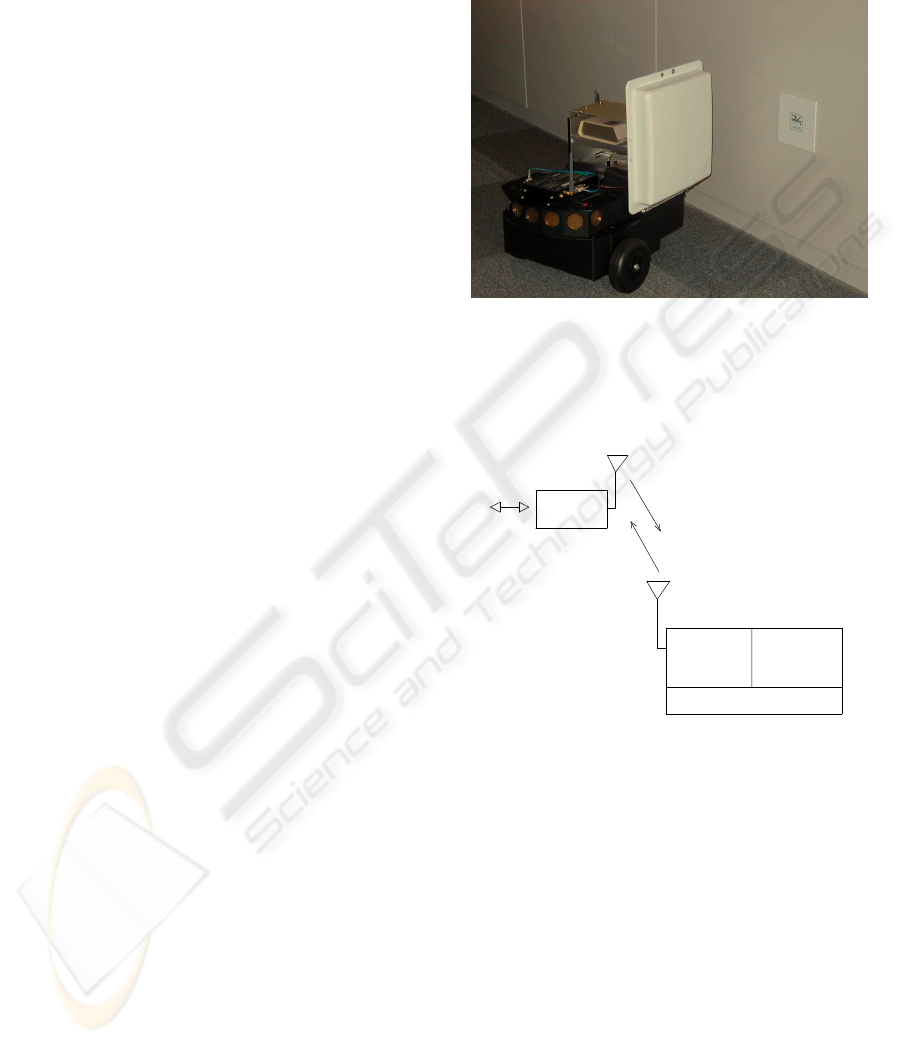
Figure 1 shows an RFID tags and the antenna box
of the RFID tag sensor system on a mobile robot.
The RFID tag (shielded in a 12 cm square plastic
plate) is an IC memory (115 Bytes) with a built-in an-
tenna, which is pasted on walls at particular places in
a building. Each IC memory has a unique ID number
which can provide information on its location within
the building. Figure 2 illustrates the way to get ID
number in a tag through the RFID tag sensor system
on the robot. The RFID tag sensor consists of an RF
transceiver and an antenna. The RF transceiver illu-
minates an RFID tag with a short pulse of electro-
magnetic waves (2.45 GHz, 0.3 w). The tag receives
the RF transmission, rectifies the signal to obtain DC
power, reads its memory to get the ID number, and
modulates the antenna backscatter in response to the
interrogation. The RF transceiver obtains the ID num-
ber and reports it to the navigation system running
on a Linux computer through an RS-232c serial port.
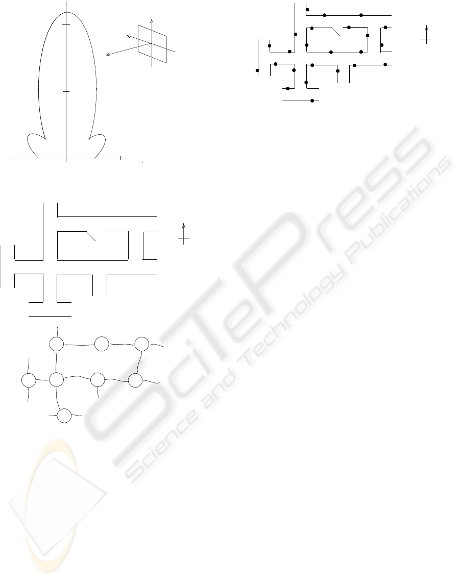
Figure 3 illustrates the sensitivity map of the RFID
tag sensor system. Since the induction area of a tag
is 40 cm wide and 100 cm depth from the antenna the
robot does not need precise positioning mechanisms
to locate and access the tags. The robot just passes by
tags without the accurate control of position for sens-
ing their numbers.
Figure 1: RFID tag pasted on a wall (white panel on right)
and the antenna of a RFID tag sensor mounted on a mobile
robot.
Wireless
Comunications
Memory
(ID Number)
Antenna
Electromagnetic
Wave (2.4GHz)
Energy
RFID Tag
(Transponder with no Battery)
RF Transceiver
with Decoder
Data
DC Power Generator
RS232c
Figure 2: Architecture of the RFID tag sensor system.
3 MAP FOR NAVIGATION
Figure 4(a) shows an example of a floor plan in a
building. The letters a, b, c, d, e, f, g, and h in the
floor plan denote the intersections of two hallways,
the junctions or near the door, which can be a par-
ticular place for a mobile robot. At these places the
robot has to choose an action to reach a given goal;
left-turn, right-turn, straight ahead, U-turn or stop if
the place is the destination. The robot repeats one of
these actions at every particular place. The particular
places can be considered a sub-goal. Global tasks (i.e.
NAVIGATION SYSTEM FOR INDOOR MOBILE ROBOTS BASED ON RFID TAGS
299
40 cm
100
50 cm
40 cm
z
x, y
y
x
z
Antenna of RFID tag sensor
Figure 3: Sensitivity range of the RFID tag sensor system.
a
b
c
d
N
e f
(b)
a
c
d
b
fe
g
h
g
h
(a)
door
passage
Figure 4: Example of a floor plan (a) and its topological
map (b).
going to a distant goal) require a world map for de-
ciding a sequence of sub-goals to a given goal. Figure
4(b) describes the topological relation of these partic-
ular places in the building. The nodes of the graph
with a letter correspond to the particular places such
as an intersection in the floor plan, respectively. An
edge between two nodes denotes that a hallway ex-
ists and a robot can pass along it to the next particular
place. Using graph search techniques you can gener-
ate a sequence of particular places to lead the robot to
a given goal, if a starting node is given on the graph.
The topological relation of particular places through
hallways can be used as a world map.
To distinguish particular places in the building we
1
2
3
4
6
7
8
9
10
11
12
13
14
5
15
16
17
18
a
b
c
d
N
e
f
g
h
(a)
19
20
2122
23
24
Node c
Direction Node Tag ID
N d 8
E h 9
S b 10
W a 7
Node d
Direction Node Tag ID
N ? 12
E e 13
S c 11
W -- --
S
E
W
(b)
Figure 5: Configuration of RFID tags for the floor plan (a)
and examples of the data structure of a node (b).
use the RFID tags. The tags are pasted on the left side
walls near the intersections of two hallways, the junc-
tions or doors. Actually, it is very difficult to paste
a tag precisely in a fixed position in a hallway or to
measure its position. The role of tags is to give just
information that the robot is coming upon an intersec-
tion and what the name of the intersection is. Figure
5(a) illustrates the configuration of the tags in the floor
plan. The dots near particular places show the posi-
tions of RFID tags and the numbers are an ID number
which the navigation system uses to identify upcom-
ing intersections in the robot path. The scattered tags
through hallways are used as a cue to decide the next
action. In our scenario the robot moves along the left
side of hallways finding tags and then the navigation
system recognizes the robot’s location on a world map
based on the tag’s ID number and decides the next
movement of the robot toward a given goal.
In path planning the navigation system must de-
cide a travel direction to the next sub-goal at an in-
tersection. To do this the order of the adjacent edges
which join at a node should be explicitly described
in the world map. In other words this means to de-
scribe on the map which hallway is on the left or right
side with respect to one hallway. One possible way
is to draw up a list of hallways in the data structure
of each node, maintaining the clockwise order of the
hallways. However, this is likely to confuse the order
when you trace the topological map from an entire
floor plan. In our scenario robots pass through hall-
ways in a building. They are usually intersected like
ICINCO 2007 - International Conference on Informatics in Control, Automation and Robotics
300
a cross. Therefore, we use compass points such as
North (N), South (S), East(E), West (W) for a rule of
the notation of directions. When you make a world
map, first, you should assign the North direction on
the floor plan for the reference bearing.
The data structure of a node include the list of ad-
jacent nodes with a compass point and tag ID numbers
which a robot will find coming to a particular place.
Figure 5(b) illustrates examples of the data structure
of a node of the graph. The mark ”–” in the node d
denotes there is no hallway in this direction, because
the node d is a junction. The mark ”?” means that a
hallway exists but the name of an adjacent node is un-
known at the moment. If a robot finds a tag with the
ID number 9 in a hallway, for example, the navigation
system searches all the node data of the graph for the
tag number and then finds it is in the data structure
of the node c. Consequently, the navigation system
recognizes the robot is coming into the intersection
c from the East side. Suppose that the next sub-goal
is the junction d, the navigation system searches the
node c for the next node direction. It finds that the
node d is adjacent to the node c and the direction is
the North. The robot is coming from the East side,
turns to the right at the intersection and going out to
the North side. Finally it will find another tag with
the ID number 11. This process is repeated until the
robot finds the goal.
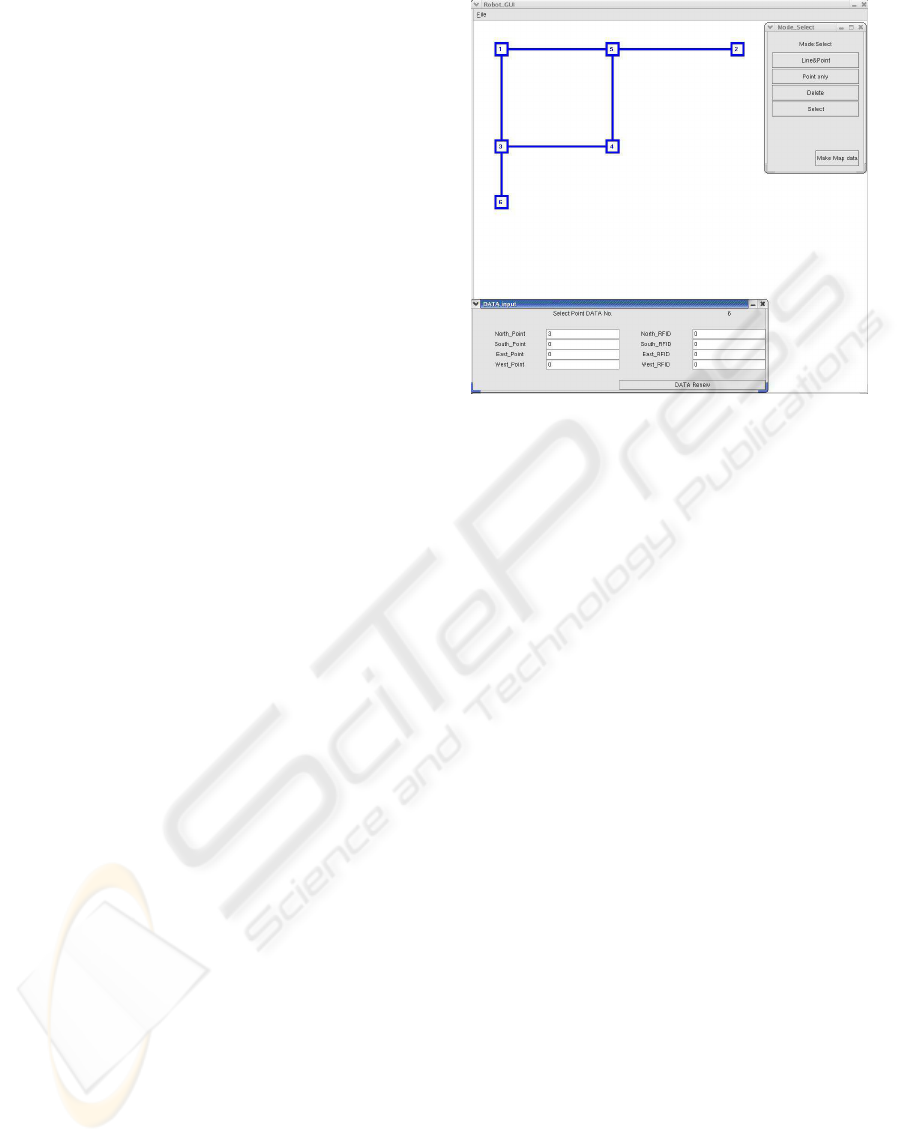
We have developed an interactive system for mak-
ing the database of map information from a floor plan.
The system was built up on a Linux computer with the
graphical toll kit GTK+ and the graphical user inter-
face (GUI) is shown in Figure 6. The small window in
the upper right corner displays the menus for editing.
The main window is used to draw the topological con-
nection of intersections and junctions the robot can
pass through. First, the user assigns the North direc-
tion on the floor plan for the reference bearing. The
mouse button is clicked on the screen and the mouse
is dragged in one of the four directions (North, South,
East or West), then two nodes with an edge is dis-
played and the data structures for the nodes as shown
in Figure 5(b) are created in the system. After this the
mouse button is clicked on one of the nodes and the
mouse is dragged to extend the graph. Next, the user
changes the editing mode to compile the data struc-
ture of a node and clicks each node on the screen.
Then another small window (in the lower left corner)
appears to input the RFID tag numbers which are set
near the node. This process is repeated for every par-
ticular place on the floor plan. Finally, the user selects
the menu to save the database in a file, which the robot
can use for path planning.
Figure 6: Interface for tracing a map.
4 ROBOT SYSTEM
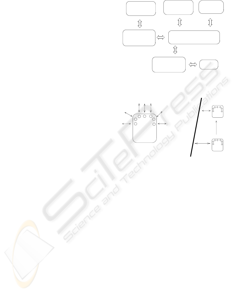
Figure 7 illustrates the architecture of the navigation
system. The system mainly consists of a navigation
planning module, a graphical user interface (GUI) for
tracing maps and a database of map information. The
GUI as shown in Figure 6 enables us to make the
database of map information from a floor plan. The
database is a set of the data structure of nodes shown
in Figure 5(b), which shows the relation of the par-
ticular places of the floor plan and assigned RFID
tag numbers to each particular place. The navigation
planning module decide a route to a given goal from
sensed RFID tag numbers and the map information.
The navigation system was implemented on a host
computer running on Linux and the mobile robot
shown in Figure 1. The host computer manages the
functions of the navigation planning module shown in
Figure 7. The computer has two wireless RS-232c se-
rial ports. It is responsible for handling the data from
the RFID tag sensor through a wireless serial port and
sending commands to the motor control module on
the micro-controller of the mobile robot through an-
other wireless serial port. The robot consists of a mo-
bile platform and an RFID tag sensor. The mobile
platform (approx. 35 cm square) is equipped with an
on-board micro-controller, a two-wheel drive system
with one rear free wheel, an odometer with optical en-
coders, seven ultrasonic rangefinders and an RS-232c
serial port. The rangefinder units are mounted at the
front of the robot as shown in Figure 8(a) for forward
and lateral sensing and the sensitivity range is up to
5 meters. The micro-controller manages the motion
control module for running the drive system and col-
NAVIGATION SYSTEM FOR INDOOR MOBILE ROBOTS BASED ON RFID TAGS
301
lecting position and speed information from the drive
encoders, including firing the sonar sensors and re-
trieving echo signals.
In our method the precise positions of RFID tags
in a hallway is not known. Also, the robot is not
aware of the length of hallways. The robot just fol-
lows the left side walls of the hallway until it finds
a tag. It is essential that an mobile robot be able to
realign itself relative to a wall and then proceed if it
becomes disoriented. Man-made environments such
as hallways are usually constructed with a horizontal
plane (a floor area) and vertical planes (walls, pillars
and doors). The boundary line formed by the floor
and a wall becomes a long straight line which can be
seen at any point in the scene. Since the RFID tags
are pasted on vertical planes, the walls, the boundary
lines can be used as a guide for navigation. The geom-
etry of sensing the distance to a wall and measuring
the orientation of the robot with respect to the wall
is shown in Figure 8(b). The robot is equipped with
seven rangefinders as shown in Figure 8(a). The lat-
eral rangefinder views the left side wall at two points
and measure the distance (d1, d2) to the wall. The
orientation of the robot with respect to the wall is cal-
culated from the difference of the distances and the
moving distance L.
Figure 9 shows the flow of motion control for the
robot. The rangefinders are invoked every few meters
of movement and generate the angle formed by a wall
and the robot’s direction and the perpendicular dis-
tance to the wall from the robot. The navigation plan-
ning module uses these data to change the orientation
of the robot parallel to the wall and drives it along the
wall maintaining the distance between the robot and
the wall. The rangefinders also check for sudden ob-
stacles for emergency stops. If a tag is detected while
the robot is moving the navigation planning module
recognizes the robot’s location on the topological map
from the ID number and then decides the next direc-
tion: the robot turns to the left, turns to the right, goes
ahead or turns back. When changing the direction at
an intersection the movement is controlled mainly by
the rangefinders. The robot moves forward measuring
the distance to both side walls with the rangefinders
and find the center of the intersection from the mea-
sured distance. At the center the distance becomes
huge because of no walls. Then, the robot turn to the
indicated direction. After the robot passes an intersec-
tion the rangefinders are invoked again and the robot
follows another hallway until it finds a tag.
RFID Tag
Sensor Module
Navigation Planning Module
Motor Control
Module
Graphical
User Interface
Sonar
Rangefinder
Odometer
Database of
Map Information
Figure 7: Architecture of the navigation system.
Front of robot
(a)
d1
d2
L
Direction
of ultrsound
Wall
(b)
Figure 8: Sonar positions (a) and measuring the orientation
of the mobile robot(b).
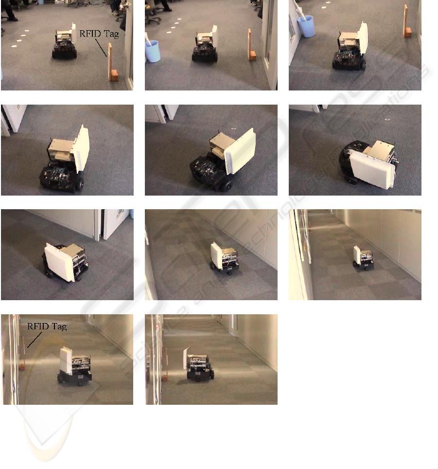
5 EXPERIMENTAL RESULTS
A typical test run of the mobile robot based on the
navigation method is shown in the series of pho-
tographs in Figure 10. The sequence shows the robot
starts near an RFID tag, orients itself in a junction and
then traveling until it finds another RFID tag. This
movement is similar to one along the route from the
tag number 23 to 19 in Figure 5(a). The width of the
passage was 1.6 m and the traveling distance along
the passage was about 8 m. As shown in Figure 10(a)
a tag was fixed on the low pole near the exit to a pas-
sage. Figure 10 (b) shows that the robot passed by the
tag and the tag’s ID number was detected by the RFID
tag sensor. The navigation planning module decided
next movement based on the tag’s ID number. In this
test run the robot was scheduled to turn to the right.
The robot moved for a while under the control of
the odometer of the robot and then checked if the right
side of the robot is a free space (i.e. no walls) using
the ultrasonic rangefinders. This process was repeated
until an enough space was found on the right side (see
ICINCO 2007 - International Conference on Informatics in Control, Automation and Robotics
302
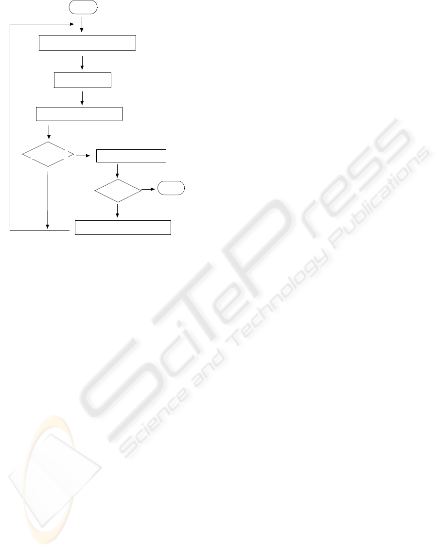
Start
Measure Distance to Walls
Check RFID Tag Number
Check Route Map
Tag No. > 0
Decide Direction and Move
End
Goal ?
Follow Passage
Yes
Yes
Figure 9: Flow of the navigation method.
Figure 10(c) and (d)). After that the robot turned to
the right as shown in Figure 10(e) and (f). The robot
moved along the passage (see Figure 10(g), (h) and
(i)) and after every 1 m of movement, the rangefinder
module was invoked. From the geometrical informa-
tion the navigation planning module decided the ro-
tation angle of the robot to reorient the robot parallel
to the wall, and the distance needed to draw the robot
near to the wall. To sense the RFID tags reliably the
robot must move along the wall at a distance of less
than 1 m. In this experiment the distance was 0.8 m.
The sensor guidance with iterative sensing and mo-
tion continues until an RFID tag is found. In Figure
10(j) the robot suddenly faced the wall obliquely due
to slip or something. The navigation plan module at-
tempted to reorient the robot parallel to the wall (Fig-
ure 10(k)). After that, another RFID tag was detected
and the robot stopped.
6 CONCLUSIONS
Mobile robots are a very imprecise mechanism. Navi-
gation systems for mobile robots should have a mech-
anism to accomplish tasks with an adequate degree of
precision. We thus proposed a topological navigation
system using RFID tags and a sonar rangefinder sys-
tem. The rangefinder was used to reorient the robot
parallel to a wall keeping the distance to it. We also
introduced a topological connection map of the RFID
tags, which can be built without precise 3-D represen-
tation of the environment. Robots just follow the tags
under instructions of the topological map. The equip-
ment setup is very simple and the navigation system
is easily combined with the robot’s computer systems.
This is both practical and acceptable for the applica-
tion of mobile robots to the real world.
A graphical user interface for making the world
map conveniently is indispensable for the application
of the navigation method. We have built an interac-
tive system running on the Linux. This is an on-going
project.
REFERENCES
Murphy, R. R. (2000). Introduction to AI Robotics. MIT
Press.
Hofmann-Wellenhof, B and et al. (2003). Navigation - prin-
ciples of positioning and guidance. Springer.
Fujii, T. and et al.(1997). Intelligent Data Carrier System
for Cooperative Behaviors Emerge among Collective
Robots. Proc. of IEEE International Conference on
Systems, Man, and Cybernetics, Vol. 1, pp. 299-304.
Kawamura, k and et. al.(2002). Toward Perception-Based
Navigation Using EgoSphere. Proc. of SPIE, Vol.
4573, pp. 137-147.
NAVIGATION SYSTEM FOR INDOOR MOBILE ROBOTS BASED ON RFID TAGS
303
(a) (b) (c)
(d) (e) (f)
(g) (h) (i)
(j) (k)
Figure 10: Test run of the mobile robot.
ICINCO 2007 - International Conference on Informatics in Control, Automation and Robotics
304
