
A NOVEL STRATEGY FOR EXPLORATION WITH MULTIPLE
ROBOTS
Jonathan Rogge and Dirk Aeyels
SYSTeMS Research Group, Ghent University, Ghent, Belgium
Keywords:
Multi-robot systems, coverage, exploration, demining.
Abstract:
The present paper develops a novel strategy for the exploration of an unknown environment with a multi-
robot system. Contrary to most exploration problems, the topographical properties of the space need not be
mapped. The algorithm we propose is inspired by methods used for complete coverage of an area, where all
free space has to be physically covered by all robots. In the present paper it is required that the entire free
space is covered by the sensors of the robots, with a certainty of 100%. This weaker requirement enables us
to scan more space in less time, compared to complete coverage algorithms. Moreover the shape of the robot
formation adjusts itself to situations where obstacles, narrow spaces, etc. have to be passed. Communication
between the robots is restricted to line-of-sight and to a maximum interdistance between robots. A direct
application of the algorithm is mine field clearance.
1 INTRODUCTION
The research domain of multi-agent robot systems
can be divided into subdomains according to the task
given to the robot group (Ota, 2006). At present well-
studied subdomains are motion-planning (also called
path-planning), formation-forming, region-sweeping,
and combinations of the foregoing. The problem con-
sidered in the present paper belongs to the discipline
comprising region-sweeping. In this discipline two
different robot tasks are usually considered.
In the first task a group of robots receives the order
to explore/map an unknown region. The goal is to ob-
tain a detailed topography of the desired area. A typ-
ical approach to tackle the above problem with mul-
tiple robots assumes unlimited communication (Bur-
gard et al., 2005): since exploration algorithms are
already devised for a single robot it seems straight-
forward to divide the area to be explored into disjunct
regions, each of which is assigned to a single robot.
The robots communicate to each other the area they
have explored so that no part of the free space will be
explored twice unnecessarily. At no point during the
task are the robots trying to form a fixed formation.
Each robot explores a different part of the unknown
region and sends its findings to a central device which
combines the data received from the robots into one
global map of the area.
Closely related to the exploring/mapping task is
the second task, called complete coverage, where the
robots have to move over all of the free surface in
configuration space. Typical applications are mine
field clearance, lawn mowing and snow cleaning. The
coverage problem has been addressed in the litera-
ture both in a deterministic and a probabilistic setting.
In the probabilistic approach the robots are consid-
ered as if they were fluid or gas molecules satisfying
the appropriate physical laws of motion (Kerr et al.,
2004), (Keymeulen and Decuyper, 1994). Just as a
gas by diffusion fills an entire space, the robots will
cover all free space when time tends to infinity. In
the remainder of the paper we focus on the determin-
istic setting. In this setting the robot group typically
forms (partial) formations to solve the task. Refer-
ence (Choset, 2001) gives a short overview of existing
techniques for multi-robot coverage problems. Dif-
ferent approaches to the coverage problem are found
in (Cort
´
es et al., 2004), (Kurabayashi et al., 1996),
(Wong and MacDonald, 2004), (Zheng et al., 2005)
(Rekleitis et al., 2004) and (Kong et al., 2006).
76
Rogge J. and Aeyels D. (2007).
A NOVEL STRATEGY FOR EXPLORATION WITH MULTIPLE ROBOTS.
In Proceedings of the Four th International Conference on Informatics in Control, Automation and Robotics, pages 76-83
DOI: 10.5220/0001645500760083
Copyright
c
SciTePress

The problem statement of the present paper
does not differ that much from the common explo-
ration/mapping task and the complete coverage prob-
lem, but is rather a combination of both. It is required
that all of the free space is sensed by the robots, but
not necessarily physically covered. However, unlike
the common exploration case, the sensing of the area
does not have as goal to map the topography of the
free space and the location of the obstacles in it. Our
aim is to locate several unknown targets within the
free space. Moreover, similar to the complete cov-
erage setting we demand a 100% certainty that all
free space has been covered by the sensors at the
end of the exploration procedure, implying that all
targets have been found. Since the robots no longer
have to cover all free space physically, the novel al-
gorithm will yield a time gain compared to complete
coverage strategies. The developed algorithm is in-
spired by complete coverage strategies as (Rekleitis
et al., 2004), (Kong et al., 2006). In these strategies
it is assumed that the space to be explored does not
have a maze-like structure with many narrow corri-
dors, but is an open space containing only convex
obstacles sparsely spread throughout. In the present
paper we adopt these assumptions, postponing more
complex geometries to future work. Our algorithm is
presented in Section 2 of the paper. A short compari-
son between the algorithm presented here and that of
(Rekleitis et al., 2004) is given in Section 3.
A specific application we have in mind is mine
field clearance using chemical vapor microsensors
(Gage, 1995). Once a landmine is deployed, the en-
vironment near the mine becomes contaminated with
explosives derived from the charge contained in the
mine. The vapor microsensors are able to detect the
chemical vapor signature of the explosives emanating
from the landmines from a distance. This implies that
complete coverage algorithms may be too restrictive
with respect to the demining problem. Performing the
algorithm of the present paper, with the weaker re-
quirement of sensor coverage, will result in a gain of
time.
The algorithm can also be used in problems where
a robot formation has to cross a terrain containing
sparsely spread obstacles. There is a natural trade-off
between coherence of the formation and avoidance of
the obstacles. The robot group is allowed to split in
order to pass the obstacles, resulting in faster progress
of the group across the terrain. The algorithm ensures
that once the obstacle is passed, the robots regroup.
2 AN ALGORITHM FOR
COMPLETE SENSOR
COVERAGE
2.1 Setting
Consider a population of N identical robots. Each
robot is equipped with two types of sensors. One type
serves as a means to detect the goal targets to be found
in the assigned area, e.g. landmines; the other type is
used to detect and locate other robots and obstacles
in the neighborhood of the robot
1
. Both sensors have
a maximum detection range s
t
and s
r
respectively. It
is assumed that targets which come within the radius
of the corresponding sensor area s
t
or s
r
of the robot
are always detected, and that if they are located far-
ther away than the distance s
t
,s
r
they are never de-
tected. The robot configuration allows limited com-
munication. First, this is expressed by the maximum
detection range s
r
as described above. Second, line-
of-sight communication is assumed: two robots can
only sense each other if they are sufficiently close to
each other and if there is no obstacle located on the
straight line connecting both robots.
Two robots are called connected to each other
when they sense each other. Every robot is assigned
an index number. The initial state of the robot con-
figuration is such that robot i is connected to robots
i− 1 and i+ 1, ∀i ∈ {2,...,N − 1}. (Robot 1 is only
connected to robot 2 and robot N is only connected
to robot N − 1.) An example of such a configuration
is depicted in Figure 1 for N = 6. The dashed circles
1
6
5
4
3
2
Figure 1: Overlapping sensor areas in a possible robot con-
figuration.
have radius s
t
and signify the sensed area for goal tar-
gets of each robot. It is assumed that
s
r
2
< s
t
< s
r
. (1)
1
In practice the latter type consists of two distinct mini-
mally interfering IR-sensors: one sensing obstacles and the
other sensing robots. Since this is not relevant for the the-
oretical description of the algorithm, these sensors are con-
sidered as if they are one and the same.
A NOVEL STRATEGY FOR EXPLORATION WITH MULTIPLE ROBOTS
77

The lower bound on s
t
in (1) ensures that the areas
sensed for goal targets of neighboring robots partially
overlap, as illustrated by Figure 1.
In a second step, we impose a preferred formation
on the robot group as follows: each robot keeps a con-
stant distance d < s
r
with its neighbors and observes
them at preferred angles with respect to its forward
direction. With notation from Figure 2, these angles
are defined by:
α
i
=
(
π/4, i even,
3π/4, i odd,
β
i
=
(
−π/4, i even,
−3π/4, i odd.
(2)
Furthermore each robot is equipped with a compass.
Together with the above defined angles, the forward
direction of each robot (the same for all robots) is im-
posed at the initialization of the algorithm. The above
conditions imply a robot formation with zigzag shape,
as shown in Figure 3. Once the preferred formation is
attained the scanning algorithm is started.
i + 1
α
i
i
i − 1
β
i
Figure 2: Defining the angles of the preferred robot config-
uration.
2.2 The Scanning Algorithm
Assume for simplicity that the area to be explored is
a rectangular subset S of R
2
. All obstacles contained
in S are assumed disjoint and convex. Divide the set
S into parallel (scanning) strips of width (
N
2
− 1)d.
This choice of the value of the width will be motivated
later, in Section 2.4. Furthermore assume that N and d
are such that all obstacles in S have a diameter smaller
than the width of a scanning strip. Fix the maximum
allowed diameter at (
N
2
− 3)d. The main idea of the
algorithm is to let the group of robots sweep the area
S strip after strip in a zigzag-like pattern. Clearly,
when there is a sufficient number of robots available
the set S can be regarded as one big strip, simplifying
the algorithm since no transitions between consequent
strips have to be performed.
In a first case we consider a strip where no objects
are located on the boundary (see Figure 3). Robots 1
and N are allocated the task to follow the boundaries
of the strip at a constant distance at the constant ve-
locity v. They can be considered leaders of the robot
group. These two leader robots do not try to stay in
the preferred formation, i.e. the condition on the cor-
responding angles α
N
,β
1
is removed, and they do not
maintain a fixed interdistance d with their neighbors.
The remaining robots, however, still maintain the pre-
ferred formation. When no obstacles are present in
the strip, the robots scan the strip for goal targets in
the above defined preferred (rigid) formation moving
at a velocity v.
Figure 3: A depiction of the algorithm. The arrows indicate
the constant velocity of both leader robots. The dashed lines
represent the strip boundaries.
When an obstacle is encountered the algorithm
aims to guide the robot group past it in a time-optimal
way. The leader robots start driving at a preset veloc-
ity v
0
< v (see Section 3); the group is split into two
subgroups in order to move around the obstacle. The
subgroups rejoin after passing the obstacle to resume
the preferred formation structure.
Assume for reasons of simplicity that the number
of robots N is even. Consider the situation where
robot m encounters an object on its path such that
it cannot stay in the preferred formation any longer.
More precisely, the sensors of robot m measure
• an interdistance between the obstacle and the
robot smaller than a preset distance d
o
< s
r
,
• the position of the obstacle at an angle with its
forward direction inside the interval (−γ,γ), with
γ a fixed value inside the interval (0,
π
4
).
The presence of the obstacle is communicated to all
the robots in the group. Each robot takes on a dif-
ferent role such that two subgroups will be formed.
The robots with index i ∈ S
1
:= {2,...,N/2} now
follow the neighboring robot with corresponding in-
dex i − 1. Similarly, robots with index i ∈ S
2
:=
{N/2 + 1, . . . , N − 1} follow the neighboring robot
with index i+ 1. More precisely, the robot with in-
ICINCO 2007 - International Conference on Informatics in Control, Automation and Robotics
78

Figure 4: A group of 10 robots passing an obstacle. Only robots 5, 6 and 7 apply wall-following around the obstacle during the
maneuver. This is shown in the second and third picture. The first picture shows the formation at the moment of encountering
the obstacle. The fourth picture presents the formation after having completely past the obstacle.
dex i tries to reach the following coordinates:
(
(x
i−1
+ dsin
π
4
,y
i−1
+ (−1)
i
dcos
π
4
), if i ∈ S
1
,
(x
i+1
− dsin
π
4
d,y
i+1
+ (−1)
i
dcos
π
4
), if i ∈ S
2
.
(3)
These coordinates are considered with respect to a
right-handed (x,y)-frame with the y-axis parallel to
the strip boundary, and directed into the driving di-
rection of the leader robots. Each robot still tries to
stay in the preferred formation, but in order to do so
only takes information of one neighbor into account.
Moreover, the condition on the relative position be-
tween the neighboring robots N/2 and N/2+ 1 is sus-
pended, which will lead to the splitting of the robot
group. Notice that indifferent of the robot that ob-
serves the obstacle first, the group will split between
robots N/2 and N/2 + 1. This choice is motivated in
Section 2.4.
Consider the situation for robot i where one of the
following occurs:
• The desired position (3) cannot be reached,
• The obstacle is blocking the straight path between
the present position of robot i and its desired po-
sition,
• Robot i does not detect its neighbor necessary to
determine its preferred position.
If this situation occurs, the robot receives the order to
follow the edge of the obstacle, keeping the obstacle
on its right if i ∈ S
1
, or its left if i ∈ S
2
. This be-
havior is called wall-following. The robot continues
to wall-follow around the obstacle until none of the
above conditions is satisfied. After that, it assumes its
desired position again. If all robots have past the ob-
stacle, each robot is again able to reach its desired po-
sition in the preferred formation. In particular, robots
N/2 and N/2+ 1 will meet again in their desired rel-
ative position. When this happens a signal is sent to
all robots with the message that the group has past the
obstacle.
A simulation of the above described algorithm is
presented in Figure 4 with N = 10 and m = 6.
Remark. It may occur that a robot cannot reach its
desired position because it is located too far away
from its present position. Then the robot simply rides
towards the desired position at the maximum allowed
velocity, trying to catch up.
Remark. If the number of robots N
∗
in the
(sub)group is not even, then the indices of the robots
where the robot group splits are ⌊N
∗
/2⌋ and ⌈N
∗
/2⌉,
where ⌊.⌋ is the function giving the largest integer less
than or equal to its argument, and similarly, ⌈ .⌉ gives
the smallest integer greater than or equal to its argu-
ment.
2.3 Multiple Obstacles
Suppose the robot group is already split into two sub-
groups and a robot in one of the subgroups encounters
a second obstacle. The above obstacle avoidance al-
gorithm can be made modular in order to solve this
problem. A group can only split if both robots at the
extremities of the group are leader robots, similar to
the initial configuration. Assume group S
1
encoun-
ters a second obstacle. Robot N/2 is then turned into
a leader robot. Instead of following a strip boundary it
is ordered to follow the edge of the first obstacle, un-
til it meets its neighbor N/2+ 1 or until group S
1
has
past the second obstacle. In the latter case, robot N/2
takes on its role as a follower of robot N/2−1 again,
in the former case it turns into a follower of N/2+ 1.
The group S
1
is split into the middle and the algo-
rithm described in the previous section is performed
with leader robots 1 and N/2. In order for each robot
to know which role to assume, it keeps track of how
many times its subgroup is split.
Clearly, the number of times this splitting can be
repeated is limited. We require a subgroup to consist
of at least 3 robots: two leader robots on each side
of the group, plus at least one robot in the middle at-
tempting to follow both leaders while maintaining the
formation structure. The middle robot ensures that the
A NOVEL STRATEGY FOR EXPLORATION WITH MULTIPLE ROBOTS
79

discs of sensed area of the separate robots overlap for
all time instants.
2.4 Adaptation of the Basic Algorithm
Consider a worst case scenario as sketched in Fig-
ure 5. The robot formation splits into two subgroups,
and the group on the left hand side moves through
the gap between the obstacle and the left boundary of
the scanning strip. Once past the gap the robots in
this subgroup have to spread out, since the distance
between the obstacle and the left boundary increases
and we want to sense all of free space between the
boundary and the obstacle. The obstacle has such a
shape that the robots have to spread out across almost
the entire width of the scanning strip before meet-
ing a robot member of the right subgroup. The basic
algorithm is modified as follows. When robot N/2
(resp. N/2+ 1) encounters the obstacle, it is now pro-
grammed to follow the obstacle’s edge until it meets
its neighbor N/2+ 1 (resp. N/2). Additionally, it en-
sures that its neighbor N/2− 1 (resp. N/2+ 1) stays
in its detection range by sending a signal to the other
robots of its subgroup to increase the angle π/4 of (3).
This changes the desired position of each robot in the
subgroup resulting in a stretching out of the group,
as far as necessary. The above modified algorithm
Figure 5: A depiction of the worst case scenario in the al-
gorithm.
justifies our choice of initial formation and width of
the scanning strip. If we had naively chosen a value
(N − 1)d as the width of a scanning strip, the initial
preferred robot formation would be able to span this
entire distance, namely by forming a line with the an-
gles defined in Section 2.1 equal to α
i
= −β
i
= π/2.
However, one subgroup, consisting of only half of the
number of robots, would not be able to span this dis-
tance, resulting in either an error message from the al-
gorithm or in unscanned areas, if a situation described
in Figure 5 was encountered.
Closely related to this observation is the choice to
split the robot group precisely in the middle. Since the
sensor range of each robot is limited and the robots
operate in an unknown environment, the shape of
each obstacle is unknown. To guarantee that the area
around the obstacle is fully covered by the sensors, we
have to supply a sufficient number of robots to both
sides of the obstacle. For instance, when the shape
of the obstacle in Figure 5 is known a priori, one can
decide to send more than half of the robots to the left
of the obstacle. Consider the case where the obstacle
is reflected with respect to the vertical axis. In this
case sending less than half of the robots to the right
would lead to uncovered areas or an error message in
the algorithm. With limited sensor information it is
not possible to discriminate between the situation of
Figure 5 and its reflected version. This leads us to
always split the group into two equal parts.
An alternative solution for this problem could be
a more intelligent algorithm where individual robots
transmit more sensor data to the others in order to find
possible bounds on the size of the encountered obsta-
cle. If the obstacle is small, a better way to split is
right at the place where the obstacle is encountered.
The robots do not have to deviate much from the pre-
ferred formation, which decreases the probability on
error messages from deforming the robot configura-
tion. This idea may be incorporated in future work.
2.5 Obstacles Located on the Boundary
between Two Strips
Throughout the paper the obstacles are assumed to
have a convex shape, in order to avoid robot groups
getting stuck in a dead end. However, there is one
case of dead ends we cannot avoid by the above as-
sumption. A dead end can occur when an obstacle is
located on the boundary between two strips, as pre-
sented on the left hand side of Figure 6. Since the
robots have limited sensor information, they cannot
conclude a priori whether an encountered obstacle
stretches out into a neighboring strip or not. We are
forced to let the algorithm run until a dead end is ob-
served.
Figure 6: Two situations where an obstacle is located on
the boundary between strips. On the left hand side a dead
end situation arises; on the right hand side one of the leader
robots guides the group around the obstacle.
ICINCO 2007 - International Conference on Informatics in Control, Automation and Robotics
80

Before tackling the dead end problem, let us treat
the case presented on the right hand side of Figure 6,
which does not lead to a dead end situation. Con-
sider an (x,y)-frame with the y-axis parallel to the
strip boundary, and directed into the driving direction
of the leader robots. When the leader robot encoun-
ters the obstacle, the algorithm assigns to this leader
a wall-following procedure around the obstacle. The
leader keeps the obstacle either on its right or left (de-
pending on its position in the robot formation) while
moving into the interior of the strip away from the
strip boundary. As can be concluded from the picture,
the y-coordinate of the leader increases while mov-
ing around the obstacle. We wish to keep the veloc-
ity component of the leader robot parallel to the strip
boundary equal to v. Since the robot deviates from
its straight path parallel to the strip boundary, this im-
plies it has to speed up. When the leader reaches the
strip boundary again, it switches back to the original
task of moving parallel to the boundary.
Now consider the left hand side of Figure 6. A
dead end is detected by the algorithm when two con-
ditions are satisfied:
• one of the leader robots cannot move into the de-
sired direction parallel to the strip boundary, be-
cause an obstacle is blocking the way.
• when the leader robot starts wall-following the
obstacle as described above, the value of its y-
coordinate decreases.
As soon as a dead end is observed by the leader robot,
it changes its behavior and stops its wall following al-
gorithm. Instead, it projects its corresponding strip
boundary (N/2− 1)d/8 units outwards and resumes
the original scanning algorithm with respect to the
new boundary. If the extra width turns out to be insuf-
ficient to guide the robot subgroup around the obsta-
cle outside of the original scanning strip, the bound-
ary is projected a second (third,...) time. This way the
subgroup which was stuck in the dead end is guided
around the obstacle. When both subgroups reestab-
lish contact, the leader robot returns to the original
strip boundary. This behavior is faster and easier to
implement than a turning-back scenario, where the
subgroup of robots which meets a dead end retraces
it steps to go around the obstacle inside the original
scanning strip.
Remark. The above situation with a solid wall as
strip boundary, forcing a turning-back maneuver, is
precluded.
2.6 The Transition from One Strip to
the Next
When the robot group reaches the end of a scanning
strip, it needs to be transported to the next strip. This
is done in a few easy steps. Consider the situation of
Figure 7. First the right leader changes its behavior
into that of a robot in the interior of the formation, i.e.
it tries to attain the desired formation. The left leader
moves (N/2 − 1)d units to the left perpendicular to
the strip boundary. The rightmost robot resumes its
leader role and all robots reverse their forward direc-
tion with respect to the desired direction in the previ-
ous strip. Naturally, every time the end of a strip is
reached, the roles of left and right leader alternate, so
that the robot group does not get trapped into a loop
consisting of two strips.
Figure 7: The robot group moves from the end of a scanning
strip to the start of the next strip.
3 COMPARISON WITH
COMPLETE COVERAGE
ALGORITHMS
The algorithm presented in this paper is inspired by
the complete coverage algorithm presented in (Rek-
leitis et al., 2004), which is depicted in Figure 8. The
authors of (Rekleitis et al., 2004) propose the follow-
A NOVEL STRATEGY FOR EXPLORATION WITH MULTIPLE ROBOTS
81
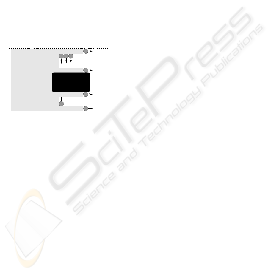
ing robot configuration: 2 leader robots, following
the strip boundaries, and a number of interior robots,
traveling back and forth between the strip boundaries
physically covering all the free space. Contrary to the
algorithm proposed in the present paper, the leader
robots maintain line-of-sight contact between each
other. When an obstacle appears between the two
leaders the line-of-sight contact is lost and the obsta-
cle is detected. An appropriate control action is then
taken by splitting the platoon and the algorithm is re-
peated on both sides of the obstacle. The splitting
procedure includes the creation of two extra leader
robots, as shown in Figure 8. Remark that the lead-
ers are allowed to move ahead of the rest of the robot
group and hence group coherence is not maintained
or desired, contrary to our approach.
Figure 8: A depiction of the complete coverage algorithm
by Rekleitis et al.
In the remainder of this section we will compare
speed of performance of the present algorithm with
the algorithm of (Rekleitis et al., 2004). In order to
do so, realistic distance values are considered. Chem-
ical vapor sensors detecting mines have a range s
t
=
1.70 m. Obstacles and other robots can be detected by
laser based sensors with a range of s
r
= 3.3 m such
that (1) is satisfied. Assume the robots themselves
possess a diameter of 0.3 m and set the fixed interdis-
tance d between neighboring robots in the preferred
formation equal to s
r
. With N the number of robots in
the group, this yields a strip width of 1.65(N − 2) m.
When no obstacles are encountered, the robots are
allowed to move at a preset maximum velocity v
max
.
In the algorithm of the present paper v
max
is directed
parallel to the strip boundary, whereas the interior
robots in (Rekleitis et al., 2004) travel back and forth
inside the strip at v
max
. It can be proven that for the
latter case with the values given above the speed of
progress parallel to the strip boundary is v
max
/6.
In the presence of obstacles a comparison is more
difficult. First consider the complete coverage algo-
rithm (Rekleitis et al., 2004). As can be concluded
from Figure 8, in the presence of an obstacle the
robots will advance faster parallel to the strip bound-
ary, since the space occupied by the obstacle does not
have to be covered. The robot group will proceed
fastest when the shape of the obstacle is such that
there is no space left for the robots to travel back and
forth between obstacle and strip boundary. Hence, de-
pending on size and shape of the obstacle the robots
advance with a speed between v
max
/6 and v
max
. Now,
consider the algorithm of the present paper. Some in-
terior robots perform wall-following around the ob-
stacles. This implies their path is longer than the path
of the leader robots. If the leader robots keep mov-
ing at the maximum allowed velocity, those interior
robots will never again be able to reach their desired
position inside the formation after the obstacle is past.
Hence, when an obstacle is encountered the leaders
have to take on a velocity v
0
which is smaller than
v
max
. This velocity v
0
is determined as follows. The
middle robots N/2 and N/2 + 1 transmit their posi-
tions via the other robots to their respective leader
robots. The leaders adjust their velocity v
0
such that
the difference between their y-coordinate and the y-
coordinate of the corresponding robot N/2 or N/2+1
stays at all time within a prespecified bound. The
middle robots only slow down the group significantly
during the first and last stage of their obstacle follow-
ing, i.e. when moving away from or towards the strip
boundary without significantly advancing parallel to
it. As soon as there is enough free space ahead of the
middle robots, the subgroup is again allowed to move
parallel to the strip boundary with a speed close to
v
max
.
From the above observations the following is con-
cluded. The robot group in the present algorithm
slows down to pass an obstacle, but for most of the
time the speed will be close to v
max
. The robot group
of the complete coverage algorithm speeds up when
passing an obstacle, but for most obstacles the algo-
rithm still requires a robot group moving back and
forth between the obstacle and the strip boundary.
This implies that the increased speed will on average
be closer to v
max
/6 than to v
max
. Hence, in generic
cases, the present algorithm performs faster than the
complete coverage strategy even in the presence of
obstacles.
4 CONCLUSIONS
The present paper described a novel strategy for
multi-robot exploration of an unknown environment
with guarantee of total sensor coverage. The algo-
rithm we proposed is inspired by methods used for
complete coverage as described in (Rekleitis et al.,
2004). We took advantage of the fact that only com-
ICINCO 2007 - International Conference on Informatics in Control, Automation and Robotics
82

plete sensor coverage is required. We let the robots
form a spring-like formation which scans the area in
strips. In the presence of obstacles the formation is
deformed and split in two in order to circumvent the
obstacles and to adapt to the varying width of the free
space.
ACKNOWLEDGEMENTS
This paper presents research results of the Belgian
Programme on Interuniversity Attraction Poles, ini-
tiated by the Belgian Federal Science Policy Office.
The scientific responsibility rests with its authors.
REFERENCES
Burgard, W., Moors, M., Stachniss, C., and Schneider, F.
(2005). Coordinated multi-robot exploration. IEEE
Transactions on Robotics, 21(3):376–386.
Choset, H. (2001). Coverage for robotics – a survey of re-
cent results. Annals of Mathematics and Artificial In-
telligence, 31:113–126.
Cort
´
es, J., Mart
´
ınez, S., Karatas, T., and Bullo, F. (2004).
Coverage control for mobile sensing networks. IEEE
Transactions on Robotics and Automation, 20(2):243–
255.
Gage, D. (1995). Many-robots mcm search systems. In
Proceedings of Autonomous Vehicles in Mine Coun-
termeasures Symposium.
Kerr, W., Spears, D., Spears, W., and Thayer, D. (2004).
Two formal gas models for multi-agent sweeping and
obstacle avoidance. In Formal Approaches to Agent-
Based Systems, Third International Workshop, pages
111–130.
Keymeulen, D. and Decuyper, J. (1994). The fluid dynam-
ics applied to mobile robot motion: the stream field
method. In Proceedings of 1994 IEEE International
Conference on Robotics and Automation, pages 378–
385, Piscataway, NJ, USA.
Kong, C. S., Peng, N. A., and Rekleitis, I. (2006). Dis-
tributed coverage with multi-robot system. In Pro-
ceedings of 2006 IEEE International Conference on
Robotics and Automation, pages 2423–2429, Orlando,
Florida, USA.
Kurabayashi, D., Ota, J., Arai, T., and Yosada, E. (1996).
Cooperative sweeping by multiple robots. In Proc.
1996 IEEE International Conference on Robotics and
Automation.
Ota, J. (2006). Multi-agent robot systems as distributed au-
tonomous systems. Advanced engineering informat-
ics, 20:59 – 70.
Rekleitis, I., Lee-Shue, V., New, A. P., and Choset, H.
(2004). Limited communication, multi-robot team
based coverage. In Proc. 2004 IEEE International
Conference on Robotics and Automation.
Wong, S. and MacDonald, B. (2004). Complete coverage
by mobile robots using slice decomposition based on
natural landmarks. In Proc. Eighth Pacific Rim Inter-
national conference on Artificial Intelligence. Lecture
Notes in Artificial Intelligence., volume 3157, pages
683–692.
Zheng, X., Jain, S., Koenig, S., and Kempe, D. (2005).
Multi-robot forest coverage. In Proceedings of the
IEEE International Conference on Intelligent Robots
and Systems.
A NOVEL STRATEGY FOR EXPLORATION WITH MULTIPLE ROBOTS
83
