
ESTIMATION OF CAMERA 3D-POSITION TO MINIMIZE
OCCLUSIONS
Pablo Gil, Fernando Torres
Department of Physics, Systems Engineering and Signal Theory, University of Alicante, Crta. San Vicente s/n
Alicante, Spain
Oscar Reinoso
Department of Industrial Systems Engineering, Miguel Hernandez University
Elche, Spain
Keywords: Occlusions, Camera viewpoint, Camera pose, Segmentation.
Abstract: Occlusions are almost always seen as undesir
able singularities that pose difficult challenges to recognition
processes of objects which have to be manipulated by a robot. Often, the occlusions are perceived because
the viewpoint with which a scene is observed is not adapted. In this paper, a strategy to determine the
location, orientation and position, more suitable so that a camera has the best viewpoint to capture a scene
composed by several objects is presented. The estimation for the best location of the camera is based on
minimizing the zones of occlusion by the analysis of a virtual image sequence in which is represented the
virtual projection of the objects. These virtual projections represent the images as if they were captured by a
camera with different viewpoints without moving it.
1 INTRODUCTION
In Computer vision, one of the critical problems for
object recognition is that the recognition methods
should be able to handle partial occlusion of objects.
The spatial distribution of structural features of an
object is the most important information that an
object represents. Recognition partially occluded
objects have been a formidable problem in
recognition processes. In recent years, several object
recognition methods have been proposed to
recognize occluded objects. Some of them are based
on statistical models (Chan, 2002)(Ying, 2000), on
graph models (Boshra, 2000)(El-Sonbaty, 2003) or
based on a mix (Park, 2003). Also it is important to
emphasize others studies which are based on the
eigenspace analysis of images taken in the same
environment. Thus an object model is built as a
vector in a low dimensional eigenspace, and this
way objects are recognized by comparing the model
with image vectors.
The ability to recognize an object in an image is
li
mited if it is impossible to see all the surface of the
object. Not only self-occlusion are present in
opaque objects since we are not able to see the back
of the object, but also other objects may occlude
some portion of the object that we wish to recognize
and that it would otherwise be visible. In our
approach, we look to change the location of the
camera which observes the objects in order to
improve the viewpoint and reduce the occluded
portion of them. Other works, such as (Silva, 2001)
show in their studies the importance of the
occlusions for motion detection and the relation
between the observable occlusions and a camera
motion. Also, in recent years, some works have
shown how compute 3D-structure from camera
motion using the matching process among image
plane projections by employing the Shift Invariant
Feature Transform, SIFT features (Fiala,
2005)(Ohayon, 2006).
This paper is organized as follows: The
mathe
matical principles to understand the camera
motion are described in Section II. Section III shows
the relationship between the 3D-position of a camera
and the position of an object projected in an image
captured by it. In Section IV, a strategy to determine
zones of occlusion between objects from
information of an image is presented and
experimental results are shown. Section V describes
the process to evaluate and verify the best viewpoint
which minimizes the zone of occlusion detected in
the image. Finally, the validity of the method
311
Gil P., Torres F. and Reinoso O. (2007).
ESTIMATION OF CAMERA 3D-POSITION TO MINIMIZE OCCLUSIONS.
In Proceedings of the Fourth International Conference on Informatics in Control, Automation and Robotics, pages 311-317
DOI: 10.5220/0001646703110317
Copyright
c
SciTePress
proposed is confirmed with a camera at the end of an
arm robot.
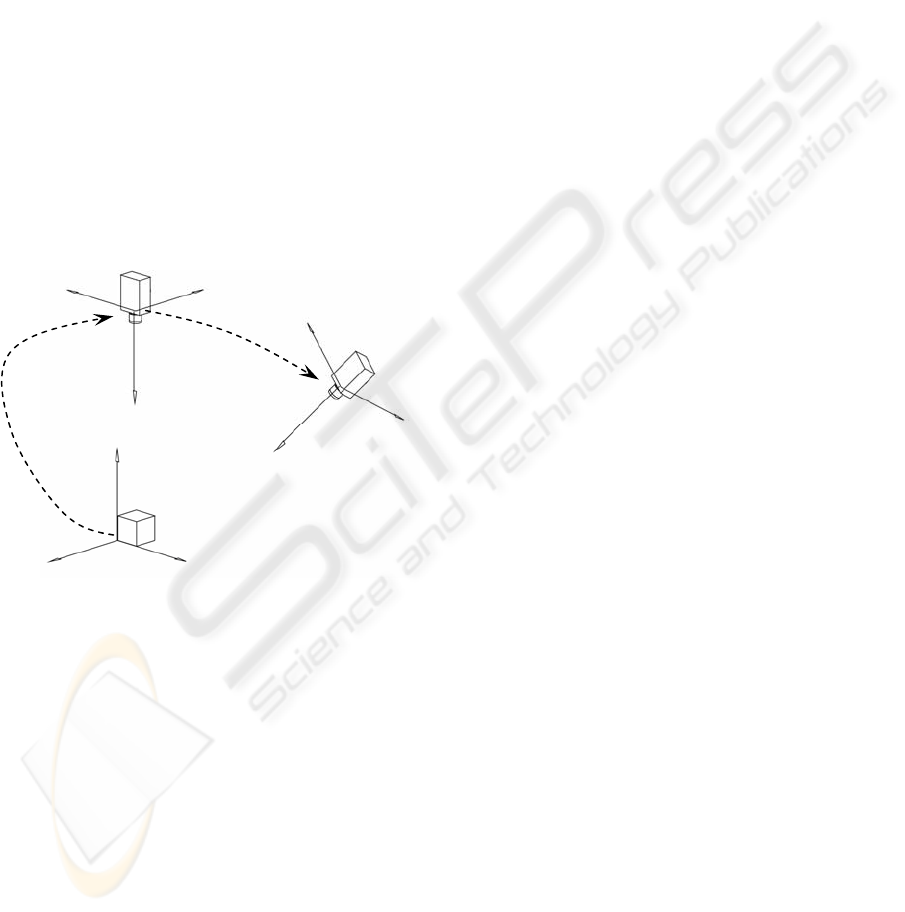
2 CAMERA MOTION AS RIGID
BODY
As starting point a camera moving in front of several
objects in a scene can be considered. The camera
and objects are modelled as rigid objects. Therefore,
each motion can be specified as the motion of one
point on the object in respect to another on the
camera, the reason being because the distance
between any two points which belong to the same
object does not change when this object is moved.
Consequently, it is not necessary to specify the
trajectory of every point on the object in respect to
the camera. So, the inertial central moment is the
only point we have to consider on the objects, and
the optical center is the only point we have to
consider on the camera.
Figure 1: Camera movement relative to world reference
frame W.
Thus, if are the coordinates of the
camera in the time i=0, and , the coordinates of
the same point on Camera in the time i>0, the
geometric transformation which is experimented by
camera, is given by:
0
C
C
i
C
i
CTCRRT ⋅→→
033
/:
(1)
If the camera motion is represented in relation to a
world reference frame W, and this one is considered
fixed, without movement, then the camera motion C
is defined by rotational and translational movements
which are relative to W in the Euclidean Space.
These Euclidean transformations are denoted by
and , respectively. So, any point which is
relative to W can be posed relative to C with this
equation.
C
W
R
C
W
t
C
W
CC
W
CC
W
W
tPRPTP +⋅=⋅=
(2)
where
C
denotes an Euclidean transformation
that represents rotation and translation movements
of W in relation to C, and
C
is the point relative to
C. To this end, the equation 2, is converted to
homogeneous representation, appending a ‘1’ to the
coordinates of
C
, that is . Thus
a matrix form is used to rewrite it since a linear form
is more suitable to operate.
M
T
P
P
()
4
1, RPP
T
CC
∈=
C
C
W
C
W
W
P
tR
P ⋅
⎥
⎥
⎦
⎤
⎢
⎢
⎣
⎡
=
10
(3)
3 A GEOMETRIC MODEL OF
IMAGE FORMATION
In this section, the mathematical model of the image
formation process is introduced (Hartley,
2000)(Gruen, 2001). The pinhole camera is chosen
as the ideal model to define computer vision
processes, and to specify the image formation
process, particularly. This process can be described
as a set of transformation of coordinates between the
camera frame and the world frame (Section 2) and
transformations of projection of 3-D object
coordinates relative to camera onto 2-D image
coordinates. The transformations which determine
the movement of a rigid body are defined in
Euclidean space, and the transformations which
determine the projection onto the image plane are
defined in the Projection space.
(
)
C
W
C
W
C
W
tR
(
)
The pinhole camera model assumes that each
3D-point on an object is projected onto a camera
sensor through a point called the optical center. The
origin of the reference frame C is at this optical
center and the coordinates of a 3D-point relative to
C are denoted by
(
)
ZYXP
C
. In addition, the
coordinates of the same point on the image plane
which is projected through the camera sensor
are
,,
(
)
yxp
I
, where the reference frame image is
called I. The origin of the reference frame I is the
principal point o which is the intersection point of
the optical axis with the image plane, and the
parameter f defines the distance of image plane from
the optical center.
,
With reference to the pinhole camera model, the
transformation between the reference frames C and I
can be represented in homogeneous coordinates and
matrices, as follows:
T ,=
111
,
+++
=
i
i
i
i
i
i
tRT
Z
Z
C
Z
C
X
C
X
C
Y
C
Y
C
C
i
C
i
+
1
W
X
W
Y
W
W
ICINCO 2007 - International Conference on Informatics in Control, Automation and Robotics
312

⎥
⎥
⎥
⎥
⎦
⎤
⎢
⎢
⎢
⎢
⎣
⎡
⋅
⎥
⎥
⎥
⎦
⎤
⎢
⎢
⎢
⎣
⎡
=
⎥
⎥
⎥
⎦
⎤
⎢
⎢
⎢
⎣
⎡
=
⎥
⎥
⎥
⎦
⎤
⎢
⎢
⎢
⎣
⎡
1
0100
000
000
1
Z
Y
X
f
f
Z
fY
fX
y
x
Z
(4)
where Z is the depth of the object and f is the focal
length.
If the equation is decomposed in two matrices,
K
f
y Π
0
, where the first matrix is called focal matrix,
and the second matrix is often referred to as
canonical projection matrix, the ideal model can be
described as
CfI
PKp ⋅
Π
⋅=
0
(5)
However, in practice, the projection
transformation between C and I, is very much
complex. The matrix K
f
depends on others
parameters as the size of the pixels, the form of the
pixels, etc. Therefore, a method to make the
geometric formation image more suitable, is needed.
The practice model has to consider (according to
(Ma, 2004)):
• The size of pixels. The reason is because
the size of the sensor is different to the size of
the image. Therefore, the scaling factors
must be considered. A point on image
plane in terms of mm is projected as
a point on image
),(
yx
ss
(
yxp
I
,
)
(
)
vup ,
in terms of pixels.
• The pixels are not square and do not have
orthogonal axis. Therefore, a factor called
skew, s
θ
,
can be used to define the angle
between the image axes.
• In addition, the origin of image plane does
not coincide with the intersection of the
optical axis and the image plane. There is a
translational movement between the geometric
center on image and the principal point. For
this reason the principal point is computed by
a calibration process (Zhang, 1999).
If the ideal projection model, pinhole model
camera, is modified with these parameters to adapt
it to the formation image process and a CCD
camera is used, the Equation 5 can be rewritten in
the following way:
CCfs
PKPKKp ⋅Π⋅=⋅Π⋅⋅=
00
(6)
where the triangular matrix, K=K
s
·K
f
, is known as
the calibration matrix or intrinsic parameters matrix
and its general form is:
⎥
⎥
⎥
⎦
⎤
⎢
⎢
⎢
⎣
⎡
=
100
0
yy
xx
ofs
ofsfs
K
θ
(7)
A calibrated camera with a checkboard pattern
has been used in this work. The values for K are:
f=21mm, s
x
=96.6pixels/mm, s
y
=89.3pixels/mm,
s
θ
=0, o
x
=331pixels y o
y
=240 pixels.
4 MINIMIZING OCCLUSIONS
The aim of the work presented in this paper is to
minimize the zones of occlusions of an object in a
scene in which several objects are present. This
object has part of its surface occluded by other
objects. A camera moving in front of the scene is
used to obtain a viewpoint that reduces the occlusion
zone of the object desired. Thus, the visibility of the
object partially occluded will be improved. This
means that more surface of the object desired can be
captured by camera.
In the time 0, the initial camera position is given
by . On the other hand where i >0 represents
the camera position at every moment of time. In
addition, the camera position which offers the best
viewpoint is represented by . This camera
position is the position which minimizes the
occlusion zone of the desired object, and which
maximizes its visible surface.
0
C
i
C
*i
C
In order to avoid modifying the intrinsic
parameters matrix of the camera, the space of
movements for the camera has been limited. Thus
the movement of the camera has been planned like a
point which is moved on a hemispheric surface. This
way the objects in the scene are located in the center
of the hemisphere and the camera can only be
located in positions which maintain the same
distance to the objects that shown by . Therefore,
the distance between camera and objects does not
change. This distance is determined by the ratio of
the hemisphere, r, which limits the space search of
the possible position for the camera. As a result, the
camera does not need to be recalibrated because it is
not necessary to obtain a new focal length. A study
about the suitable movement of a camera into
regions sphere is shown in (Wunsch, 1997).
i
C
0
C
Each camera position is determined by two
parameters: length and latitude. Each position,
(
)
ZYXP
C
,,
is defined by the displacements in
length relative to the initial position, , which is
determined by the angle
0
C
[]
π
θ
2,0∈
and by the
displacements in latitude which is determined by the
angle
[
]
2,0
π
ϕ
∈
. This way, it is possible to define
any possible position which can be adopted by the
ESTIMATION OF CAMERA 3D-POSITION TO MINIMIZE OCCLUSIONS
313
camera in the hemispheric search space. The greatest
number of positions that the camera can adopt is
defined by . This defines the
complete space of camera position. Displacements
of 1 degree for length and latitude have been
respectively taken.
2
..0/
π
=∀ iC
i
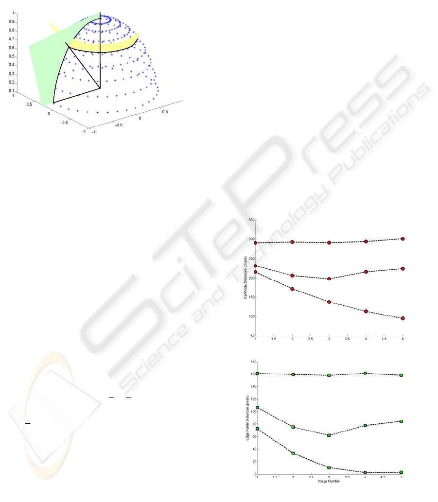
Figure 2: Space of movements for the camera.
The value for each iteration, determined by
length and latitude angles, can be modified to
increase or to reduce the search space of camera
positions. These parameters are chosen depending
on the velocity of computation for the analysis of
camera positions, and the precision to compute the
best camera position for a good viewpoint.
To obtain the best camera position, two
parameters have been evaluated: distances and areas.
If the zones of occlusion detected in the image must
be diminished, the objects in image space must be
separated as far as possible.
is
*i
C )}
1
,(max{/
+
k
o
k
odC
i
in image i
(8)
Therefore, the first evaluated parameter is the
distance between objects. The minimum distance
between two objects represented in image space, o
k
and o
k+1
is chosen as the minimum distance between
the points of each object. It is described as:
)}
1
,(min{)
1
,(
+
=
+
k
p
k
pd
k
o
k
od
(9)
where
),...,(
1 knk
pp
k
p =
p ∈=
is the vector of points
which represent the object o
k
in space image, and
where each point of object .
2
),( Rvu
ki
kiki
The distance is computed as the length of the
line segment between them. Two kinds of distance
are used: the distance between the centroid of
objects and the distance between the points of edges,
which represent the object boundaries. In three-
space, the distance does not change because the
objects are not in movement. Nevertheless, in image
space, the distance changes because the position of
an object in relation to another depends on the
viewpoint of the camera which is used to capture the
image. A comparison of both distance parameters is
shown in Figure 3. The distances computed among
edge points decreases and converge to zero when an
object occludes another. Although, if the distance is
computed from the centroids of the segmented
region, it can be unstable because when an object
occludes another, the first modifies the centroid of
the second. The second parameter is the area of each
object. This is the visible surface of each object. For
the study of the object areas, two cases can be
considered.
ϕ
θ
r
i
C
0
C
First case: The viewpoint of camera is not
changed and only the location of an object is
modified until another is occluded (the movement is
in the same orthogonal plane relative to the camera).
So, the visible surface of the object occluded has
been decreased and the rest of the objects maintain
the same area visible. This is shown in Figure 4.
Second case: The viewpoint of the camera is
changed and a new perspective is made in the image
captured by it. Thus, the area of each object is
changed (see Figure 5). But also, when several poses
of camera compute a measure of distance, this fact
indicates that occlusions are not present.
Centroids Distances
i-Image nu
m
b
er
Ed
g
e Points Distances
i-Ima
g
e number
Figure 3: Distances between objects evaluated for the
images shown in Figure 4.
ICINCO 2007 - International Conference on Informatics in Control, Automation and Robotics
314
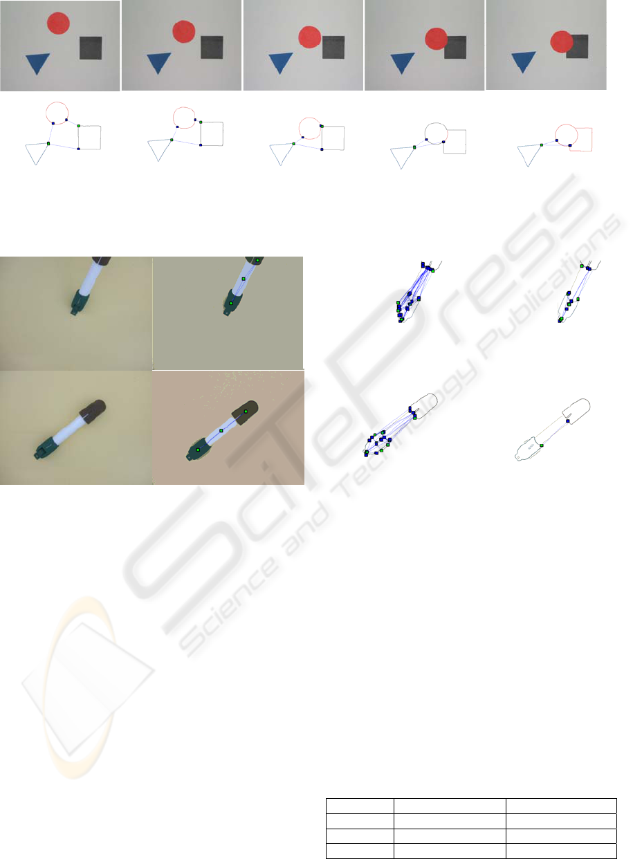
Figure 4: Distances computed among synthetic objects in real images. a) Image sequence with movement of an object.
b) Objects segmented from colour and edges, and distances computed from points of edges.
Figure 5: Distances computed among real objects in images. a) An assembly of several objects. b) Distance considering
center of gravity. c) Distance considering points of edges. d) Distance considering only optimized points of edges.
Thus, the measure of area of each object must be
evaluated and the best pose of camera is one in
which the perspective in the image maximizes the
sum of areas of each object.
Figure 5b shows the experimental results of
applying a colour segmentation process to obtain
object regions and, in this way, computing areas
(Gil, 2006). In addition, only the segmented regions
with a number of pixels major than 5% of pixels in
image are taken as objects except the background
which is the region with the major number of pixels.
For these regions, not only the centroids are
computed but also the distances between them. For
this experiment, the segmentation process detects 6
regions, however only 3 regions are marked as
objects from 3 automatic thresholds by each colour
component.
Figure 5c shows the edge segmentation process
of colour regions computed in Figure 5b and the
distance computed between points of edges belongs
to different objects. Finally, Figure 5d shows the
distance computed between objects when only
optimized edges are considered. The optimized
edges are the detected edges which have a number of
points major than the standard deviation. The
standard deviation determines the measure of
variability of the number points which determine an
edge from its mean. For this experiment, the
detected edges have been 9 and 13 respectively, and
the optimized edges 3 and 5 respectively. These
edges are approached by segments.
Table 1: Distances between objects computed from the
two real views shown in Figure 5 using centroids and
points of edge.
Objects View 1 View 2
d(1,2) 208,129 (129,448) 252,621 (145)
d(1,3) 112,397 (6,403) 123,465 (4,123)
d(2,3) 96,714 (14,422) 129,176 (9,055)
a
)
b)
b)
a)
c
)
d
)
ESTIMATION OF CAMERA 3D-POSITION TO MINIMIZE OCCLUSIONS
315
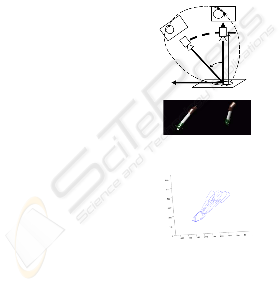
Table 1 shows how the distances computed from
centroids are increased if the camera makes the
movement shown in Figure 5. Nevertheless, the
distances computed from the points of edges can be
increased slowly if the real distance between objects
is closely near to zero. This fact is due to small
instabilities when two real images with different
perspective of a same scene are used to obtain
segments of boundary. Then, not always the same
points are detected in both images.
Although, this is not a problem because the
computed distances are always calculated from
edges back-projected in virtual images. Therefore,
the same points of edges appear in all the virtual
images, and only their positions in image are
changed.
5 POSE CAMERA TO MINIMIZE
OCCLUSION
RGB-colour images with size 640x480 have been
used in this work. The steps to explain this work are
detailed as follows.
In the first step, an initial image is captured from
the initial camera pose, . The 2D-points into
initial image are obtained from a colour and edges
segmentation process (Gil, 2006). An example of
this process has been shown in Figure 5. Next, the
distances between objects and its areas are computed
for this initial image. Afterwards, for this first
image, Equation 3 give the transformation between
world coordinates and camera coordinates to obtain
3D-points relative to . Also, the projective
matrix, Π, maps 3D-points, relative to , to image
points according to Equation 6. Given the
points in an image, a set of 3D-points in space that
map these points can be determined by means of
back-projection of 2D-points. That is:
i
C
i
C
i
C
(
vup ,
)
,
i
C
Wi
pTKpP
i
++
⋅Π⋅=Π= )(
0
ni ..1/ =
(10)
where n is number of position for the camera and the
pseudo-inverse of Π is the matrix Π
+
= Π
T
(ΠΠ
T
)
-1
which verify that ΠΠ
+
=I. Equation 10 can be
rewritten as a homography matrix, so that:
i
i
pHP
1−
=
(11)
When the 3D-points are known, the second step
consists of computing the projections of the 3D-
points which belong to objects from space of camera
poses (see Figure 2). This means that the 3D-poins
are mapped onto each virtual image for each camera
pose, as shown in Figure 6. Thus, virtual 2D-points
are computed. It is given by:
i
iii
i
pHHPHp
1
11
1
−
++
+
=⋅=
(12)
These virtual points determine the regions and edges
of objects in virtual images. Finally, the distances
between objects and areas of each object are
computed in each virtual image (Section 4).
Figure 6: a) Mapping points onto virtual images according
to camera movement. A displacement in length has been
mapped. b) CAD-Model of assembly used in Figure 5.
Figure 7: Back-projections onto virtual images from
camera movements.
Therefore, a set of
i
C
are evaluated as shown
in Figure 2. And the back-projection for each
i
C
is computed (see Figure 7). Concluding, the best
pose of the camera is determined by the
transformation which maximizes the distances and
the areas in the space of virtual images. This
transformation is given by the perspective matrix,
M
T
M
T
PHp
i
i
1
1
+
+
=
ii
pHP
1−
=
1+i
C
1+i
p
i
p
i
ii
i
pHHp )(
1
1
1
−
+
+
=
1+i
I
i
C
i
I
P
W
X
W
Z
r
θ
a
)
b)
ICINCO 2007 - International Conference on Informatics in Control, Automation and Robotics
316

and it determines what transformations
i
C
W
and
i
C
are more suitable. Afterwards, a robot PA-10
from Mitsubishi, with 7 degrees of freedom, moves
the camera mounted at its end to more suitable
computed pose.
R
W
t
6 CONCLUSIONS
The presented work provides an input to an object
recognition process. Thus, a method based on
extraction of characteristics in image, which is
based on the evaluation of the distances among these
characteristics, is used to determine when an
occlusion can appear. In addition, the method
evaluates the camera pose of a virtual way from the
back-projections of the characteristics detected in a
real image. The back-projections determine how the
characteristics are projected in virtual images
defined by different camera poses without the
necessity of camera is really moved. The
experimental results have shown that the proposed
estimation can successfully be used to determine the
camera pose that is not too sensitive to occlusions.
However, the approach proposed does not provide
an optimal solution. This could be solved by
applying visual control techniques which are
currently under investigation.
Our future work will extend this approach to
incorporate visual servoing in camera pose, allowing
for a robust positioning camera. A visual servoing
system with a configuration ‘eye-in-hand’ can be
used to evaluate each camera pose (Pomares, 2006).
Thus, the errors can be decreased and the trajectory
can be changed during the movement. In addition,
the information provided from a model CAD of the
objects (see Figure 6b) can be used to verify camera
poses in which it is located.
ACKNOWLEDGEMENTS
This work was funded by the Spanish MCYT project
“Diseño, implementación y experimentación de
escenarios de manipulación inteligentes para
aplicaciones de ensamblado y desensamblado
automático (DPI2005-
06222)”.
REFERENCES
Boshra, M., Ismail, M.A., 2000. Recognition of occluded
polyhedra from range images. Pattern Recognition.
Vol. 3, No. 8, 1351-1367.
Chan, C.J., Chen S.Y., 2002. Recognition Partially
Occluded Objects Using Markov Model. Int. J.
Pattern Recognition and Artificial Intelligence. Vol.
16, No. 2, 161-191.
El-Sonbaty, Y., Ismael, M.A, 2003. Matching Occluded
Objects Invariant to Rotations, Translations,
Reflections, and Scale Changes. Lecture Notes in
Computer Science. Vol. 2749, 836-843.
Fiala, M., 2005. Structure From Motion Using SIFT
Features and PH Transform with Panoramic Imagery.
Second Canadian Conference on Computer and Robot
Vision. Victoria, BC, Canada.
Gil, P., Torres, F., Ortiz, F.G., Reinoso, O., 2006.
Detection of partial occlusions of assembled
components to simplify the disassembly tasks.
International Journal of Advanced Manufacturing
Technology. No. 30, 530-539.
Gruen, A., Huang, T.S., 2001. Springer Series in
Information Sciences. Calibration and Orientation of
Cameras in Computer Vision. Springer-Verlag Berling
Heidelberg New York.
Hartley, R., Zisserman, A., 2000. Multiple View Geometry
in Computer Vision. Cambridge University Press.
Ma, Y., Soato S., Kosecka J., Shankar S., 2004. An
Invitation to 3-D Vision from Images to Geometric
Models. Springer-Verlag, New York Berlin
Heidelberg.
Ohba, K., Sato, Y., Ikeuchi, K., 2000. Appearance-based
visual learning and object recognition wirh
illumination invariance. Machine Vision and
Appplications 12, 189-196.
Ohayon, S., Rivlin, E., 2006. Robust 3D Head Tracking
Using Camera Pose Estimation. 18
th
International
Conference on Pattern Recognition. Hong Kong.
Park, B.G., Lee K.Y., Lee S.U., Lee J.H., 2003.
Recognition of partially occluded objects using
probabilistic ARG (attributed relational graph)-based
matching. Computer Vision and Image Understanding
90, 217-241.
Pomares, J., Gil, P., Garcia, G.J., Torres, F., 2006. Visual-
force control and structured Light fusion improve
object discontinuities recognition. 11
th
IEEE
International Conference on Emerging Technologies
and Factory Automation. Praga.
Silva, C., Victor, J.S., 2001. Motion from Occlusions.
Robotics and Autonomous Systems 35, 153-162.
Ying, Z., Castañon, D., 2000. Partially Occluded Object
Recognition Using Statical Models. Int. J. Computer
Vision. Vol. 49, No. 1, 57-78.
Wunsch, P., Winkler S., Hirzinger, G., 1997. Real-Time
Pose Estimation of 3-D Objects from Camera Images
Using Neural Networks. IEEE International
Conference on Robotics and Automation.Albuquerque,
New Mexico, USA.
Zhang, Z., 2000. A flexible new technique for camera
calibration. IEEE Transactions on Pattern Analysis
and Machine Intelligence, Vol 22. No. 11, 1330-1334.
ESTIMATION OF CAMERA 3D-POSITION TO MINIMIZE OCCLUSIONS
317
