
OPTICAL NAVIGATION SENSOR
Incorporating Vehicle Dynamics Information in Mapmaking
Tibor Takács and Viktor Kálmán
Department of Control Engineering and Information Technology, Budapest University of Technology and Economics
Magyar Tudósok körútja 2.,Budapest, Hungary
Keywords: Mobile robot navigation sensor, vehicle dynamics, map making.
Abstract: Accurate odometry and navigation may well be the most important tasks of a mobile robot’s control system.
To solve this task it is necessary to utilize proper sensors which provide reliable information about the
motion. This paper presents the prototype of an optical navigation sensor which can be an alternative choice
for the dead reckoning navigation system of a vehicle or mobile robot. The last part of the paper presents
another application in an inertial navigation system that enables a new approach to map making which
incorporates vehicle dynamics into the world map.
1 INTRODUCTION
Autonomous mobile robots gain more and more
importance in automotive, domestic and military
applications. Sensing and interpreting their
surroundings correctly are crucial in all these areas.
The sensor presented in this paper aims to improve
existing odometry methods, and to aid the creation
of world maps that incorporate the state of the
vehicle in the world map and classifies terrain
accordingly. In the first half of this document an
overview of the principle and the prototype of the
optical navigation sensor are presented, the second
section of the paper proposes a method for world
model building for mobile robots and shows some
other application where this sensor can be used.
2 NAVIGATION TECHNIQUES
Accurate self localization is one of the most
important topics in autonomous vehicle technology.
During centuries researchers have developed a lot of
techniques to measure the precise position of land or
aerial vehicles and mobile robots.
Global methods (e.g. GPS) determine directly the
ab
solute position, but unfortunately in several cases
these are not useable, due to reception problems.
Dead reckoning methods estimate the present
l
ocation of a navigating agent by advancing some
previous position using known course, velocity and
time information (Borenstein, 1996).
The odometry (the most simplistic and prevalent
i
mplementation of dead reckoning) estimates the
course and distance of the moving agent’s path to
calculate the global location by measuring the wheel
rotation and/or the steering orientation (Dixon,
1997). This position estimating can be strongly
inaccurate under real conditions through the
mobility configuration (e.g. tracked vehicles) or
through the wheel-slippage, overacceleration or
driving over uneven floor.
3 OPTICAL NAVIGATION SENSOR
3.1 Optical Flow
Through of the inaccuracy of the odometry it is
necessary to develop a cheap sensor-system that
provides well-authenticated dislocation-data for
dead reckoning navigation in real world conditions.
The optical navigation sensor is a possible solution
to fulfil these conditions.
The working principle of the sensor is optical
flow,
namely the motion information is generated
from visual information (from an image-sequence
provided by a camera facing the ground). Typically
the motion is represented as vectors originating or
271
Takács T. and Kálmán V. (2007).
OPTICAL NAVIGATION SENSOR - Incorporating Vehicle Dynamics Information in Mapmaking.
In Proceedings of the Fourth International Conference on Informatics in Control, Automation and Robotics, pages 271-274
DOI: 10.5220/0001648102710274
Copyright
c
SciTePress
terminating at pixels in a digital image sequence
(CVRG, 2000). An example is shown in figure 1.
Figure 1: The principle of the optical flow.
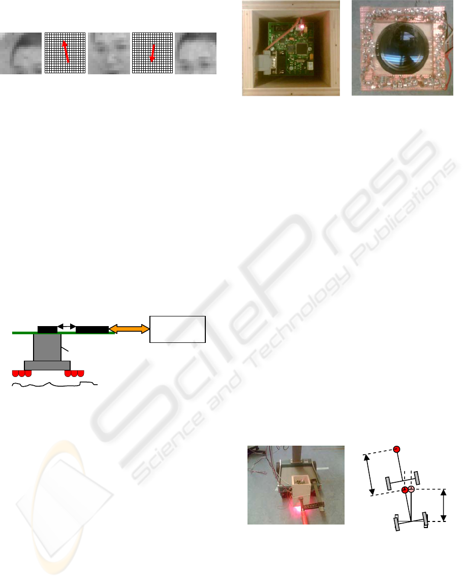
3.2 The Prototype of the Sensor
As a basis for further research, we have built the
prototype of the optical navigation sensor (see figure
2 and figure 3).
As a camera (what provides the image-sequence
for calculating the dislocation) we have chosen the
sensing and processing chip of a low-cost and wide-
spread optical mouse. (Hereinafter this chip is
referred to as “mouse-chip”.) The chip includes a
low-resolution camera and a DSP for calculating the
optical flow by hardware at a very high rate.
Although its resolution is relatively low, for motion
detection and measurement it is sufficient because
only the texture is important. It measures the relative
dislocations in the x and y direction.
Figure 2: The model of the sensor.
Because of the uneven floor the distance between
the sensor and the floor is continuously changing. To
compensate this effect the sensor has telecentric
optics, which has a constant magnification rate
therefore in a certain range the measurements are
independent from the height of the sensor relative to
the ground.
Naturally, it was necessary to design a
microcontroller based architecture round the mouse-
chip which offers a useable interface for a dead
reckoning navigation system. The microcontroller
reads the motion or the image information of the
mouse-chip and sends them to the processing unit,
for example to a PC in the development stage or to a
navigation or control unit at real conditions (Takács,
2007).
Figure 3: The prototype of the sensor.
3.3 Testing, Error Measurement
To measure the errors of the sensor we mounted it
on a test platform (figure 3/a) and performed some
experiments.
The first group of tests analyzes the dependence
from the texture of the floor and from the height
over ground. The experience showed that the sensor
is really insensitive to the height (thanks to the
telecentric optics) but unfortunately it sometimes
misses on shining or totally homogeneous surfaces.
This property is inherited from the mouse-chip of
the cheap optical mice. Laser equipped optical mice
might be better from this aspect. Therefore using the
mouse-chip of a laser mouse presumably solves this
problem.
With the second type of the tests we measured
the accuracy of the sensor. First we determined the
model of the platform then we executed the so called
unidirectional square-path test (Borenstein, 1996).
The model of the navigating agent and the
connection between the motion and the measured
sensor values is shown on figure 3/b. The y
component measures orientation change, the linear
dislocation appears in the value of the x component.
Figure 3: The test platform and its model.
By normal conditions the measured error was
relatively small in the course of movement around
the square. 4,5 meters of travel yielded 0,01-0,02
meters of the inaccuracy (meaning 0,3% overall
error).
Control
unit
LEDs
Telecentric Optics
Mouse-chi
p
Microcontrolle
r
a.) c.) b.) d.) e.)
From above From under
D
dy
dx
A
b.) a.)
ICINCO 2007 - International Conference on Informatics in Control, Automation and Robotics
272

It is important to add that slip free wheel contact
was supposed. In case of slippage the error grew
dramatically, the inaccuracy could even reach the
0,3-0,4 meters (7% error). It was caused by the
appearance of linear dislocation in the value of the y
component, and the ratio between the linear
dislocation and the orientation change can not been
determined.
It seems to be a paradox situation since this
optical navigation sensor was developed for
replacing the wheel encoder based odometry,
however we faced the same problem (the inaccuracy
from the slippage of the wheels). But as opposed to
the odometry, out experiences showed, that this
method has a simple and effective solution. By using
two optical sensors, a platform independent an
accurate dead reckoning navigating sensor-system
can be developed that works well under real
conditions (wheel-slippage, travel over uneven floor
etc.) too.
4 ALTERNATIVE APPLICATIONS
4.1 Electronic Stability Control of
Vehicles
One of the most critical areas of stability systems
(ESP, ABS etc.) is the accurate measurement of the
dynamic state of the vehicle. Probably the most
important state variable is the slip angle of the
moving vehicle. It is needed for the calculation of
the force between the wheels and the ground and
also for the exact description of the motion-state.
Presently used measurement procedures of the
slip angle are in general very expensive therefore it
they are not really usable in mass production
(Kálmán, 2005). Hence it is necessary to use
estimation methods to provide the value of the slip
angle. Unfortunately these procedures can not
provide accurate results (Bári, 2006).
This optical sensor provides an effective and
cheap solution to solve the problem of the slip angle
because it can measure (instead of estimation)
directly the slip angle, the ground velocity in 2D and
other important motion information. Therefore it can
be an additional sensor of any vehicle handling
enhancement system, for example ABS or ESP.
Naturally for utilization in the automotive industry it
is necessary to fulfil numerous standards and
reliability requirements, which will not be discussed
in this paper.
4.2 Linking Vehicle Dynamic Properties
into World Map Building
Another interesting area of application is a multi
sensor navigation unit of a mobile robot or
automated vehicle. By fusing information from the
optical correlation sensor and other sensors
measuring the vehicles inner state - such as
acceleration, tilt, wheel speed, GPS sensors - very
precise dynamical information can be obtained. This
information can be used to build a world map that
contains information not only about the environment
but also its effects on the dynamical behaviour of the
robotic vehicle. The optical sensor plays an
important role in this unit because it is able to
measure true ground velocity relative to our vehicle,
making us able to determine wheel slippage and slip
angle.
Intelligent mobile robots navigate around in their
environment by gathering information about their
surroundings. The most common approach is to use
ranging sensors mounted on the robot to form
occupancy grids or equivalent. Other approaches
avoid this metric division of space and favour
topological mapping. By combining these mapping
techniques it is possible to form a hierarchical map
that has the advantages of both methods while some
of the disadvantages can be avoided (Thrun, 1998).
Occupancy grids classify the individual cells
based on range data and possibly other features such
as colour or surface texture or variation. This
becomes very important in outdoor mobile robotics
when the robot needs to distinguish between real
obstacles and traversable terrain. An extreme case is
given by navigation in a field of tall grass. The
elevation map will represent the scene as a basically
horizontal surface above the ground level; that is, as
a big obstacle in front of the vehicle. It is apparent
that only by integrating the geometry description
with terrain cover characterization will a robot be
able to navigate in such critical conditions (Belluta,
2000).
Topological maps describe the world in terms of
connections between regions. This is usually enough
indoors, or in well structured environments, but
when travelling through more complex terrain a
different representation might be necessary. For
example a sloping gravel road or sand dune may
only be traversable at a certain speed or only one
way, up or downwards. By applying information
from the inertial navigational unit, such as slope
angle, wheel slippage, actual movement versus
desired movement, these characteristics can be
learned (or used from apriori information) and the
OPTICAL NAVIGATION SENSOR - Incorporating Vehicle Dynamics Information in Mapmaking
273

connections of the topological graph can be updated
accordingly.
Terrain characteristics (and those of our vehicle)
determine the maximum safe speed, braking distance
curve radius at a given speed, climbing manoeuvres
etc. It is obvious that the more information we have
about a certain region we are planning to travel
through, the more driving efficiency we can achieve,
as it is generally unsafe to drive at high speed
through bumpy terrain or make fast turns on a
slippery surface. By incorporating the data from the
navigational unit into the world map, we can
associate driving guidelines to a given map segment.
Also on the higher, topological level - using apriori
information - we can identify the type of the terrain
for a given point of our topological graph, as office
environment, forest, urban area, desert etc. By doing
so, we narrow down our choices when making
decisions about terrain coverage. For example it is
unlikely to encounter sand, water or foliage in an
office environment. If we know the type of terrain
ahead we can make a more accurate estimate of the
driveability of the area thus increasing driving
efficiency.
In this section a hierarchical map making method
was proposed which uses data from a multi-sensor
navigation unit that supplies information about
vehicle dynamics. This unit heavily relies on the
optical correlation sensor described in the preceding
sections. By measuring wheel slip and vehicle slip
angle we are able to associate drivability guidelines
such as safe speed, friction coefficient, minimal
driving speed etc. to a given map segment or type of
terrain. A higher level of environment recognition
was also proposed: based on apriori information, or
sensor data the vehicles control system decides the
type of environment (e.g. office, forest, desert) the
robot traverses at the time, and changes the
probability of terrain types, characteristic of the type
of environment, thus simplifying terrain
classification.
5 SUMMARY
In the previous sections we presented an optical
navigation sensor which measures motion
information (velocity, dislocation, slip angle)
without ground contact.
An alternative dead reckoning technique is
proposed in section
3, that yields superior accuracy
compared to wheel encoder based methods. In the
first part a short overview of principle (e.g. optical
flow) is given followed by the description of our
experimental setup. Experimental results are given
in the last part. Conclusions: the current system
should be made platform independent by using two
rigidly linked sensors, use of laser mouse chips is
recommended to overcome the problem of texture
dependency.
Finally examples of alternative application areas
were presented: slip angle measurement for the
safety systems of vehicles and hierarchical map
building with additional driveability information.
As a conclusion we can say that the device and
dependent methods presented here can serve as
cheap and accurate alternative solutions to numerous
problems of the robot and automotive industry.
REFERENCES
Borenstein, J., Everett, H. R., Feng, L., 1996. “Where am
I?” Sensors and Methods for Mobile Robot
Positioning, 13-29., 130-150.
Takács, T., 2007. Alternative Path-Tracking Sensor-
System for Mobile Robots, microCAD – International
Scientific Conference.
Bári, G., Kálmán V., Szabó, B., 2006. Járműdinamikai
állapotbecslő algoritmus fejlesztése. A jövő járműve –
Járműipari innováció, BME-EJJT, in Hungarian.
Kálmán, V., 2005. Elemzés az "optical flow"
(~képfolyam) elven működő jármű és mobil robot-
technikai érzékelők kínálatáról, in Hungarian.
Dixon, J., Henlich, O., 1997. Mobile Robot Navigation,
SURPISE. Retrieved from
http://www.doc.ic.ac.uk/~nd/surprise_97/journal/vol4/
jmd/
Horn, B.K.P., Schunck, B.G., 1980. Determining optical
flow. AI Memo 572. Massachusetts Institue of
Technology.
Thrun, S., 1998. Learning maps for indoor mobile robot
navigation. Artificial Intelligence, 99(1): 21–71..
Belluta, P., Manduchi, R., Matthies, L., Owens, K.,
Rankin, A., 2000. Terrain Perception for Demo III.
Proceedings of the Intelligent Vehicles Symposium.
Dearborn, Michigan.
ICINCO 2007 - International Conference on Informatics in Control, Automation and Robotics
274
