
A MULTIROBOT SYSTEM FOR DISTRIBUTED SENSING
Janne Haverinen, Anssi Kemppainen, Janne Kivijakola and Juha Röning
Department of Electrical and Information Engineering, University of Oulu, Finland
Keywords:
Multi-robot system, distributed sensing, laser, range sensing.
Abstract:
This paper presents a modular multirobot system developed for distributed sensing experiments. The mul-
tirobot system is composed of modular small size robots, which have various sensor capabilities including a
color stereo camera system and an infrared based sensor for infrastructure independent relative pose estimation
of robots. The paper describes the current state of the multirobot system introducing the robots, their sensor
capabilites, and some initial experiments conducted with the system. The experiments include a distributed
structured light based 3-D scanning experiment involving two robots, and an experiment where a group of
robots arrange into a spatial formation and measures distributions of light and magnetic field of an environ-
ment. The experiments demonstrate how the proposed multirobot system can be used to extract information
from the environment, and how they can cooperatively perform non trivial tasks, like 3-D scanning, which is
a difficult task for a single small size robot due to limitations of current sensing technologies. The distributed
3-D scanning method introduced in this paper demonstrates how multirobot system’s inherent properties, i.e.
spatial distribution and mobility, can be utilized in a novel way. The experiment demonstrates how distributed
measurement devices can be created, in which each robot has an unique role as a part of the device, and in
which the mobility of the robots provides flexibility to the structure of the measurement system.
1 INTRODUCTION
The miniaturization of mobile robots (Floreano and
Mondada, 1998; Caprari et al., 2000; Sibley et al.,
2002; Colot et al., 2004; Mondada et al., 2004) is
rapidly progressing due to developments in electron-
ics and material technology, for example. Multirobot
systems composed of a group of miniaturized robots
can have numerous applications in the future. They
may be a regular sight on space expeditions or they
may operate inside the human body for our well be-
ing. At present, multirobot systems are a rear sight
in real world applications. However, they have al-
ready been used in surveillance applications, military
demonstrations, and in distributed sensing applica-
tions. The distributed sensing is an interesting appli-
cation domain as the multirobot system is inherently
spatially distributed. As this paper shows, the spatial
distribution of robots can be naturally utilized to over-
come problems that the miniaturization of the robots
introduces to the sensing technology in some prob-
lem domains. As an example, we will show how a
multirobot system can be used as a distributed struc-
tured light based scanning device for extracting 3-D
information from an environment. The distributed 3-
D scanning concept is useful in applications where
a group of robots needs to extract objects’ geometri-
cal information in remote locations without a require-
ment that a single robot must carry alone the neces-
sary technology for performing the range measure-
ments (Lee and Song, 2005).
An other experiment, which demonstrates the fea-
sibility of the proposed multirobot system, shows
how robots can be driven into a given spatial for-
mation, and used to automatically perform measure-
ments about illumination and magnetic field of the en-
vironment.
This paper briefly introduces the developed mul-
tirobot system and its sensor capabilities. Then, two
experiments are briefly presented in order to demon-
137
Haver inen J., Kemppainen A., Kivijakola J. and Röning J. (2007).
A MULTIROBOT SYSTEM FOR DISTRIBUTED SENSING.
In Proceedings of the Fourth International Conference on Informatics in Control, Automation and Robotics, pages 137-142
DOI: 10.5220/0001649601370142
Copyright
c
SciTePress
strate how the system can be used in interesting real
world applications. The multirobot system is com-
posed of miniature mobile robots first introduced in
(Haverinen et al., 2005). Each robot can have vari-
ous sensor capabilities including a color stereo cam-
era system and an infrared based sensor for relative
pose estimation (Kemppainen et al., 2006). The ex-
periments are conducted by combining these sensor
capabilities (modules) to form both heterogeneous,
and homogeneous teams of robots.
2 THE MULTIROBOT SYSTEM
The presented multirobot system is composed of
modular miniature mobile robots (Haverinen et al.,
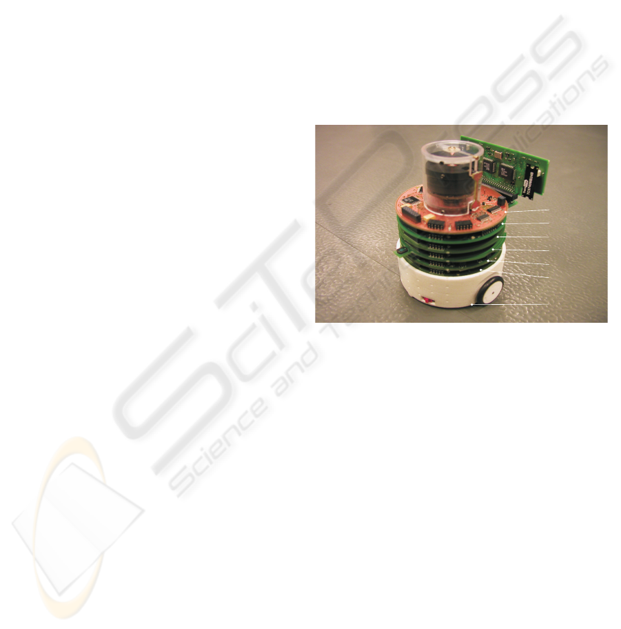
2005). One configuration of an individual robot is
shown in Fig. 1. In addition to DC-motor (actuator)
and power modules, the robot in Fig.1 has four other
modules, which are (from top): the IR-location, the
stereo camera, the radio, the environment, and the IR-
proximity modules, respectively. Each of these mod-
ules provide an well defined serial interface for read-
ing or writing data. All modules have an 8-bit low
power 8MHz MCU (ATmega32), which implements
the serial interface for accessing the module services,
and controls the logic of the module.
Each module can have from one to three different
serial interfaces (UART,I2C,SPI). While the UART
interface is mandatory for each module, I2C and SPI
interfaces are optional, and they are used for enhanc-
ing the bus performance. Each module with more
than one interface can be commanded to switch be-
tween interfaces in order to adapt the bus perfor-
mance.
The infrared based location module (Kemppainen
et al., 2006) is used to estimate the relative poses of
robots without external infrastructures such as bea-
cons, WLAN base stations, GPS or landmarks. The
operation principle of the location module is based on
omni directional amplitude modulated infrared trans-
mission and an infrared receiver that utilizes a rotating
beam collector for finding the direction of the infrared
transmission. The detected modulation frequency at
the receiver identifies the transmitting system. Each
location module has an unique transmission modu-
lation frequency, which gives identity for each robot
having the location unit.
By having the module, the robot can have esti-
mated poses of the surrounding robots within five me-
ters without any external infrastructure. The infrared
location module is utilized in the experiments where
robots must be driven into specific formations prior
distributed sensing procedure. The module can also
be utilized to maintain and adapt formations during a
task execution. The infrared location module is used
in all experiments described in this paper. In the 3-
D scanning experiment the location module provides
the necessary information to arrange the robots into
given line formation prior the scanning procedure. In
distributed sensing experiments, the module is used
to setup the initial measurement formation (see Fig.
6), and to maintain the formation during the measure-
ment procedure. Fig. 2 demonstrates how the location
module can be used to estimate the poses of the sur-
rounding robot. In Fig. 2 the robot at (0, 0) estimates
the poses of the two other robots for a short period of
time. Only the (x, y)-coordinates of the located robots
are shown (heading is not plotted). See (Kemppainen
et al., 2006) for more detailed description of the IR-
location module.
motor
IR-proximity
environment
radio
stereo camera
IR-location
power
Figure 1: One configuration of the miniature robot. This
robot has four modules in addition to motor and power mod-
ules. The modules include: the IR-location, the stereo cam-
era, the radio, the environment, and the IR-proximity mod-
ules. The environment module is used to measure acceler-
ations, temperature, ambient lighting, and the direction and
magnitude of the magnetic field. The radio module imple-
ments the 868MHz 100kbits radio link for inter robot and
PC communication. The purpose of the motor module is to
control the two DC-motors of the robot. The power module
is responsible of recharging the battery and providing the
power for all modules through the module bus.
3 EXPERIMENTS
The purpose of the presented experiments is to
demonstrate different strategies of using the multi-
robot system for distributed sensing. The first ex-
periment shows how a pair of heterogeneous robots
can be used as unique parts of a distributed measure-
ment device, and how system’s inherent mobility can
be utilized to provide a measurement device that has
the necessary flexibility of adapting measurement ge-
ometry to the structure of the environment. The sec-
ICINCO 2007 - International Conference on Informatics in Control, Automation and Robotics
138

Figure 2: The infrared location system provides the pose
estimates for two robots. The robot at (0, 0) is locating the
two other robots for a short period of time.
ond experiment shows how a team of homogeneous
robots can create a map of environment by moving in
a given formation and by making point measurements
about ambient lighting and magnetic field from loca-
tions found by dedicated infrared location modules.
3.1 Distributed 3-d Scanning
The setup of this experiment consist of two heteroge-
neous robots: one of the robots acts as a laser sheet
projector, and the other as a laser stripe detector. The
projector robot, shown in Fig. 3, has a special laser
module which includes 1mW (class I) laser stripe pro-
jector. The projector provides a vertical sheet of light
that is projected into the environment. The robot that
is acting as a laser stripe detector uses one of the color
CMOS cameras of the stereo camera module loaded
with a program that extracts the projected laser pat-
terns from the surfaces of objects in the camera’s field
of view.
The measurement geometry is depicted in Fig. 4.
First, the projector and the detector robots are aligned
into a given line formation in which the laser and the
camera are pointing to the left in regard to the driv-
ing direction. Both robots have now the same head-
ing. In order to have absolute range measurements the
parameters of the measurement geometry has to be
known (Haverinen and Röning, 2000). However, rel-
ative range measurements can be made without know-
ing the exact mutual poses of the two robots. In
our experiments, we have used both machine vision
technique (Heikkilä and Silven, 1997) and the loca-
tion module (Kemppainen et al., 2006) to arrange the
robots into the known initial measurement formation.
The machine vision technique utilizes the know land-
mark pattern mounted on the laser robot (shown in
Fig. 3) in order to estimate the mutual poses of the
robots.
The measurement geometry described in Fig. 4 is
not the only option. The robots can also be arranged
onto a circumference with both optical axis and the
laser sheet pointing to the center of the circle. By
driving along the the circumference with equal veloc-
ities the robots can perform a full scan of an object
that resides inside the circle. Yet another option is
to keep the robots on fixed locations and rotating the
projector robot: in this way the robots can scan a large
area from fixed locations. However, the angular mo-
tion of the projector robot must be known in order to
compute the range image.
In our experiments the scanning procedure starts
after the robots are properly aligned. Both robots are
moving with equal velocities. The camera robot per-
forms the image processing in order to extract the pro-
jected laser patterns reflected from the surfaces of ob-
jects. The image coordinates of the laser stripe on the
image plane are locally saved into the camera mod-
ule’s SDRAM. At the end of scanning, the image data
is transferred through the radio link to the host com-
puter (PC), which computes the final range image.
Fig. 5 shows examples of range images acquired
by the cooperating robots. The images demonstrate
how cooperating miniature robots can perform a de-
manding measurement task by acting as distributed
parts of the physical measurement device. The co-
operative scanning can have important applications:
a pair of miniature mobile robots can perform a re-
mote 3-D scanning procedure and acquire range data
from selected objects in environments that might be
unreachable by traditional 3-D measurement devices.
The range data gives important information about an
(possible hazardous) environment, objects, and their
geometrical properties. The presented distributed
sensing technique can provide dense range data for
creating 3-D maps of unknown environments with-
out computationally intensive stereo image process-
ing (Rocha et al., 2005), for example. The technique
can also be an alternative for creating data for vision
based 3-D SLAM (Tomono, 2005).
3.2 Cooperative Measurement of
Spatial Data
This experiment demonstrates how heterogeneous
robots can be used to perform a simple distributed
sensing task, and to create a spatial map of point mea-
surements. The experiment also highlights the fea-
sibility of the infrared location module in applica-
tions domains where locations of the robots must be
known. The infrared location system is used to cre-
ate and maintain the measurement formation, while
the robots are making point measurements with the
A MULTIROBOT SYSTEM FOR DISTRIBUTED SENSING
139

Figure 3: The laser robot. The robot consist of the 1mW
laser line projector. This robot also has a landmark pattern
which can be used to estimate the pose of the projector robot
in the detector robot’s coordinate system using the calibrate
camera module and defining its extrinsic parameters in re-
gard to the known landmark pattern (Heikkilä and Silven,
1997). Another technique to estimate the pose is to utilize
the IR-location module.
d
a
imageplane
lasersheet
object
camera’sfieldofview
v v
Figure 4: The measurement geometry used in the coopera-
tive scanning experiment. The robots are first aligned into a
line formation - both robots having the same heading. The
distance d and the angle α control the measurement reso-
lution and the measurement range. d and α can be adapted
on the basis of the measurement task. During the scanning
procedure, both robots maintain the same velocity v.
scalar sensors of the environment module. The mea-
surements are stored into a grid map with predefined
cell size. The value of each cell is the mean value
of the point measurements made in the corresponding
cell.
Although the experiment is simple, it has impor-
tant applications as it makes possible to automatically
gather spatial scalar data from the area of interest. The
data can then be used to analyze the lighting proper-
a)
20 40 60 80 100
50
100
150
200
b)
20 40 60 80 100 120 140 160 180 200
50
100
150
200
c)
20 40 60 80 100 120 140 160 180 200
50
100
150
200
Figure 5: Range images from three cooperative 3-D scan-
ning experiments. a) range image from arbitrary artificial
objects (a head statue and some polyhedrons). b) and c)
robots have scanned a person laying on the floor. These
images demonstrate how, by simple cooperation, a pair of
miniature mobile robots can obtain dense range data from
objects of an environment.
ties of the environment or to visualize how the mag-
netic field of the environment behaves due to metallic
structures in the environment, and analyze its proper-
ties over time, for example.
Fig. 6 shows the initial arrangement of the robots
prior the experiment (left): from these locations the
robots are driven into the measurement formation us-
ing the infrared location module (right). While main-
taining the measurement formation, the robots start
moving and doing measurements. The lighting mea-
ICINCO 2007 - International Conference on Informatics in Control, Automation and Robotics
140

surements are shown in Fig. 7, and the direction of
the magnetic field in each cell in presented in Fig. 8.
The Fig. 8 shows how the direction of the magnetic
field varies in the environment due to metallic objects
and structures. If this magnetic fingerprint of the en-
vironment is static it can be used to classify environ-
ments based on previous observations of the field on
the same area, for example.
Figure 6: Left: the initial (arbitrary) positions of the robots.
From initial poses the robots are driven into the measure-
ment formation by using the IR location module. Right:
The IR-location system has been utilized to drive the robots
into the given measurement formation. The robot in the
middle acts as a leader and the other two robots as follow-
ers.
−500 −400 −300 −200 −100 0 100 200 300 400 500
−400
−300
−200
−100
0
100
200
300
400
500
x [cm]
intensity
y [cm]
10
20
30
40
50
60
70
80
90
100
110
Figure 7: Measured ambient light intensities. The figure
shows the value, given by the ambient light sensor, for each
cell of the grid.
4 CONCLUSION
This paper presented a multirobot system developed
for distributed sensing experiments and applications.
Each robot has variety of sensors for measuring prop-
erties of an environment. The sensors include a tem-
perature sensor, an ambient light detector, a compass
module, accelerometers, and a color stereo camera
system.
Distributed measurement tasks are naturally
suited for multirobot system as they are inherently
−400 −300 −200 −100 0 100 200 300 400 500
−400
−300
−200
−100
0
100
200
300
400
500
x [cm]
y [cm]
heading
Figure 8: Measured directions of the magnetic field. The
figure shows how magnetic field varies due to metallic
structures of the environment. The variation (assuming it
being static over time) can be used to classify environments
based on previous observations from the same environment.
spatially distributed. The 3-D scanning experiment
showed how a pair of heterogeneous robots can coop-
erate by acting as parts of a distributed 3-D scanning
device. This observation is particularly important, as
this kind of measurement instrument is otherwise very
difficult to implement for a single miniature mobile
robot. The scanning experiment also demonstrated
how the multirobot system’s spatial distribution and
mobility can be utilized in a novel way to create dis-
tributed measurement devices in which each robot has
an role as a part of the device, and in which the mo-
bility of the robots provides flexibility to the structure
of the measurement system.
The aim of this research is to develop multirobot
systems which help humans to have meaningful infor-
mation from (remote) environments and its objects.
This information is then used to analyze the state of
the environment or to execute multirobot tasks au-
tonomously.
Based on the presented experiments, our purpose
is to go toward more demanding implementations
on which a person can instruct a multirobot system
to measure selected objects of the environment af-
ter which the robots take their positions and cooper-
atively gather information, like range data, about the
objects.
ACKNOWLEDGEMENTS
The authors gratefully acknowledge the support of the
Academy of Finland.
A MULTIROBOT SYSTEM FOR DISTRIBUTED SENSING
141

REFERENCES
Caprari, G., Arras, K., and Siegwart, R. (2000). The au-
tonomous miniature robot alice: from prototypes to
applications. In IEEE/RSJ International Conference
on Intelligent Robots and Systems (IROS’00), pages
793–798.
Colot, A., Caprari, G., and Siegwart, R. (2004). Insbot: De-
sign of an autonomous mini mobile robot able to inter-
act with cockroaches. In IEEE International Confer-
ence on Robotics and Automation (ICRA’2004), pages
2418–2423, New Orleans.
Floreano, D. and Mondada, F. (1998). Hardware solutions
for evolutionary robotics. In Husbands, P. and Meyer,
J.-A., editors, First European Workshop on Evolu-
tionary Robotics (EVOROBOT’1998, pages 137–151,
Berlin. Springer-Verlag.
Haverinen, J., Parpala, M., and Röning, J. (2005). A minia-
ture mobile robot with a color stereo camera system
for swarm robotics research. In IEEE International
Conference on Robotics and Automation (ICRA2005),
pages 2494–2497, Barcelona, Spain.
Haverinen, J. and Röning, J. (2000). A 3-d scanner
capturing range and color for the robotics applica-
tions. In 24th Workshop of the AAPR - Applications
of 3D-Imaging and Graph-based Modeling, Villach,
Carinthia, Austria.
Heikkilä, J. and Silven, O. (1997). A four-step camera
calibration procedure with implicit image correction.
In IEEE Conference on Computer Vision and Pat-
tern Recognition, pages 1106–1112, San Juan, Puerto
Rico.
Kemppainen, A., Haverinen, J., and Röning, J. (2006). An
infrared location system for realtive pose estimation
of robots. In 16-th CISM-IFToMM Syposium of Robot
Design, Dynamics, and Control (ROMANSY 2006),
Warsaw, Poland.
Lee, S. and Song, J.-B. (2005). Mobile robot localization
using range sensors: consecutive scanning and coop-
erative scanning. International Journal of Control,
Automation, and Systems, 3(1):1–14.
Mondada, F., Pattinaro, G., Guignard, A., Kwee, A., Flo-
reano, D., Deneubourg, J.-L., Nolfi, S., Gambardella,
L., and Dorigo, M. (2004). Swarm-bot: a new dis-
tributed robotic concept. Autonomous Robots, special
Issue on Swarm Robotics, 17(2-3):193–221.
Rocha, R., Dias, J., and Carvalho, A. (2005). Coopera-
tive multi-robot systems: A study of vision-based 3-d
mapping using information theory. In IEEE Interna-
tional Conference on Robotics and Automation, pages
386–391, Barcelone, Spain.
Sibley, G., Rahimi, M., and Sukhatme, G. (2002). Robo-
mote: A tiny mobile robot platform for large-scale
ad-hoc sensor networks. In IEEE International Con-
ference on Robotics and Automation (ICRA’2002),
Washington DC.
Tomono, M. (2005). 3-d localization and mapping using
a single camera based on structure-from-motion with
automatic baseline selection. In IEEE International
Conference on Robotics and Automation, pages 3353–
3358, Barcelone, Spain.
ICINCO 2007 - International Conference on Informatics in Control, Automation and Robotics
142
