
A HUMAN AIDED LEARNING PROCESS FOR AN ARTIFICIAL
IMMUNE SYSTEM BASED ROBOT CONTROL
An Implementation on an Autonomous Mobile Robot
Jan Illerhues and Nils Goerke
Division of Neural Computation, Department of Computer Science
University of Bonn, Bonn, Germany
Keywords:
Autonomous robot, systemic architecture, learning, artificial immune system, rule-like association (RLA).
Abstract:
In this paper we introduce a pre-structured learning process that enables a teacher to implement a robot con-
troller easily. The controller maps sensory data of a real, autonomous robot to motor values. The kind of
mapping is defined by a teacher. The learning process is divided into four phases and leads the agent from a
two stage supervised learning system via reinforcement learning to unsupervised autonomous learning. In the
beginning, the controller starts completely without knowledge and learns the new behaviours presented from
the teacher. In second phase is dedicated to improve the results from phase one. In the third phase of the learn-
ing process the teacher gives an evaluation of the states zhat the robot has reached performing the behaviours
taught in phase one and two. In the fourth phase the robot gains experience by evaluating the transitions of
the different behavioral states. The result of learning is stored in a rule-like association system (RLA), which
is inspired from the artificial immune system approach. The experience gained throughout the whole learning
process serves as knowledge base for planning actions to complete a task given by the teacher. This paper
presents the learning process, its implementation, and first results.
1 INTRODUCTION
Nowadays the development of a robot control is
mostly reserved for professionals. To integrate robots
into peoples’ everyday lives, it would be necessary to
give the user direct access to the robot’s behaviours. A
learning process would therefore be helpful, in which
the user acts as a teacher, showing the robot how to
act according to a special behaviour, without any pro-
gramming skills. By repeating this learning process,
the robot would gain more and more experience, en-
abling it to learn different behaviours. If the repertoire
of behaviours is large enough, the robot would be-
come capable of using its past experiences to choose
the best behaviour to fulfill a given task.
In this paper we introduce the implementation and
first results of such a learning process on a real robot.
The presented implementation is based on rule-like
associations (RLA) (Hart et al., 2003), as derived
from an artificial immune system approach. During
the learning process, a system of RLAs is created as
a knowledge-base, storing the learned results. This
knowledge base is used to choose robot actions when
faced with previously learned situations. The robot
is trained in real time, on-line. The teacher is pro-
viding training input while the robot is performing
actions. To give a maximal flexibility and mobility
during training, the interface between the teacher is
implemented as a PDA with wireless connection to
the moving robot. The learning process is divided
into four phases, which influence the RLA system fol-
lowing different learning paradigms: supervised, re-
inforcement, unsupervised. The presented implemen-
tation extends and accelerates an approach (Ratten-
berger et al., 2004), which provides an unsupervised
learning RLA system without planning and task ful-
filling skills.
2 THE COMPLETE SYSTEM
The learning program was implemented on the au-
tonomous, mobile robot ”KURT2” (KTO, 1995). A
sensory upstream prepares the sensory data of the
347
Illerhues J. and Goerke N. (2007).
A HUMAN AIDED LEARNING PROCESS FOR AN ARTIFICIAL IMMUNE SYSTEM BASED ROBOT CONTROL - An Implementation on an Autonomous
Mobile Robot.
In Proceedings of the Fourth International Conference on Informatics in Control, Automation and Robotics, pages 347-354
DOI: 10.5220/0001652303470354
Copyright
c
SciTePress
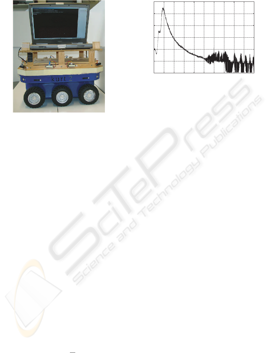
Figure 1: The robot ”KURT2”.
robot for the learnable robot controller. A motor
downstream converts the controller output to mo-
tor values, which could be directly addressed to the
robot. Both data streams match the requirements of
the Systemic Architecture (Goerke, 2001). The learn-
ing controller is responsible for the scheduling of the
teacher’s/robot’s communication, the management of
the knowledge-base (RLAs), the mapping of sensory
data to motor values and for choosing the right be-
haviour to fulfill a task.
2.1 The Agent
The robot ”Kurt2” (see figure 1) is an autonomous,
mobile agent. A notebook is fixed onto the robot’s
chassis, running the robot’s control software which
has a direct CAN-Bus connection to the robot.
The agent has a row with six supersonic sensors
and eight infrared sensors 14 cm above ground. A
nother row of 10 infrared sensors is installed 20 cm
above ground. The supersonic sensors are able to de-
tect objects nearly parallel to the robot’s chassis from
a distance of 10 cm to 70 cm. The values of the in-
frared sensors range from 0 to 550. They represent
distances from 10 cm (value 550) to 80 cm (value 0),
but may be very noisy. The mapping of the sensor
values to the distance of the object is non-linear (see
figure 2).
There are three wheels on each side of the robot
which are hard connected, thus doing exactly the
same; each side is controlled by one motor. Thes two
motors are able to move the robot forward and back-
ward, with speeds of up to 0.9
m
sec
in either direction.
Setting the motor speed of each side individually en-
ables the robot to not only drive straight ahead, but
also to make curves, u-turns and up to 360
◦
rotations.
0
100
200
300
400
500
600
0
10 20 30 40 50 60 70 80 90 100
Sensor value
Distance in cm
Figure 2: Mapping of distance to infrared sensor values.
2.2 The Rule-Like Association System
(RLA-System)
A rule-like association (Hart et al., 2003)(Webb et al.,
2003) maps a situation (presented by sensor values)
to motor values. Accordingly each RLA consists of
three sections: The first section C contains a (par-
tial) sensory description of a situation (condition C).
The second section is a robot action command A. The
third section of the used RLA-implementation con-
tains a description of the expected result E after ac-
tion A was performed in the situation described by
C. Therefore, a RLA describes a transition of states.
The RLA X whose condition part C describes the cur-
rent state of the robot the best, is chosen to control
the robot. Its corresponding action A is then used to
command the robot in its current state. After that, the
robot is in a new situation, and once again the RLA
with the closest matching C condition is chosen to
control the robot next. In this way the RLA controller
performs a reactive behaviour (Arkins, 1998).
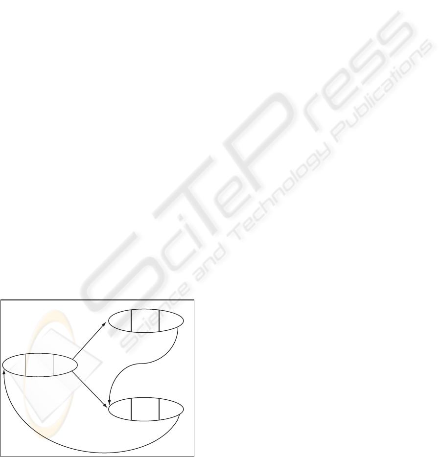
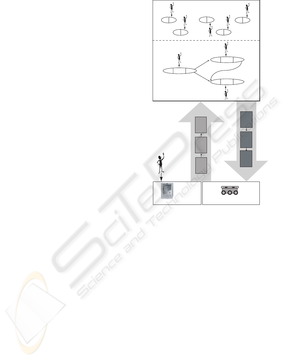
Taking this concept one step further, a network of
RLAs could be created (Ross, 2003). Thus making
it possible to store relations between different RLAs.
We built a RLA network in which each RLA is rep-
resented by a different node. An edge in the network
represents a successive relation: If RLA Y is chosen
after a RLA X was chosen, the network creates an
edge from node X to node Y. In that way the RLA
network is built (see figure 3).
2.3 The User Interface
A PDA is used as interface between the robot and the
teacher. The PDA communicates with the notebook
installed on the robot ”KURT2” per WLAN. W ith
this interface the user may send different information
to the robot:
• motor commands
ICINCO 2007 - International Conference on Informatics in Control, Automation and Robotics
348
The user may send the robot direct motor com-
mands.
• behaviours
The user can choose the behaviour that the robot
should perform.
• reinforcements
The user may give the robot reinforcements to
help evaluate situations or actions.
• organising commands
These are commands that organise learning, e.g.
cause an output of the RLA structure into a file.
2.4 Systemic Architecture
The Systemic Architecture contains the sensory up-
stream and the motor downstream.
The upstream collects the actual sensory data from
the robot as a vector of all sensor values and user
inputs. Afterwards, it performs a preprocessing of
the sensory values. The sensory values from the ul-
trasonic sensors have shown to be not reliable, be-
cause the beam of these ultrasonic sensors might be
reflected in an unintended way. Therefore we have
only used the infrared sensor values.
The front-side of the robot is resolved with five
sensors. On the left side of the robot however, we use
only two sensors. The difference of these two sensor
values is used to detect the position to a wall (turned
towards, turned away, or parallel). Additionally, we
use their maximum value to identify if any object is
detected on the left side. Thus from this information
we gain two virtual sensor values: one for positioning
purposes, and the other for object detection. The right
side is resolved the same way.
C
A
E
x
x
x
C
A
E
y
y
y
C
A
E
z
z
z
Figure 3: Example of a RLA system with 3 RLAs. Choos-
ing RLA X and performing its action A
x
could lead to the
situation described in C
y
, or to the situation described in
C
z
. Choosing RLA Y leads to the situation C
z
. RLA Z is
antecessor of RLA X.
The maximum of the backwards sensors is used
to receive object detection on the back side. All in
all we gain a vector of 10 (virtual) sensor values. We
receive further virtual sensor values by logging a his-
tory, which contains the average of the last five values
of each of these 10 sensors. These are added to the
sensor stream, and as a result we obtain a 20 dimen-
sional vector.
The values of this 20 dimensional vector are dis-
cretised in the following way: The front sensors and
their history values are translated into five discrete
values: 0 for ”Out-Of-Sight” (distance > 70 cm), 1
for ”Far Away” (70 cm ≥ distance > 40 cm), 2 for
”Middle-distance” (40 cm ≥ distance > 20 cm), 3 for
”Close” (20 cm ≥ distance > 12 cm) and 4 for ”Emer-
gency” (12 cm ≤ distance).
The values from the virtual sensor describing the
positioning are discretised as follows: 0 for ”Hard to-
wards the wall”, 1 for ”Slightly towards the wall”, 2
for ”Parallel to the wall”, 3 for ”Slightly away from
the wall” and 4 for ”Hard away from the wall”.
The object detection is binary coded with ”0” for
no object, and ”1” for an object detected.
Using this vector to describe a situation we
receive a state space with (5
5
· 5
2
· 2
3
)
2
· N =
390.625.000.000· N states, where N is the amount of
behaviours.
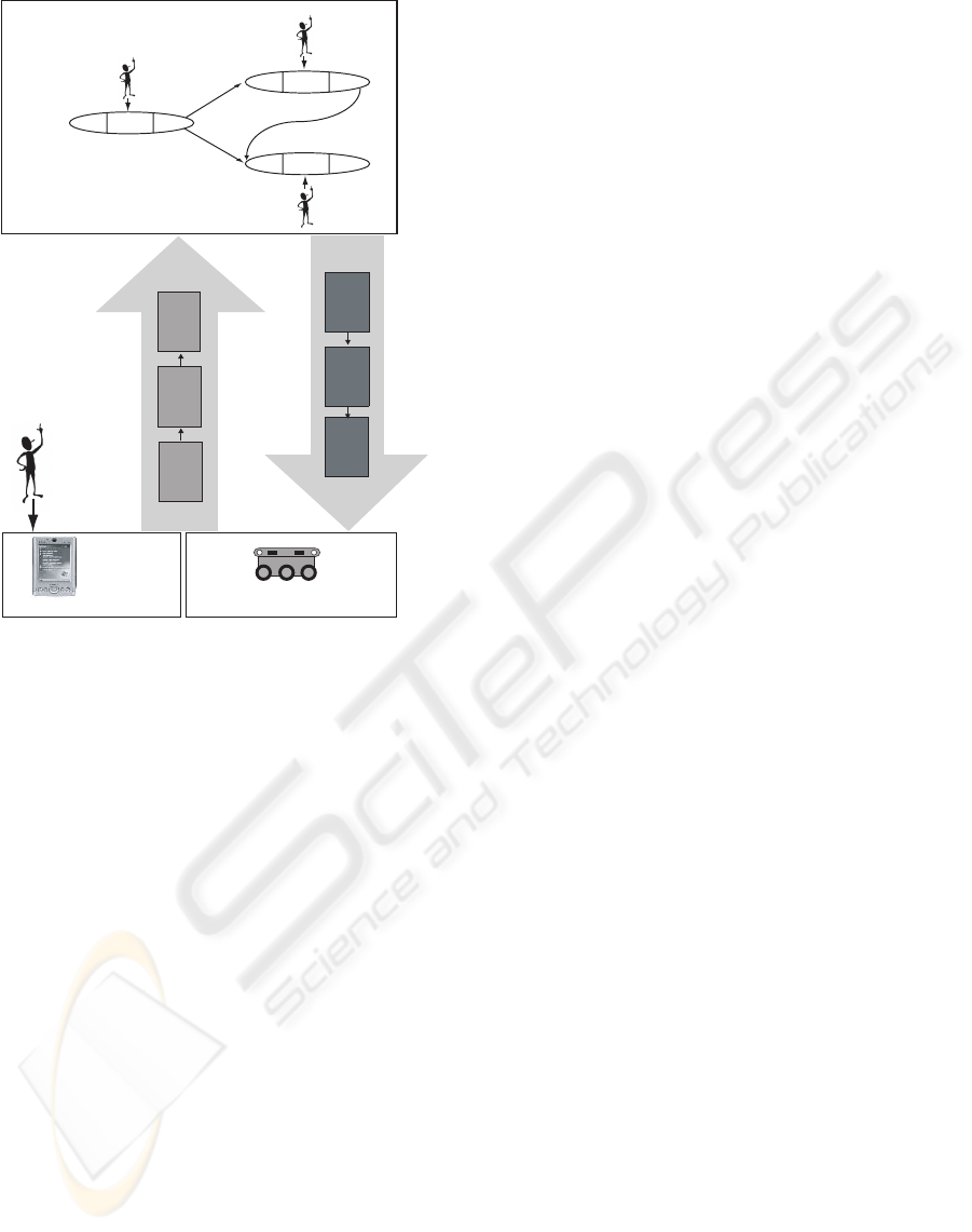
The upstream also analyses the user input. Each
behaviour has a characteristic number, which extends
the 20 dimensional vector by one component. The
resulting 21 dimensional vector serves as input to the
RLA system in the controller. All other user inputs
are forwarded directly to the controller (see figure 5
and 6).
3 PHASE 1- BASIC TRAINING
In this section the robot learns the basic movements
of a behaviour B by reactively planning its action. In
section 2.2 we described a RLA system, and the way
it could help the robot plan its action. The robot learns
a new behaviour B by creating new RLAs associated
with this behaviour. These RLAs describe situations
reached by performing the appropriate actions. At the
beginning the robot is completely unaware of this be-
haviour, because it has no RLAs and therefore all sit-
uations are unknown.
In this phase of the implementation, our aim is to
create adequate RLAs for the behaviour B. For each
new RLA we have to generate a situation-describing
condition part C, an action command A, and an ex-
pectation E. The controller works round-based, com-
paring the current situation of the robot with the con-
A HUMAN AIDED LEARNING PROCESS FOR AN ARTIFICIAL IMMUNE SYSTEM BASED ROBOT CONTROL -
An Implementation on an Autonomous Mobile Robot
349
dition C of each RLA. If a RLA was found that de-
scribes the situation adequately, its action A controls
the robot. If none is found, the scheme creates a new
RLA that matching the current situation C, and per-
forming its (new) action command A.
3.1 Find an Adequate RLA
In section 2.4 we introduced a vector which is used to
represent the robot’s current situation and current be-
haviour. To aid in the comparison between the C parts
of the RLAs and the current situation, the description
in part C is created in the same form as the input for
the current situation: a 21 dimensional vector, K.
It is now possible to measure the similarity be-
tween the current situation S and the C part of a
RLA containing vector K. This is done by building
the difference s
i
− k
i
between each i components of
both vectors. The more different the vectors are, the
more penalty points P the corresponding RLA gets.
Great differences should be rated worse than small
differences. Therefore we use the quadric difference
(s
i
− k
i
)
2
to calculate the penalty points. In respect to
this, penalty points P of the RLA ID are calculated as
follows:
P
ID
=
20
∑
i=0
(s
i
− k
i
)
2
The RLA with the smallest P value is therefore
the RLA with the best description of the current sit-
uation, and could be used to control the robot. If the
penalty points of this RLA are too high however, its
description of the current situation is not satisfactory.
To implement this we define a similarity radius. If
the penalty points are within the similarity radius, the
”winning” RLA could be used to control the robot. If
the minimum of the penalty points is outside of the
similarity radius, the current situation is declared as
unknown, the motors are stopped, and the controller
needs to create a new RLA.
For some behaviours, the importance of different
sensor-types may vary. For example, the front sen-
sors are very important for a collision avoidance be-
haviour, if the main moving direction is forward. In
this case the position to the wall is not important. In
contrast, the positioning sensors are necessary when
performing a ”wall-following”. To account for these
differences, we define an attention focus D. This vari-
able D is a 21 dimensional vector of integer numbers.
The higher the number d
i
, the more attention the cor-
responding sensor value s
i
gets. With respect to the
attention focus, the penalty points are calculated as
follows:
P
ID
=
20
∑
i=0
d
i
· (s
i
− k
i
)
2
0
10
20
30
40
50
60
70
80
90
0 100 200 300 400 500 600 700 800
Number of created RLAs
learning time [sec]
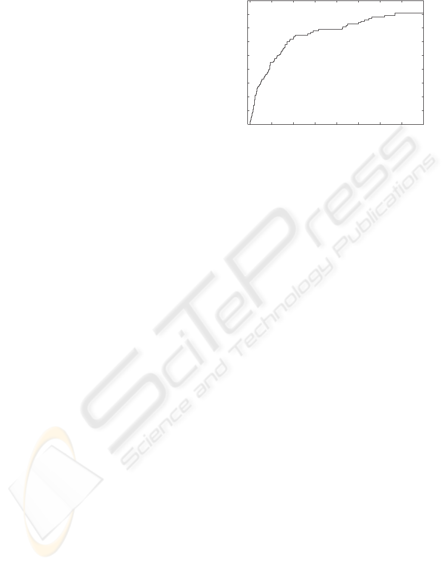
Figure 4: This diagram shows the learning of Wall-
Following behaviour. During learning 93 RLAs were cre-
ated in phase 1 to adequately perform the desired behaviour.
If d
i
is large, just a small difference of s
i
− k
i
could
lead to a penalty point value outside of the similarity
radius. If d
i
= 0 however, then the corresponding sen-
sor to s
i
has no influence on the penalty points. This
sensor is not necessary to perform the specified be-
haviour. To distinguish between RLAs of the differ-
ent behaviours, d
20
is chosen disproportionally high,
so that the penalty points of another behaviour’s RLA
are always outside the similarity range. That means a
RLA could only gain control when the robot performs
the specific behaviour that the RLA was created for.
3.2 Creating New RLAs
When the robot is stopped because of an unknown
situation, we have to find a condition C for the new
RLA, that describes the current situation S of the
robot. Because the vector S and the new condition
C vector K have the same structure, we can take the
present situation S as the new vector K, and get the
best possible description of the situation S therefore.
After that we need an adequate action A for the new
RLA. Because the system is in a supervised learning
modus, it waits for a teacher’s command. The teacher
is able to see the robot in its environment, assess the
situation, and set the correct motor commands. These
motor commands can then be copied into the action
part A of the new RLA. After that, this new RLA
automatically becomes the ”winning” RLA, and the
new motor command A can be performed. In the next
round, the subsequent situation can taken to be the ex-
pectation E of the new RLA. Therefore section E of
the RLA has the same structure as the situation S and
the condition C part.
In addition to this, a RLA network is created,
which contains all RLAs as nodes. An edge (X,Y)
represents a relationship between RLA X and RLA
Y. RLA X is an antecessor of RLA Y and RLA Y a
ICINCO 2007 - International Conference on Informatics in Control, Automation and Robotics
350
Robot KURT2
Controller
Upstream
Downstream
P
r
e
p
r
o
c
c
e
s
s
i
n
g
M
o
t
o
r
c
o
m
m
a
n
d
s
Sensors Motors
Pocket PC
User
commands
C
A
E
x
x
x
C
A
E
y
y
y
C
A
E
z
z
z
Figure 5: This diagram shows the system used in phase 1
and 2. The controller manages the RLA system and a RLA
network with probabilities of transitions between the states.
successor of RLA X. The edges also have weights.
A weight of an edge (X,Y) represents the probability
of Y being successor of X. Self references (meaning
RLA X follows RLA X) are not considered. Thus the
sum of the weights of a node’s output edges is 1.
In this training phase, the rate of creating new
RLAs is very high. The robot reaches unknown sit-
uations very often, because it must build up all of
the knowledge needed to perform a behaviour. The
rate steadily decreases however, until the robot knows
most of the situations reached by a behaviour (see fig-
ure 4. The end of each training phase is determined
by the teacher.
4 PHASE 2- BUILD-UP TRAINING
During the first phase, it is possible that the teacher
may have made mistakes, such as sending the incor-
rect motor commands, or misinterpreting the robot’s
situation. The purpose of the second phase is to im-
prove the RLA system by correcting these mistakes,
as well as getting to know some special situations not
encountered in phase 1. At the end of this learn-
ing section the robot is able to perform the learned
behaviour, and to plan its actions reactively to the
teacher’s satisfaction. After the teacher finishes this
phase, the learning of this behaviour is finished as
well. There are three ways in which the teacher may
influence the robot’s behaviour:
1. Changing a RLA’s action command A
The teacher may interrupt the robot when he no-
tices that a RLA has a false action command. The
robots stops and asks for a new action command
A, which overrides the old action command of the
current RLA. This modification should be made,
if the RLA’s action is ever inadequate.
2. Creation of a RLA in a known situation
The teacher can instruct the robot to create a new
RLA, forcing the robot improves its movement
skills. This helps the robot to distinguish between
more situations, thus enabling it to act more pre-
cisely.
3. Creation of a RLA in an unknown situation
This is the same modification of the RLA system
as described in the first learning phase.
The two phases 1 and 2, can be seen as two parts
of one single supervised training phase. It is not
generic to divide the supervised learning into the two
phases like we did. During the experiments with the
real robot we made the observation that the training
changes its character after some initial training steps
(pase 1), and the subsequent training (phase 2) was
different. Within phase 1 the robot stops very of-
ten, demanding for new RLAs to be created. After
a while, the robot performs well, performing a rudi-
mentary version of the given task, and stops rather
seldom for getting a new RLA. This observation is
the motivation behind the two learning phases 1 and
2. Further investigations are necessary to clarify the
observed effect.
5 PHASE 3- REINFORCEMENT
LEARNING
In this phase the robot learns how to evaluate a situa-
tion, based on reinforcements provided by the teacher
((Sutton and Barto, 1998)). The robot begins by per-
forming one of its various behaviours just as it learned
it in phases 1 and 2. If the robot reaches a situa-
tion that the teacher regards as valuable, the teacher
will then send a reinforcement of either ”Good”, or
”Bad”. When the teacher assesses a situation as being
good in terms of the associated behaviour, he should
reinforce it as ”Good”. Critical situations or situa-
tions which were handled less effectively by the robot
A HUMAN AIDED LEARNING PROCESS FOR AN ARTIFICIAL IMMUNE SYSTEM BASED ROBOT CONTROL -
An Implementation on an Autonomous Mobile Robot
351
should be reinforced as ”Bad”. The robot’s task in this
phase is to perform a behaviour and learn which situa-
tions were reinforced (as ”Good” or as ”Bad”) so that
it could provide its own reinforcements in the fourth
learning phase.
5.1 Reinforcement-RLAs
In order to learn reinforcements, the robot must
be able to memorise situations and to associate
them with evaluations. Therefore we use a mod-
ified form of a RLA: a Reinforcement-RLA. The
Reinforcement-RLA associates a situation with a re-
inforcement, and consists of only two parts: A situa-
tion describing part C and an action part implemented
as reinforcement-part R.
Just as in the previously mentioned RLAs, the
condition C part is represented by a 21 dimensional
vector. The reinforcement part R consists of a rein-
forcement signal (”Good” or ”Bad”).
5.2 Creating a New
Reinforcement-RLA
When the teacher gives a reinforcement signal, the
PDA sends it to the robot, and the robot creates a
new Reinforcement-RLA. The content of the new
Reinforcement-RLA’s C part (in the form of a 21
dim vector) is the upstream output (vector S). This
represents the current situation, which has been rein-
forced. The reinforcement signal received from the
PDA is stored in the reinforcement part R of the new
Reinforcement-RLA. With this procedure, the robot
creates a set of Reinforcement-RLAs, one for each
given reinforcement.
6 PHASE 4 - UNSUPERVISED
REINFORCEMENT
In this phase the robot should generate a reinforce-
ment signal for its current situation by itself (unsu-
pervised). At this point it utilizes of a set of RLAs
to perform reactive action planning, and a set of
Reinforcement-RLAs to evaluate its own situations
accoring to phase 3.
6.1 Reinforce a Situation
The robot performs its reactive action planning ac-
cording to a behaviour, and every subsequent situation
it reaches is then compared to the conditions C of the
Reinforcement-RLAs. This comparison is executed
Robot KURT2
Upstream
Downstream
P
r
e
p
r
o
c
c
e
s
s
i
n
g
M
o
t
o
r
c
o
m
m
a
n
d
s
Sensors Motors
Pocket PC
User
commands
C
A
E
x
x
x
C
A
E
y
y
y
C
A
E
z
z
z
Controller
C
a
R
a
C
b
R
b
C
e
R
e
C
d
R
d
C
f
R
f
Figure 6: This diagram shows the complete system. The
controller manages the RLA system, the Reinforcement-
RLAs, and a RLA network with transition’s probabilities
and evaluations.
in the same way as described in section 3.1. If any
C section of a Reinforcement-RLA is similar enough
to the current situation, the respective reinforcement
signal in the reinforcement part R is used to evaluate
this situation. The procedure is as follows:
1. The penalty points between the current situation
and all Reinforcement-RLAs’ C parts are built.
The attention focus of this behaviour is the same
used in phase 1 and 2.
2. The Reinforcement-RLA with the lowest penalty
points is deemed the best.
3. A reinforcement radius is set to express a mea-
sure of similarity. If the penalty points are lower
than the reinforcement radius, then the situation
could be evaluated with the reinforcement signal
saved in the part R of the best Reinforcement-
RLA. If the penalty points are higher than the
Reinforcement-radius, no reinforcement signal is
given and the robot could continue reactively
planning its actions.
ICINCO 2007 - International Conference on Informatics in Control, Automation and Robotics
352

6.2 Consequences of a Reinforcement
Signal
With the reinforcement signal, the robot evaluates its
previous actions and transitions of states, and there-
fore creates a new RLA network. This network has
the same structure as the one described in section 2.2:
Nodes represent RLAs (not Reinforcement-RLAs)
and the edges represent transitions of RLAs. These
transitions could be interpreted as transitions between
states. However, instead of attaching probabilities of
these transitions, we log a weight w for their value.
Every time the robot extracts a reinforcement signal,
it evaluates the most recently used transitions. There-
fore a RLA network is initialised where all edge’s
weights w
(x,y)
= 100. To reinforce a state’s transition,
we define reinforcement factors r f
j
for ”Good” and
”Bad” reinforcements, where j is an natural number
that represents the distance to the reinforced state. Af-
ter a reinforcement signal is given, we can update the
weights w
(x,y)
of the previous transitions as follows:
w
(x,y),i+1
= w
(x,y),i
· r f
j
For example, an episode of RLA W, RLA X,
RLA Y and RLA Z with a ”Good” reinforcement
signal is given while RLA Z was performed. The
reinforcement-factors r f
j
for a ”Good” reinforcement
should be r f
1
= 0.9, r f
2
= 0.95 and r f
3
= 0.97. The
values in the RLA network are then updated as fol-
lows:
w
(y,z),i+1
= w
(y,z),i
· 0.9
w
(x,y),i+1
= w
(x,y),i
· 0.95
w
(w,x),i+1
= w
(w,x),i
· 0.97
Therefore we receive a RLA network whose
weights represent the effectiveness of a transition.
If w
(x,y),i
< 100, thetransition between RLA X and
RLA Y is preferred. The lesser the value of w
(x,y),i
the
better the transition. If w
(x,y),i
= 100, thetransition be-
tween RLA X and RLA Y is neutral. If w
(x,y),i
> 100,
the transition between RLA X and RLA Y is avoid-
able. The higher the value of w
(x,y),i
the worse the
transition.
We call this RLA network ”effectiveness net-
work”, and the RLA network described in section 3
as containing the probabilities is called ”probability
network”.
The probability network is built during all four
phases of learning, but the effectiveness network is
only built in the fourth phase. The robot performs re-
active action planning, and evaluates the situations it
reaches. This fourth phase could last life-long, be-
cause at this point the robot is autonomous and no
longer requires a teacher.
7 RESULTS OF EXPERIMENTS
We trained three behaviours to show the practicability
and the effectiveness of our learning process. We used
three different types of attention focus:
1. (3, 3, 3, 3, 3, 0, 0, 0, 0, 0, 0, 0, 0, 0, 0, 0, 0, 0, 0, 0, 50)
2. (2, 2, 2, 2, 2, 5, 5, 1, 1, 1, 1, 1, 1, 1, 1, 1, 1, 1, 1, 1, 50)
3. (1, 1, 1, 1, 1, 7, 7, 5, 5, 5, 1, 1, 1, 1, 1, 7, 7, 5, 5, 5, 50)
7.1 Collision Avoidance
In this behaviour we used attention focus number 1
which considers only front sensors. With this we can
simulate a braitenberg vehicle (Braitenberg, 1986) to
achieve a collision avoidance behaviour. All other
sensors are suppressed.
The robot achieved a satisfying collision avoid-
ance behaviour with 21 RLAs, 13 of them were cre-
ated during the first phase of learning. The robot took
8:20 minutes to learn this behaviour. (see table 7.4).
The teacher created 11 Reinforcement-RLAs in
the third phase, which lasted for five minutes. These
Reinforcement-RLAs were used by the robot to eval-
uate situations by itself for another 15 minutes. After
this fourth phase of learning, the best transition in the
robot’s effectiveness network had a value 0.01 and the
worst 159.
7.2 Wall-Following
This behaviour is a left-handed Wall-Follower and the
robot learned it with attention focus number 2. This
behavior considers the position sensors the most, and
the front sensors were necessary to perform in con-
cave edges.
The robot achieved a satisfying wall-following be-
haviour with 92 RLAs, 81 of which were created dur-
ing the first phase of learning, which lasted 11:07
minutes. There were only a few new RLAs created in
extraordinary situations in the second phase of learn-
ing. (see table 7.4).
The teacher created 12 Reinforcement-RLAs in
the third phase, which lasted for five minutes. These
Reinforcement-RLAs were used by the robot to eval-
uate the situations it reached by itself for another 10
minutes (see table 7.4). After this fourth phase of
learning, the best transition in the robot’s effective-
ness network had the value 80.26 and the worst 826.
This high negative value is caused by a situation in
which the robot is too close to a wall, which it cor-
rects in the next step. This situation occurred very
often.
A HUMAN AIDED LEARNING PROCESS FOR AN ARTIFICIAL IMMUNE SYSTEM BASED ROBOT CONTROL -
An Implementation on an Autonomous Mobile Robot
353
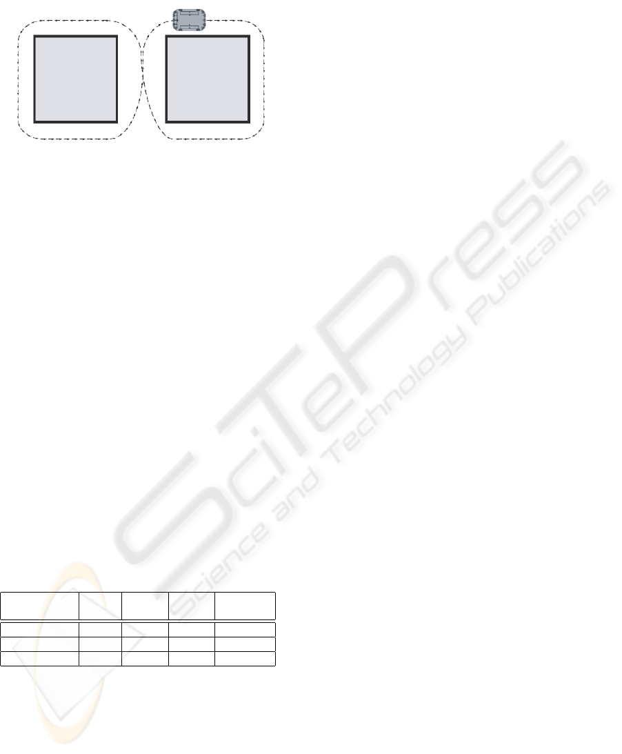
7.3 Drawing an 8
Figure 7: This figure shows the 8-drawing behaviour. The
robot must perform two different kinds of wall-following
behaviours.
The 8-drawing behaviour combines a left-handed
and a right-handed Wall-follower. To teach this be-
haviour, we used attention focus number 3, which
considers the positioning sensors, the object-detection
sensors and the history as very important. The robot
achieved a satisfying 8-drawing behaviour with 127
RLAs in 12 minutes (see table 7.4). The teacher
created 10 Reinforcement-RLAs in the third phase,
which lasted five minutes. The robot used these
Reinforcement-RLAs to evaluate the situations it
reached by itself for another 10 minutes. After this
fourth phase of learning, the best transition in the
robot’s effectiveness network had the value 35.35 and
the worst 100. This means that either a negative re-
inforcement was not given, or it was neutralised by a
positive reinforcement.
7.4 Performance
Table 1: Results of the first and second phase learning
for the three different tasks: Collision Avoidance, Wall-
Following, Draw an 8. The time is the sum of learning time
for phase 1 and for phase 2.
Task Att. Sim. No of Time
focus radius RLAs 1+2
Avoid 1 16 21 8:20 min
Wall-Follow 2 16 92 26 min
Draw an 8 3 16 127 12 min
All behaviours were learned to the teacher’s satis-
faction. The robot performed in real-time and was
very effective in learning its behaviours. All be-
haviours could be taught by an amateur user in rea-
sonably short time. After these learning phases, the
robot was able to deliberately and actively plan its
next actions, based on the trained RLA network with
the probability and/or the effectiveness network (Sut-
ton and Barto, 1998).
8 CONCLUSIONS
Within this paper we presented a novel approach of
creating bahaviour based robot controllers. Based
on an artificial immune sytem inspired RLA system,
the learning process starts with supervised learning
via reinforcement learning and reaches unsupervised,
autonomous learning capabilities. We have demon-
strated, that the presented paradigm is capable of
teaching tasks with different complexity with a real
robot in reasonably short training time, even for a
non-expert robot end-user. Several aspects of the
presented works are still open for further interesting
investigations: find an universal attention focus,
investigate the 2 phases of supervised learning,
planning with the use of the RLA network.
The authors are convinced that the presented
works is an powerfull alternative to design and train
behaviour based robot controllers. The final goal to
get rid of the nasty ”low-level” robot programming
has come one step further into reach.
We do no longer programm our robot:
We teach the tasks by showing the actions and
judge the performed behaviour.
REFERENCES
Arkins, R. C. (1998). An Behavior-based Robotics. The
MIT Press.
Braitenberg, V. (1986). Vehicles- Experiments in Synthetic
Psychology. The MIT Press.
Goerke, D. N. (2001). Perspectives for the next decade of
neural computation. In Proc. of NATO Advanced Re-
search Workshop on: Limitations and Future Trends
in Neural Computation (LFTNC’01), pages 1–9.
Hart, E., Ross, P., Webb, A., and Lawson, A. (2003). A
role for immunology in ’”next generation”’ robot con-
trollers. In ICARIS03, Artificial Immune Systems, Sec-
ond International Conference, pages 46–56.
KTO (1995). KTO- Kommunikation und Technologietrans-
fer Odenthal. http://www.kurt2.de/.
Rattenberger, J., Poelz, P. M., Prem, E., Hart, E., Webb, A.,
and Ross, P. (2004). Artifical immune networks for
robot control. In Proc Fourth Int Workshop on Epige-
netic Robotics: Modeling Cognitive Development in
Robotic Systems, volume 117, pages 151–154.
Ross, P. (2003). Notes on the RLA network implementa-
tion. Technical report, Napier University, Scotland.
Sutton, R. S. and Barto, A. G. (1998). Reinforcement Learn-
ing: An Introduction. The MIT Press.
Webb, A., Ross, P., Hart, E., and Lawson, A. (2003). Gener-
ating robot behaviours by evolving immune networks.
Technical report, Napier University, Scotland.
ICINCO 2007 - International Conference on Informatics in Control, Automation and Robotics
354
