
MODIFIED DISTANCE SIGNATURE AS AN ENHANCIVE
DESCRIPTOR OF COMPLEX PLANAR SHAPES
Andrzej Florek and Tomasz Piascik
Institute of Control and Information Engineering, Poznan University of Technology, 60-965 Poznan, Poland
Keywords: Shape description, signature, object recognition, classification.
Abstract: In this paper, a simple and efficient approach to classify planar shapes is proposed. This approach is based
on comparison of areas of dynamicly sampled classic signatures. Presented approach is dedicated to the
recognition of convex and concave planar shapes, containing openings in the area enclosed by boundary.
A way to calculate the discrete representation of classic distance-versus-angle signatures, a reduction of
memory requirements and a number of calculations are presented. Analysis carried out from classification
experiments applied to images of real objects (car-engine collector seals) indicates good properties of
dissimilarity coefficients, based on modified signature, taken as an object descriptor.
1 INRODUCTION
The way of representing visual information
concerning the objects found in the scene plays
a fundamental role in the process of recognition and
classification. One of the most essential
characteristics enabling the recognition of an object
is a shape. That is why the analysis of the scene
often leads to the patterns comparison and to the
recognition of object shapes. The shape analysis is
linked with the problem of appropriate
representation of the shape and the methods of its
description (Demant, 1999), (Gonzales, 1992). The
methods of the shape describing are fundamentally
based on information concerning its contour or
information about its area as a whole. The object
description should be invariant with regard to
translation, rotation and scale change. Apart from
clarity, selectivity and precision, a good shape
descriptor should have low computation complexity
and universal application (Gonzales, 1992), (Zhang,
2004). The above-mentioned features of a good
descriptor are often contradictory.
In the following, the global approach towards the
shape description based on boundary by using
centroid distance signature is presented. The
modified principle of calcutating shape signature
and comparison with a standard approach is also
discussed. The algorithm efficiency of examining
the similarity both of convex and concave objects
and objects with openings is given. Application of
the modified signature in the process of recognition
is illustrated by classifying the images of car-engine
collector seals.
2 CENTROID DISTANCE
SIGNATURE AND ITS AREA
The classic shape signature is a 1D function
representing a 2D shape bordered by a contour. The
subject of discussion is the shape signature using the
distance of contour pixels from the defined reference
point. The standard example is the distance between
contour pixels and the center of gravity of the
contour (or whole figure) as the function of the angle
(Gonzales, 1992). This definition of the descriptor is
suitable for representing convex shapes. In many
concave or disconnected shapes (e.g. for objects
having holes), we obtain more than single distance
value for the same angle
φ
. In a general case, the
signature is a mapping of the angle into a distance
set and the shape signature is represented by ordered
series of pairs S={(
φ
i
, R
i
)}. To obtain R
i
values,
a continuous signature must be sampled. In a classic
approach, sampling is done at a constant step
Δφ
= 2
π
/N, where N is an assumed angular
resolution. As a result, sampled signature
representation S={(i
Δφ
, R
i
), i=1, ..., N} is obtained.
225
Florek A. and Piascik T. (2007).
MODIFIED DISTANCE SIGNATURE AS AN ENHANCIVE DESCRIPTOR OF COMPLEX PLANAR SHAPES.
In Proceedings of the Second International Conference on Computer Vision Theory and Applications - IU/MTSV, pages 225-230
Copyright
c
SciTePress

In a general case, more R
ik
for a given i
Δφ
be
obtained (Parker, 1998).
The approach proposed here consists of tracking
the contour pixel by pixel and building a signature
taking into account the local dynamics of the
contour. With this approach sampling is performed
at a variable step. The algorithm of shape signature
determination consists of the following steps:
1. Extracting all object contours.
2. Calculating coordinates of a chosen reference
point P
R
(x
R
, y
R
).
3. Tracking an external contour C.
4. For each pixel C
j
(x
j
, y
j
), calculating a distance
R
j
from the point P
R
and an angle
φ
j
as arctan(( y
j
– y
R
)/(x
j
– x
R
)) and storing them
in a signature mapping table S[
φ
j
, R
j
].
5. Determining a maximal distance R
MAX
.
6. Rewriting chosen normalized values R
j
/R
MAX
to a modified signature table.
7. Repeating the whole procedure for all internal
contours of openings in the analyzed object
(steps 4-6).
The choice of consecutive points from the
signature mapping table S[
φ
j
, R
j
], to rewrite them
into the modified signature table, is determined by
three parameters, which describe sampling process:
Δ
R/R − the relative pixel distance change
parameter between consecutive signature
points (the fundamental sampling condition
meaning that for consecutive point
|
R
j+1
−
R
j
|
/ R
MAX
≥
Δ
R/R );
φ
MIN
− the minimal angle change between
signature samples (a condition guaranteeing
that between consecutive modified signature
points the angle increment will not be less
then a predefined value
|
φ
j+1
-
φ
j
|
≥
φ
MIN
);
φ
MAX
− the maximal angle change (the angle
increment will not be greater then a predefined
value
|
φ
i+1
-
φ
i
|
≤
φ
MAX
).
This process determines a modified signature
taking into account the dynamics of the shape. For
Δ
R/R = 0 classic shape signature is obtained for step
Δφ
=
φ
MIN
. The choice of the reference point P
R
should not be accidental to ensure the invariance
with regard to the object translation in the frame.
The less subject to disruption the location of P
R
, the
more precise the descriptor. The normalization with
respect to R
MAX
lets the descriptor to be invariant
regards to the scale change.
In the presented approach, the essential element
for signature comparison is the signature area. In the
case of some convex shapes, the signature area
corresponds to the area delimited by a curve built of
signature points. In the case of some concave objects
and objects with openings, in order to determine the
signature area, there is a need for interpolation of the
modified signature. This is a consequence of the
variable sampling rate and the independent external
and internal contours tracking. After extending the
modified signature to each spike, the appropriate
region filling is made (Fig. 1). At this stage, the
information from contour tracking algorithm is used.
3 SIMILARITY OF PLANAR
OBJECTS
Object similarity analysis, while signatures represent
shapes, refers to the comparison of signature areas
(Parker, 1998). For comparison the XOR operation
between the spikes of two signatures is used.
Comparison is made with respect to the
corresponding values of scanned angles. The
calculated difference between areas is related to the
reference area and this relative symmetric area
difference is taken as a coefficient of non-similarity
of compared shapes (DISS coefficient). As the
reference area, an area of the box bounding signature
or an area of one of the compared signatures is
taken. To suppress nonlinear effects, due to the
transformation from the Cartesian coordinate system
to the polar coordinate system, R
j
2
/R
2
MAX
values in
XOR operation are used, while calculating signature
area. In this way, weight coefficient of an area pixel
is proportional to the pixel distance from the
reference point, as every area pixel represents the arc
length of circle section determined by
φ
MIN
and R
j
.
Such a coefficient is denoted as DISSW.
Rotational invariance is obtained by repeated
calculations of signature area differences, each time
cyclically translating one signature with respect to
the other. The minimum of calculated XOR values
(i.e. XOR value for the best matching of shape
signatures) determines the DISSW coefficient value
(3). With the classic approach, both signatures have
N spikes, for the same angle values. In the proposed
approach, modified signatures consist respectively
of N
1
≤
N and N
2
≤
N spikes. In the case of classic
signatures, N
2
comparisons are required (for N area
spikes and N shifts). In the proposed modification
case, only N
1
N
2
comparisons are performed, because
the second signature is shifted only N
2
times and
compared for N
1
angle values. Spikes are not
available for all angle values, thus to calculate XOR
area difference an interpolation has to be performed.
VISAPP 2007 - International Conference on Computer Vision Theory and Applications
226

4 EXPERIMENT DESCRIPTION
In order to validate the proposed approach to the
objects classification an experiment consisting of
examining a set of car-engine seals was undertaken.
In the experiment twelve seals (twelve classes of
objects) were used, for which twenty shots in several
varied positions were made (for various orientations
and projection scales). The scene was lit by two
lamps from above obliquely from two opposites
sides thus object edges cast slight shadows. After
preprocessing, tresholding and filtration with
a median filter 3×3, a set of 240 binary images of
objects was created (resolution 2 pixels/mm). The
first shot in each population for each class,
maintaining the same stable acquisition conditions,
produced image of class prototype. These prototypes
for twelve classes are shown in Fig. 2.
Comparison of classification methods using
classic and modified signatures was based on DISSW
value histograms comparison. Changes of class
discrimination measure, based on DISSW mean and
standard deviation values were analyzed.
4.1 Parameters of Analysis
For analyzed images, classic signature was
calculated for
Δφ
= 0.5°. For calculating modified
signature values
Δ
R/R ≤ 2.5% and
φ
MAX
= 5° have
been chosen. These parameters enable still
appropriate reconstruction of object contours.
Values of DISSW errors were calculated for all
prototypes of classes by using classic signature
comparison method. After analyzing these results,
two seal pairs with the smallest dissimilarity errors
were chosen. Comparison of classifiers based on
classic and modified signatures was executed for
pairs (H2, H4) and (D3, N2). Dissimilarity errors
were calculated for each image compared to the
others. If for ordered pair of classes (C1, C2) the sets
of their signatures are denoted as:
SC1 = {sc1
1
, sc1
2
, ..., sc1
20
}, (1)
SC2 = {sc2
1
, sc2
2
, ..., sc2
20
} (2)
where sck
i
is the signature for i
ih
image of the object
from Ck, then the dissimilarity errors for a pair
(C1, C2) are calculated for all i, j
∈ {
1, 2, ..., 20} as:
DISSW = min [( sc1
i
)
XOR(sc2
j
)] / sc1
i
.
(3)
First, errors in the standard case for
Δφ
= 0.5°
(N = 720) were calculated. Then, resolution was
decreased to
Δφ
= 1.5° (N = 240). These results are
compared to the errors obtained with the modified
signature, at
⎯
N
MOD
≈
N. Modified signatures were
calculated for:
φ
MIN
= 0.5°,
φ
MAX
= 5°,
Δ
R/R = 2%.
Experiment was performed for two reference points
(center of shape and center of boundary).
The calculated DISSW values are distorted by:
a transformation to the polar coordinate system,
a discretization, a tresholding (all being a method
error) as well as by optical deformations of camera
and shadows on the scene. The method error was
checked for standard case at
Δφ
= 0.5° with the
center of shape as the reference point. DISSW values
were calculated for prototype images analytically
transformed to positions corresponding to object
positions in the set of images for a given class.
These errors did not exceed 5%. The remaining
errors are regarded as a noise.
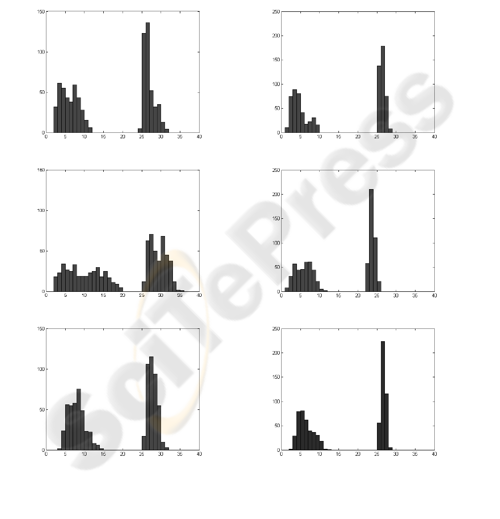
4.2 Analysis of Results
Analysis of experimental results is based on
comparison of mean and standard deviation values
(m,
σ
)
for within-class and between-class errors. In
Fig. 3, DISSW coefficient values histograms for pair
(H4, H2) are presented. In the standard case for
shape center and for
Δφ
= 0.5° (named as an
accurate case), calculated values of statistical
parameters (m,
σ)
of DISSW values are as follows:
( 6.0, 2.3) for (H2, H2);
(28.0, 1.4) for (H2, H4);
( 6.1, 2.4) for (H4, H4);
(26.9, 1.5) for (H4, H2).
To compare both classic and modified methods,
a dispersion measure of classes (C1, C2)
is defined
as:
D (C1,C2) = |m
C11
− m
C12
|(
σ
C11
2
+
σ
C12
2
)
− 0.5
,
(4)
where m
C11
,
σ
C11
2
are the mean and the variance of
(C1, C1) within-class DISSW values and m
C12
,
σ
C12
2
are the mean and the variance of (C1, C2) between-
class DISSW values, respectively.
Calculated values of D are presented in Tab. 1.
In the standard case (
Δφ
= 1.5°), for pairs (H2, H4)
and (H4, H2), value of the measure D decreases,
nearly twice. In the modified signatures case, at the
same number of signature spikes, value of the
dispersion measure D increases with respect to
standard case (
Δφ
= 1.5°) and is even bigger then in
the accurate case (
Δφ
= 0.5°). The results for the
pair (D3, N2) change in a similar manner.
MODIFIED DISTANCE SIGNATURE AS AN ENHANCIVE DESCRIPTOR OF COMPLEX PLANAR SHAPES
227
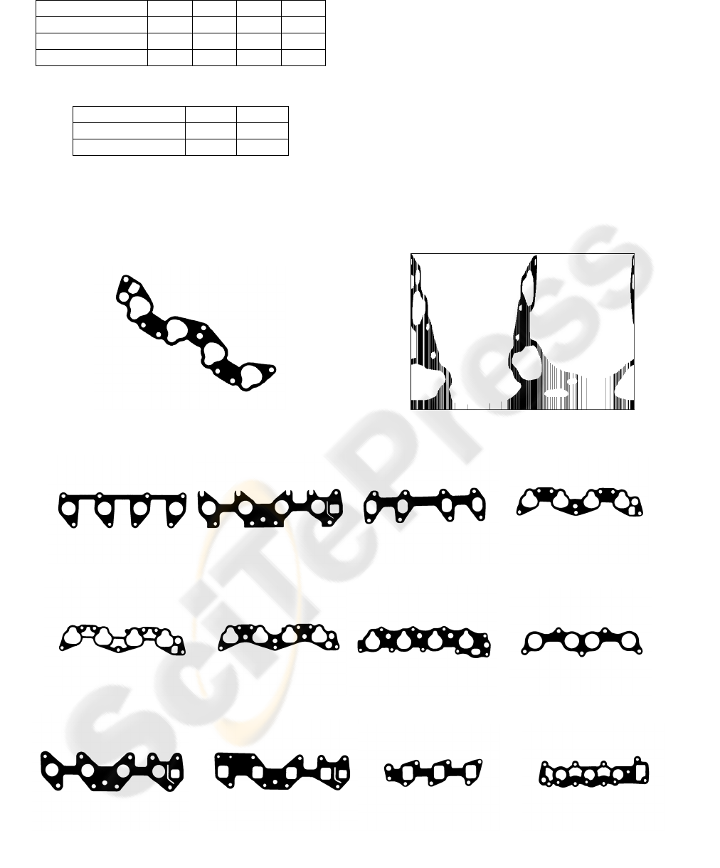
Table 1: Values of dispersion D for center of shape.
Method H2 H4 H4 H2 D3 N2 N2 D3
Classic
Δφ
= 0.5° 8.1 7.4 9.0 9.8
Classic
Δφ
= 1.5° 4.5 3.8 7.3 7.8
Modified 8.5 8.0 9.0 9.9
Table 2: Values of dispersion D for center of boundary.
Method H2 H4 H4 H2
Classic
Δφ
= 1.5° 2.1 2.4
Modified 2.9 4.2
Greater values of D and their smaller changes are
due to other type of shape and reduced radial
resolution. Applied radial resolution was always
equal to 1/500 R
MAX
, but objects from D3 and N2
classes have bigger absolute values R
MAX
then the
other ones.
Finally, results for modified and standard case
(
Δφ
= 1.5°) are compared while the reference point
was changed. Results for pair (H2, H4), calculated
for center of external contour as the reference point,
are presented in Fig. 4 and Tab. 2. Increase of error
values and their standard deviation values can be
observed. For standard case, (m,
σ
) values of
DISSW coefficient are as follows:
(12.6, 5.7) for (H2, H2);
(27.0, 3.8) for (H2, H4);
(11.7, 4.7) for (H4, H4);
(25.9, 3.7) for (H4, H2).
Figure 1: Shape of a car-engine collector seal (left) and its modified signature (right).
d2
1
d3
1
f2
1
h2
1
h3
1
h4
1
h5
1
h6
1
n2
1
o2
1
s2
1
t2
1
Figure 2: Images of car engine collector seal class prototypes.
VISAPP 2007 - International Conference on Computer Vision Theory and Applications
228
This is due to the greater sensitivity of contour
center to the noise. For considered objects, the
number of contour pixels was 30 - 40 times smaller
that the number of pixels belonging to the object
shape. Decrease of angular resolution and increase
of noise level lead to overlapping between within-
class and between-class errors (in Fig. 4 common
area of histograms is marked by light gray color).
The modified signature improves the
discernability of classes. Tests performed on
modified signatures of real images reveal good
properties of the dissimilarity coefficient as an
object discriminator.
a)
b)
c)
Figure 3: Histograms of within-class and between-class dissimilarity errors for (H4, H2) – left and (N2, D3) – right,
for shape center as the reference point: a) classic Δφ = 0.5°, b) classic Δφ = 1.5°, c) modified
ΔR/R = 2%,⎯N
H4
= 250,⎯N
N2
= 237.
MODIFIED DISTANCE SIGNATURE AS AN ENHANCIVE DESCRIPTOR OF COMPLEX PLANAR SHAPES
229
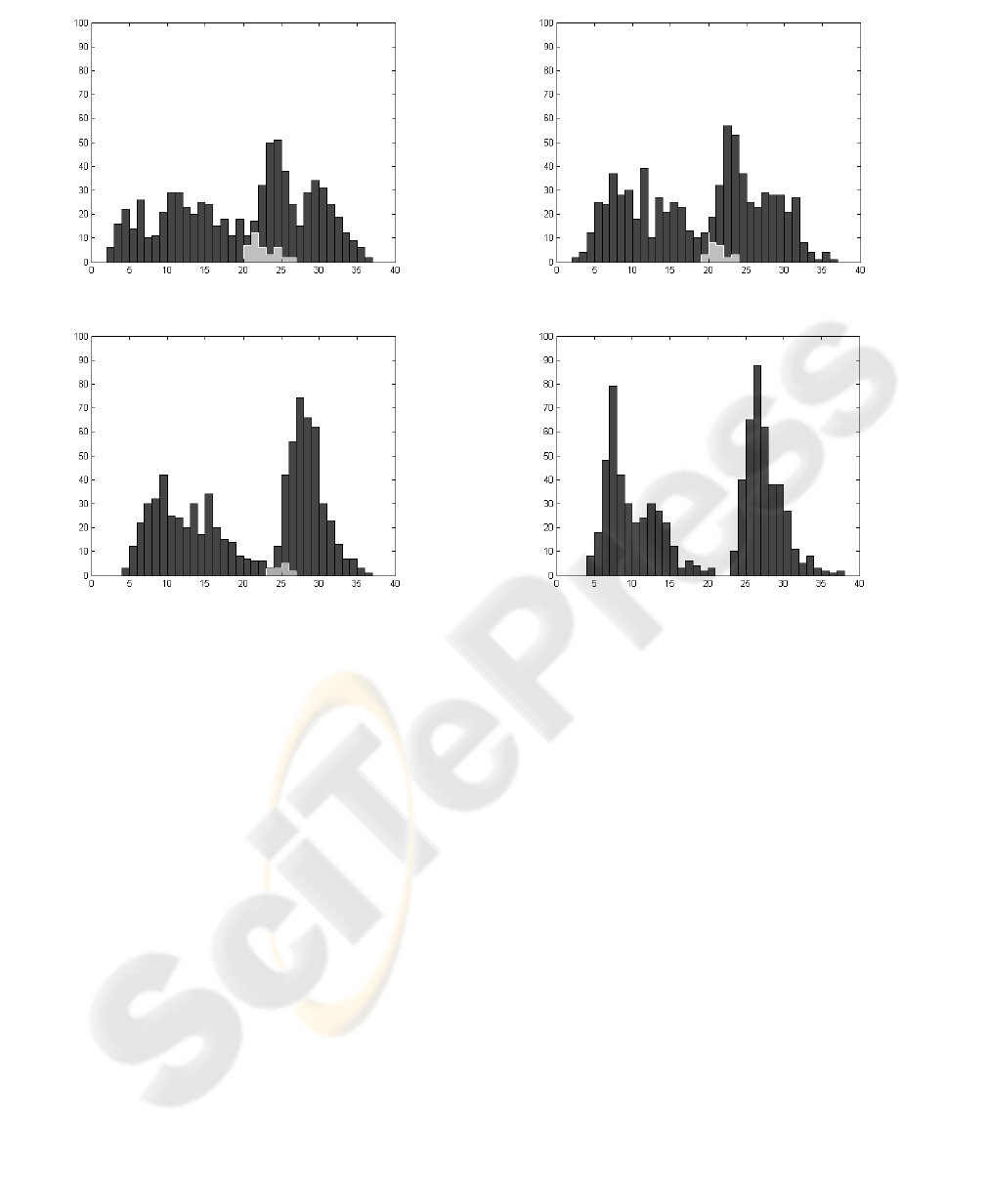
a)
b)
Figure 5: Histograms of within-class and between-class dissimilarity errors for (H2, H4) – left and (H4, H2) – right, for
boundary pixels center as the reference point: a) classic Δφ = 1.5°, b) modified ΔR/R
MAX
= 2%,⎯N
H2
= 242, ⎯N
H4
= 253.
5 SUMMARY
Application of the signatures of planar objects to
recognition and classification is simple, fast and
computationally effective. The presented method
of describing complex objects can be used in the
case of convex, concave and disconnected shapes
with openings. The modified shape descriptor is
invariant to translation and scale change, and the
mode of comparison assures its invariance with
regard to rotation. The proposed modified
approach takes into account the variability of
object contours leading to automatic changes in the
frequency of sampling of classic signatures. The
descriptor is directly connected with the shape of
the object. Parameter values taken to calculation of
the modified signature are simple to choose and the
validation of shape comparison results is natural.
The use of modified signatures reduces the
memory requirements and the number of
calculations without deteriorating recognition
results. Test undertaken on the real objects images,
indicates a good performance of the dissimilarity
coefficient determined with the modified signature
method. This coefficient enables good
discrimination of objects indicating the suitability
of this method for robotic inspection and visual
control systems.
REFERENCES
Demant, C., Streicher-Abel, B., Waszkiewitz, P., 1999.
Industrial Image Processing. Visual Quality Control
in Manufacturing, Springer Verlag, Heidelberg.
Gonzales, R.C., Woods, R.E., 1992. Digital Image
Processing, Addison-Wesley, Reading MA.
Parker, J.R., Zhang, Z., 1998. Object recognition using
signatures, Proc. IASTED Int. Conf. Signal and
Image Processing, Las Vegas, pp. 1-5.
Zhang, D., Lu G., 2004. Review of shape representation
and description techniques, Pattern Recognition 37
(1), pp. 1-19.
VISAPP 2007 - International Conference on Computer Vision Theory and Applications
230
