DISPARITY CONTOUR GROUPING FOR MULTI-OBJECT
SEGMENTATION IN DYNAMICALLY TEXTURED SCENES
∗
Wei Sun
Hewlett-Packard Laboratories, 1501 Page Mill Rd. ms 1181, Palo Alto, California 94304-1126, USA
Stephen P. Spackman
TimeSpring Software Corporation, 2000 Peel St. Suite 888, Montreal, Quebec H3A 2W5, Canada
Keywords:
Multi-object segmentation, stereo matching, background model, disparity verification, disparity contours.
Abstract:
A fast multi-object segmentation algorithm based on disparity contour grouping is described. It segments
multiple objects at a wide range of depths from backgrounds of known geometry in a manner insensitive to
changing lighting and the dynamic texture of, for example, display surfaces. Not relying on stereo reconstruc-
tion or prior knowledge of foreground objects, it is fast enough on commodity hardware for some real-time
applications. Experimental results demonstrate its ability to extract object contour from a complex scene and
distinguish multiple objects even when they are close together or partially occluded.
1 INTRODUCTION
Extracting moving objects from a static or dynamic
scene is useful in a wide variety of applications.
The particular case of isolating and distinguishing
multiple objects despite rapid changes in illumina-
tion and texture is particularly interesting for aug-
mented reality, immersive telepresence, and the enter-
tainment and film industry, where projected moving
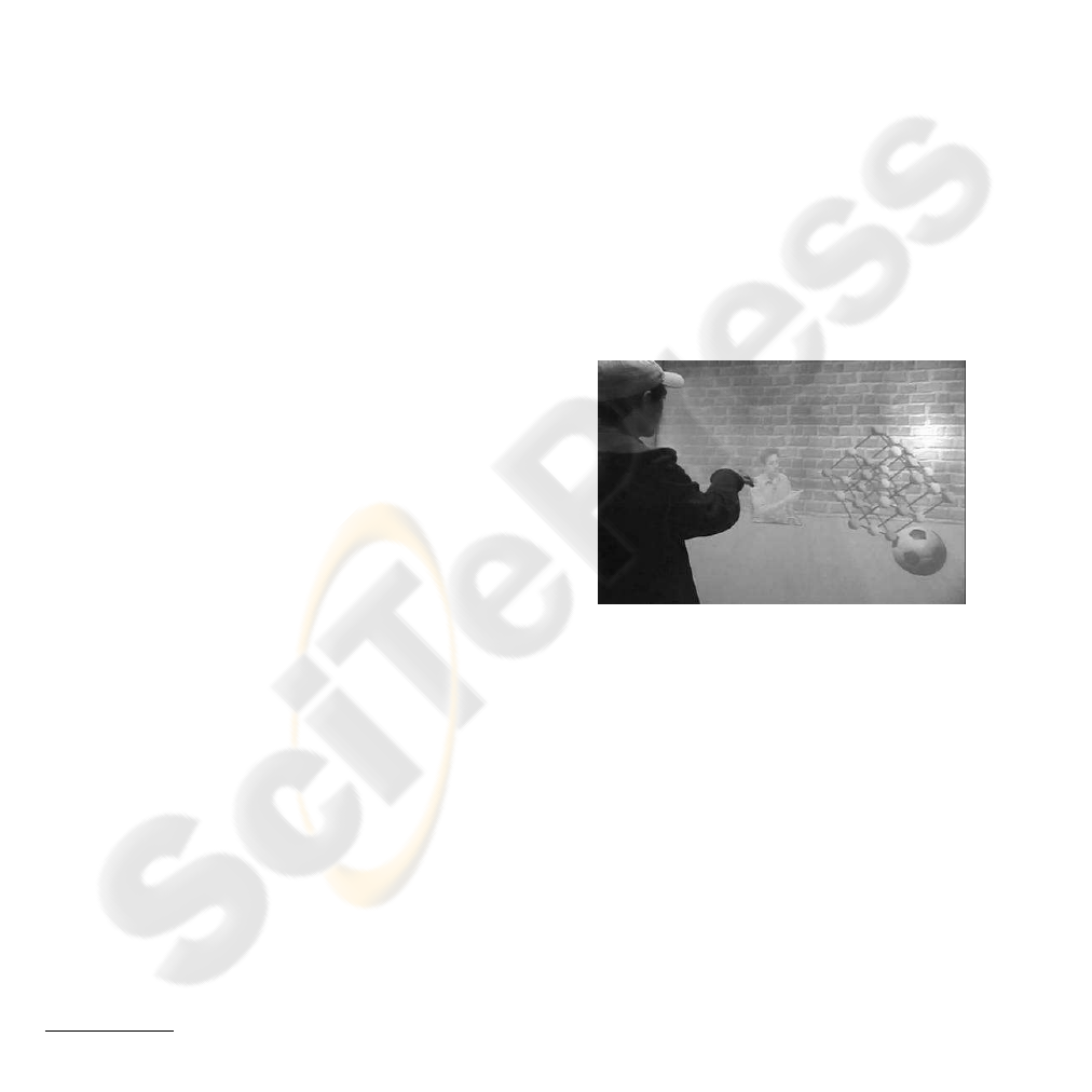
backgrounds are often present. An example is shown
in Fig. 1, where local and remote users interact with
each other and with virtual objects in a virtual world.
To successfully immerse users into this synthetic en-
vironment, it is necessary for the system to separate
them visually from their actual physical surroundings.
Single view background subtraction (Wren et al.,
1997; Stauffer and Grimson, 1999; Toyama et al.,
1999; Oliver et al., 2000; Rittscher et al., 2000; Cuc-
chiara et al., 2003) compares each image to a refer-
ence and labels pixels as background or foreground
based on a statistical model. Despite adaptability
to slow changes in lighting, texture, geometry and
shadow, these methods all assume background change
to be much less dynamic than foreground.
Layered motion segmentation (Wang and Adel-
∗
This research was carried out at the Centre for In-
telligent Machines, McGill University, Montreal, Quebec,
CANADA.
Figure 1: Example of an augmented reality environment.
son, 1993; Jepson and Black, 1993; Ayer and Sawh-
ney, 1995; Weiss and Adelson, 1996) decomposes im-
age sequences into sets of overlapping layers ordered
by depth, each described by a smooth optical flow
field. Discontinuities in the description are attributed
to moving occlusions, resulting in a 2.5D scene rep-
resentation. Unfortunately, the computation of opti-
cal flow is time-consuming, and these methods cannot
distinguish a real scene from a video.
Integrating multiple views is a natural alternative
for tackling dynamic environments, with added bene-
fits in handling occlusion. Some systems work from
3D reconstruction to object segmentation and track-
ing (Narayanan et al., 1998), and others combine seg-
mentation with stereo matching (Torr et al., 2001; Lin
and Tomasi, 2004). Sadly, frame-by-frame stereo re-
construction is also slow and so far unsuited to real-
347
Sun W. and P. Spackman S. (2007).
DISPARITY CONTOUR GROUPING FOR MULTI-OBJECT SEGMENTATION IN DYNAMICALLY TEXTURED SCENES.
In Proceedings of the Second International Conference on Computer Vision Theory and Applications - IU/MTSV, pages 347-354
Copyright
c
SciTePress

time use. Moreover, the uniform or repetitive tex-
tures common in indoor scenes and video-augmented
spaces constitute worst-case inputs for stereo match-
ing algorithms (Kolmogorov and Zabih, 2002; Sun
et al., 2003), often leading to disappointing results.
Attempts have been made to use stereo while re-
ducing computational cost. One of them combines
stereo with background subtraction and suggests dis-
parity verification for segmentation under rapid illu-
mination change (Ivanov et al., 2000). Using three
cameras on wide baselines, the method constructs of-
fline disparity mappings for the background images,
and at runtime separates foreground from background
by matching pixels corresponding in the mappings,
thus avoiding slow disparity search. Unfortunately,
the wide baseline setup, despite its effectiveness in ex-
tracting the entire foreground area, has difficulty fus-
ing multiple views of a target, which is essential for
tracking multiple moving objects. This weakness, in
the long run, also limits the method’s adaptability to
background geometry changes.
Another approach increases speed by decreasing
the number of disparity layers in stereo matching and
proposes layered dynamic programming and layered
graph cut for foreground/background separation (Kol-
mogorov et al., 2005). Although tolerance of back-
ground motion has been demonstrated, published re-
sults show only cases with a substantial depth differ-
ence between background and foreground, with fore-
ground objects very close to the camera. This is a
strong limitation for many real-world applications.
Both fast stereo approaches, however, stop at bi-
layer pixel labelling, and do not attempt to distinguish
multiple objects. The additional processing required
for accurate object location would be extensive.
This paper presents a new background subtraction
based stereo segmentation system that can isolate and
distinguish multiple objects in the presence of highly
dynamic lighting and background texture. In addi-
tion to the advantage of bypassing full stereo recon-
struction and achieving fast performance, it adopts a
small baseline setup and extracts disparity contours.
These directly provide object boundaries, and also al-
low fast, incremental disparity adjustment for objects
at different depths. The method has the potential to
provide support for 2D and 3D object tracking and
background geometry update.
2 DISPARITY CONTOURS
Before we explain our system in detail, we introduce
the disparity contours resulting from small baseline
stereo background subtraction. We then show how
to estimate foreground disparity and verify object hy-
potheses based on extracted disparity contours.
2.1 Background Hypothesis
Falsification (BHF)
The 3D layout of a background is represented by a
background disparity map (BDM) describing the
relative displacement, or disparity, of pixels corre-
sponding to the same background point in each cam-
era view. The images are undistorted and rectified so
that pairs of conjugate epipolar lines become colinear
and horizontal (Fusiello et al., 2000). This brings the
pixels originating from a scene point s to a common
scanline, falling at (x
L
(s), y(s)) in V
L
, the left view,
and (x
R
(s), y(s)) in V
R
. We call the difference
x
L
(s) − x
R
(s) = d
B
(s), (1)
increasing with proximity to the camera, the back-
ground disparity at s, and define the BDM to be
BDM =
{h
x
L
(s), x
R
(s), y(s)
i}
, (2)
where s ranges over background scene points visible
to either camera and in their common field of view.
Given the BDM for two cameras, each new pair
of captured images are hypothesized to be of back-
ground alone, and a view difference map (VDM)
computed from the stored correspondences by block
matching, using a vertical stripe window to maintain
contour widths and aggregate neighborhood support:
VDM
BHF
(x
L
, x
R
, y) =
∑
u,v
|
V
L
(x
L
+ u, y+ v) − V
R
(x
R
+ u, y+ v)
|
,
where y
L
= y
R
= y and
h
x
L
, x
R
, y
i
∈ BDM. (3)
If the images are well synchronized, this operation
cancels instantaneous background texture.
Thus, ideally, VDM
BHF
(x
L
, x
R
, y) = 0 where a
scene point s is truly part of the background, but is
larger if either of the pixels V
L
(x
L
, y) and V
R
(x
R
, y)
belongs to a foreground object. Thus a value signifi-
cantly different from zero leads to the falsification of
the hypothesis that the BDM is an accurate local de-
scription at a given scene point.
In reality, the result depends on the visual dif-
ference between background and foreground, be-
tween different foreground objects, and between
points within foreground objects, as illustrated in
Fig. 2. Suppose
h
a
L
, a
R
, y
i
,
h
b
L
, b
R
, y
i
,
h
c
L
, c
R
, y
i
and
h
d
L
, d
R
, y
i
are entries on the y
th
scanline in the BDM.
At object boundaries, segments [(a
L
, y), (b
L
, y)] and
[(c
L
, y), (d
L
, y)] in the left image are mismatched
against segments [(a
R
, y), (b
R
, y)] and [(c
R
, y), (d
R
, y)]

Figure 2: Background hypothesis falsification. Mismatch
occurs at object boundaries and interiors.
in the right, respectively. In object interiors, seg-
ment [(b
L
, y), (c
L
, y)] is mismatched against segment
[(b
R
, y), (c
R
, y)].
As most (non-camouflaged) real-world objects
are texturally coherent, we find that foreground-
background mismatches at object boundaries have
higher intensity than those from object interior au-
todecorrelation, as visible in Fig. 9(b). Further, since
boundary mismatches derive from the geometry of
projection, they also have more regular shape. We
now examine these boundary mismatches in detail.
2.2 Disparity Contours
At object boundaries, stereo mismatch arising from
background hypothesis falsification forms contours,
as illustrated in Fig. 3. Since disparity increases with
proximity to the cameras, the width of the contour
area in which background is mismatched against fore-
ground depends on how poor the assumption of back-
ground was, in terms of depth error.
Consider, without loss of generality, the left view.
According to Fig. 2 and Eq. (1), we have
x
L
(a
L
) − x
R
(a
R
) = d
B
(a
L
). (4)
Since b
L
and a
R
map to the same foreground point,
x
L
(b
L
) − x
R
(a
R
) = d
F
(b
L
), (5)
where d
F
(b
L
) is the foreground disparity at b
L
. Sub-
tracting Eq. (4) from (5) and eliminating x
R
(a
R
),
x
L
(b
L
) − x
L
(a
L
) = d
F
(b
L
) − d
B
(a
L
). (6)
Similarly,
x
L
(d
L
) − x
L
(c
L
) = d
F
(d
L
) − d
B
(c
L
). (7)
This means that the lengths of the segments
[(a
L
, y), (b
L
, y)] and [(c
L
, y), (d
L
, y)] are exactly the
differences between the foreground and background
disparities at the object boundaries, and encode depth.
Combining such segments vertically as in Fig. 3 will
yield the depth-encoding contours of foreground ob-
jects, referred to as disparity contours. As the figure
Figure 3: Disparity contours from background hypothesis
falsification. Contour widths equal differential disparities
between object and background.
makes clear, the resulting contours lie at the left of
object boundaries in the left image but at the right in
the right image. There is thus no ambiguity in the
boundary locations once the contours are extracted.
2.3 Foreground Disparity Estimation
Foreground disparity can be estimated given the ex-
tracted disparity contours and the background dispari-
ties. Let c be a contour line segment in the left view of
length
|
c
|
, and c
+
and c
−
its left and right end points,
as in Fig. 3. From Fig. 2 and Eq. (6), we have
d(c) =
|
c
|
= x
L
c
−
− x
L
c
+
= d
F
(c
−
) − d
B
(c
+
),
(8)
where d(c) is the differential disparity between the
background and foreground. We rewrite this equation,
simplifying the notation without ambiguity, as:
d
F
(c) = d
B
(c) + d(c), (9)
which yields the foreground disparity at the boundary
point. Let R be a contour region containing
|
R
|
such
line segments. The average foreground disparity of R
can be calculated by:
¯
d
F
(R) =
|
R
|
−1
∑
c∈R
d
F
(c). (10)
Similarly, the average disparity of an object O is:
¯
d
F
(O) =
∑
R∈O
|
R
|
¯
d
F
(R)
∑
R∈O
|
R
|
. (11)
2.4 Foreground Hypothesis Verification
(FHV)
Once disparity contours are extracted, we need to ver-
ify the potential objects delimited by the contours.
Again, this can be done using disparity verification.
Let R
i
and R
j
be two vertically overlapping con-
tour regions in the left view, i.e. π
y
(R
i
) ∩ π
y
(R
j
) 6=
/
0,
as shown in Fig. 4. If there is a potential foreground
object between R
i
and R
j
, and assuming the depth

Figure 4: Foreground hypothesis verification by matching
two disparity contour regions R
i
and R
j
, left view.
range of a foreground object is much smaller than the
object-to-camera distance, its average disparity can be
approximated, according to Eq. (11), by
¯
d
F
(R
i
, R
j
) =
|
R
i
|
¯
d
F
(R
i
) +
R
j
¯
d
F
(R
j
)
|
R
i
|
+
R
j
. (12)
This foreground hypothesis can be verified by:
VDM
FHV
(x
L
, x
R
, y) =
|
V
L
(x
L
, y) − V
R
(x
R
, y)
|
,
where (x
L
, y) ∈ A
ij
and x
L
− x
R
=
¯
d
F
(R
i
, R
j
). (13)
For robustness, a contour matching cost is defined
to normalize this result over the matching area A
ij
:
µ
M
(R
i
, R
j
)=
∑
(x
L
,y)∈A
ij
VDM
FHV
(x
L
, x
L
−
¯
d
F
(R
i
, R
j
), y)
area(A
ij
)
.
(14)
Then the foreground hypothesis between R
i
and R
j
is confirmed if µ
M
(R
i
, R
j
) is less than a threshold τ
M
.
Similarly, if an object is formed by grouping several
contour regions, an object cost µ
M
(O) can be defined
using the object’s peripheral contours on the left and
right sides to verify the object hypothesis.
2.5 Contour Grouping Direction
§2.4 provides an analysis of the ideal case of fore-
ground verification. In reality, both background hy-
pothesis falsification (BHF) and foreground hypothe-
sis verification (FHV) depend on the amount of tex-
ture in the foreground and background. To understand
the matter further, Fig. 5 plots the left view VDM re-
sults of BHF, FHV, and their subtraction along the
y
th
scanline of Fig. 3, assuming significant visual dif-
ference between foreground and background. The
results are classified according to whether the back-
ground and foreground are textured or plain.
As can be observed, BHF distinguishes the fore-
ground from the background only if the foreground
is textured, and FHV does so only if the background
is textured. However, the subtraction of the two,
BHF−FHV, yields consistently higher values within
the object area, between (b
L
, y) and (c
L
, y), than in the
Figure 5: The y
th
scanline of view difference map (VDM),
left view, where (a
L
, y), (b
L
, y), (c
L
, y), (d
L
, y) are the end
points of disparity contour line segments, as in Fig. 3. The
horizontal dashed lines indicate zero values and the solid
lines indicate the VDM calculation results, simplified as
positive, negative or zero. Top: VDM
BHF
from background
hypothesis falsification; middle: VDM
FHV
from foreground
hypothesis verification; bottom: VDM
BHF
− VDM
FHV
.
Figure 6: Left and right neighbourhoods of contour region
R for computing contour grouping direction.
background area, left of (a
L
, y) and right of (d
L
, y),
in three of the four cases. Even though the last case,
where both the foreground and background are plain,
would pose difficulties, it is statistically rare that the
entire background and foreground areas remain tex-
tureless over time in a real environment. Therefore,
by comparing BHF−FHV values in the left and right
neighbourhoods of a contour region, we are able to
determine in which direction, left or right, a contour
region should be grouped with other contours.
Let the left neighbourhood A
⊏
(R) of a contour re-
gion R be constrained by both the rightmost vertically
overlapping contour region to the left of R and a dis-
tance threshold τ
N
, whichever is closer, as illustrated
in Fig. 6. Let µ
⊏
(R) denote the normalized subtrac-
tion result BHF−FHV in A
⊏
(R):
µ
⊏
(R) =
∑
(x
L
,y)∈A
⊏
(R)
VDM
BHF
(x
L
, x
′
R
, y)−VDM
FHV
(x
L
, x
′′
R
, y)
area(A
⊏
(R))
,
where
x
L
, x
′
R
, y
∈ BDM and x
L
− x
′′
R
=
¯
d
F
(R). (15)
Similarly, let µ
⊐
(R) denote the normalized
BHF−FHV result in R’s right neighbourhood
A
⊐
(R). The contour grouping direction µ
D
(R) can
then be calculated as:
µ
D
(R) = µ
⊏
(R) − µ
⊐
(R). (16)

According to Fig. 5, R is on the left boundary of an
object if µ
D
(R) < 0, on the right boundary if µ
D
(R) >
0, and within an object or background (or both the
object and background are textureless) if µ
D
(R) = 0.
3 MULTI-OBJECT
SEGMENTATION
Based on disparity contours, a multi-object segmen-
tation system has been developed, as illustrated in
Fig. 7. The system factors the segmentation problem
into two stages: a well-understood offline stage and a
novel online one.
Using the parameters of two calibrated cam-
eras (Sun and Cooperstock, 2006), the offline stage
constructs a background geometry model in the form
of a background disparity map (BDM). This can be
done by stereo matching (Kolmogorov and Zabih,
2002; Lin and Tomasi, 2004; Sun et al., 2003), struc-
tured light (Zhang et al., 2002), or ray tracing (Foley
et al., 1997) from direct measurements of room ge-
ometry. The result is shown in Fig. 8.
The online stage compares new frames, captured,
synchronized, undistorted and rectified, according to
the pixel correspondence stored in the BDM to falsify
the background hypothesis of the scene (BHF) and
generate difference images, as shown in Fig. 9(b).
To extract disparity contours in a difference image
D, a simple [−1 1] edge operator is applied to generate
an edge image, E. Clearly, positive edges are obtained
on the left of a contour ridge in D and negative edges
on the right. Therefore, positive and negative edge
points are paired to form horizontal line segments, c,
and their lengths,
|
c
|
= d(c), equal the differential dis-
parities between foreground and background. Con-
tour regions, R, are then formed by connecting these
line segments vertically.
In order to remove noise caused by background
model inaccuracies and foreground object internal
texture, extracted contours go through an outlier re-
moval step, including local line segment regulariza-
Figure 7: Multi-object segmentation system overview.
(a) (b)
Figure 8: (a) Left background image after undistortion and
rectification. (b) Background disparity map (BDM) by ray
tracing from 3D measurements.
tion and global region outlier removal. First, based
on a Gaussian assumption, the horizontal line seg-
ments within each contour region whose lengths are
outliers with respect to the region average are elimi-
nated. Contour regions thus disconnected are recon-
nected by interpolation. Second, based on the obser-
vation that unwanted contour regions due to noise are
usually small and of low intensity, and again assum-
ing a Gaussian distribution for the two variables, the
regions whose area and intensity are outliers with re-
spect to the largest and brightest region are removed.
Fig. 9(c) shows the final cleaned contours.
Computing closed bounding object contours from
bounding fragments relies on contour grouping, stud-
ied for many decades in perceptual organization (El-
der and Goldberg, 2002; Elder et al., 2003). However,
reliable contour grouping requires much computation
and is unsuitable for real-time applications. We use a
simple technique based on contour matching and dis-
parity verification.
First, an initial grouping is performed to associate
a contour region to its neighbours if they are close
to each other and have similar average intensity and
disparity. Then, based on contour grouping direction
µ
D
(R), neighbouring contour regions with appropri-
ate directions are selected for matching. If the match-
ing cost µ
M
(R
i
, R
j
) is low, the regions are labelled to
the same group. Finally, after all contour regions are
grouped to objects, the object costs µ
M
(O) are evalu-
ated and objects with high cost are eliminated as false.
Fig. 9(d) demonstrates the result of contour grouping.
As explained in §2.2, disparity contours contain
information about object boundary location in the in-
put images. Therefore, objects can be segmented us-
ing the grouped contours, as shown in Fig. 9(e).
4 RESULTS AND ANALYSIS
The proposed segmentation system was tested in the
augmented reality environment shown in Fig. 8(a).
This space, which is representative of an important
class of target environments, has a simple geometry,

(a) (b) (c) (d) (e)
Figure 9: Processing sequence. (a) Original left view V
L
after undistortion and rectification. (b) Corresponding left projection
D
L
of view difference map. High responses occur at object boundaries and within objects of non-uniform texture. (c) Ex-
tracted and cleaned disparity contours, augmented with contour region bounding boxes. Brightness represents average region
intensity. (d) Contours grouped by matching and disparity verification. (e) Objects segmented by grouped contours.
easing BDM construction, and allows for dynamic re-
texturing of over 80% of the wall surface. Since, how-
ever, the method depends only on geometric stability,
it is also applicable to more complex scenes.
A video with rapid changes in texture and illumi-
nation was projected onto the three screens surround-
ing the subjects. Two cameras on a small baseline
were used and a grayscale image sequence of 1130
frames containing over 2000 foreground objects was
captured. Sample images are shown in Fig. 10. As
can be seen, the proposed method extracts multiple
foreground objects despite complex changes in back-
ground texture.
In order to study the accuracy of object location,
a quantitative analysis was conducted based on object
bounding boxes, as shown in Table 1 and Fig. 11. The
rate of ‘accurate’ object location, indicated by exact
bounding boxes, with respect to the number of total
objects reaches 60%, while the rate of ‘correct’ ob-
ject location, including exact, noise enlarged, and par-
tial object bounding boxes, totals 85%. Although par-
tial occlusion, resulting in irregular contours, poses a
challenge, the system still yields nearly 40% for ‘ac-
curate’ object location and 55% for ‘correct’ location.
The thresholds on the matching cost τ
M
= 20 and
the neighborhood distance τ
N
= 50, and an 11 × 1
block matching window for Eq. (3), were chosen em-
pirically during algorithm development. No adjust-
ment was required in testing. Further experiments
(not detailed here) show that the method is quite ro-
bust to variation in these parameters.
Fig. 10 also compares our results to those of
the graph cut algorithm (Kolmogorov and Zabih,
2002), one of the best stereo algorithms to date. Al-
though graph cut produces acceptable scene dispar-
ity maps, its weakness on textureless regions, com-
mon in projected background, introduces many im-
perfections. Object segmentation based on this re-
sult would be challenging, requiring a large amount
of post-processing.
Our unoptimized research implementation pro-
cesses 640 × 480 monochrome image pairs at a rate
of 3.8Hz (compared to graph cut’s 0.0023Hz) on a
1.8GHz 32 bit AMD processor. Our analysis suggests
that an improved implementation can be structured to
achieve performance comparable to only a few linear
passes over the input data. Crucially, of course, the
construction of the BDM is offline and does not con-
tribute to the online processing time.
Although overall performance of the system is en-
couraging, some problems remain, due to both exter-
nal errors and algorithm issues.
The foremost source of external error is imprecise
environment calibration. Inaccuracies in the back-
ground model BDM introduce systematic background
noise that confuses the segmenter and causes false
objects. Using a special measurement device such
as a laser pointer is expected to solve this problem.
Other external errors such as camera synchronization
error and video deinterlacing artifacts, which are fur-
ther amplified by image undistortion and rectification,
could be eliminated by employing progressive scan
video cameras that take clock inputs.
Issues related to the algorithm itself include mis-
leading contour grouping direction arising from tex-
turelessness in both background and foreground, par-
tial occlusion, the sensitivity of block matching to dif-
ferences in camera response, viewing angle and spec-
ular lighting, and the dependence of boundary de-
tection upon local intensity difference between back-
ground and foreground. However, based on the high
success rate already achieved, exploiting the tempo-
ral coherence in an image sequence and adopting a
higher-level tracker to propagate good segmentation
results holds promise in all these areas.
Finally, the nature of the horizontally positioned
stereo system results in a failure to detect horizontal
or near horizontal object contours, such as at the top
of the head and on the shoulders, and we have yet
to investigate performance on highly textured fore-
ground objects such as clothes with strong vertical
patterns. However, adding vertical stereo into the
framework and combining results on both axes can
be expected to resolve both these concerns.
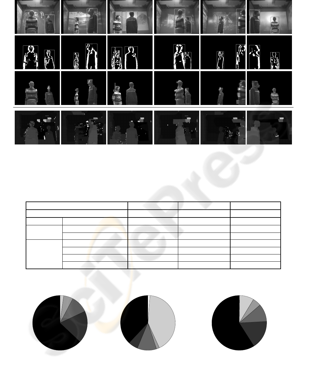
Figure 10: Samples of multi-object segmentation in the presence of fast lighting and texture changes. Top row: original im-
ages after undistortion and rectification, with bounding boxes indicating segmentation results. Second row: contour grouping
results. Third row: objects segmented from the scene. Last row: comparison with scene disparity map by graph cut (Kol-
mogorov, 2003).
Table 1: Object location accuracy with respect to the number of total objects.
no occlusion partial occlusion all objects
total true objects 1767 100.00% 334 100.00% 2101 100.00%
accurate exact bounding box 1113 62.99% 127 38.02% 1240 59.02%
inaccurate
enlarged bounding box 335 18.96% 19 5.69% 354 16.85%
partial object 182 10.30% 38 11.38% 220 10.47%
incorrect
enlarged partial object 99 5.60% 6 1.80% 105 5.00%
coalesced object 38 2.15% 140 41.92% 178 8.47%
object undetected 0 0.00% 4 1.20% 4 0.19%
false object 294 13.99%
exact
enlarged
partial
enlarged partial
coalescing
undetected
exact
enlarged
partial
enlarged partial
coalescing
undetected
exact
enlarged
partial
enlarged partial
coalescing
undetected
(a) no occlusion (b) partial occlusion (c) all objects
Figure 11: Object location accuracy with respect to the number of total objects.

5 CONCLUSION
A new disparity contour grouping method to iso-
late and distinguish multiple foreground objects in a
scene with fast illumination and texture change is pre-
sented. Without requiring full stereo reconstruction
or tedious empirical parameter tuning, the method
achieves near-real-time performance in software and
generates not only the 2D image locations of objects
but also boundaries and disparity information, pro-
viding a natural extension to 3D processing. As no
assumption is made on the shapes and textures of ob-
jects and environment, the proposed approach suits
generic object segmentation tasks.
ACKNOWLEDGEMENTS
The authors thank Jianfeng Yin for his help with
room geometry measurement and video acquisition
and Jeremy R. Cooperstock for providing essential re-
search facilities.
REFERENCES
Ayer, S. and Sawhney, H. S. (1995). Layered representation
of motion video using robust maximum-likelihood es-
timation of mixture models and MDL encoding. In
Int’l Conf. on Computer Vision, pages 777–784.
Cucchiara, R., Grana, C., Piccardi, M., and Prati, A. (2003).
Detecting moving objects, ghosts and shadows in
video streams. IEEE Trans. Pattern Analysis and Ma-
chine Intelligence, 25(10):1337–1342.
Elder, J. H. and Goldberg, R. M. (2002). Ecological statis-
tics of Gestalt laws for the perceptual organization of
contours. Journal of Vision, 2:324–353.
Elder, J. H., Krupnik, A., and Johnston, L. A. (2003). Con-
tour grouping with prior models. IEEE Trans. Pattern
Analysis and Machine Intelligence, 25(25):1–14.
Foley, J. D., van Dam, A., Feiner, S. K., and Hughes, J. F.
(1997). Computer Graphics: Principles and Practice
in C. Addison-Wesley, 2 edition.
Fusiello, A., Trucco, E., and Verri, A. (2000). A compact
algorithm for rectification of stereo pairs. Machine
Vision and Applications, 12(1):16–22.
Ivanov, Y., Bobick, A., and Liu, J. (2000). Fast lighting
independent background subtraction. Int’l Journal of
Computer Vision, 37(2):199–207.
Jepson, A. D. and Black, M. J. (1993). Mixture models
for optical flow computation. In Computer Vision and
Pattern Recognition, pages 760–761.
Kolmogorov, V. (2001-2003). Software.
http:
//www.adastral.ucl.ac.uk/
˜
vladkolm/
software.html
.
Kolmogorov, V., Criminisi, A., Blake, A., Cross, G., and
Rother, C. (2005). Bi-layer segmentation of binocular
stereo video. In Computer Vision and Pattern Recog-
nition, pages 407–414.
Kolmogorov, V. and Zabih, R. (2002). Multi-camera scene
reconstruction via graph cuts. In European Conf. on
Computer Vision, pages 82–96.
Lin, M. H. and Tomasi, C. (2004). Surfaces with occlusions
from layered stereo. IEEE Trans. Pattern Analysis and
Machine Intelligence, 26(8):1073–1078.
Narayanan, P. J., Rander, P. W., and Kanade, T. (1998).
Constructing virtual worlds using dense stereo. In
Int’l Conf. on Computer Vision, pages 3–10.
Oliver, N. M., Rosario, B., and Pentland, A. P. (2000). A
Bayesian computer vision system for modeling human
interactions. IEEE Trans. Pattern Analysis and Ma-
chine Intelligence, 22(8):831–843.
Rittscher, J., Kato, J., Joga, S., and Blake, A. (2000). A
probabilistic background model for tracking. In Euro-
pean Conf. on Computer Vision, pages 336–350.
Stauffer, C. and Grimson, W. (1999). Adaptive background
mixture models for real-time tracking. In Computer
Vision and Pattern Recognition, pages 246–252.
Sun, J., Zheng, N.-N., and Shum, H.-Y. (2003). Stereo
matching using belief propagation. IEEE Trans. Pat-
tern Analysis and Machine Intelligence, 25(7):787–
800.
Sun, W. and Cooperstock, J. R. (2006). An empirical eval-
uation of factors influencing camera calibration accu-
racy using three publicly available techniques. Ma-
chine Vision and Applications, 17(1):51–67.
Torr, P. H., Szeliski, R., and Anandan, P. (2001). An in-
tegrated Bayesian approach to layer extraction from
image sequences. IEEE Trans. Pattern Analysis and
Machine Intelligence, 23(3):297–303.
Toyama, K., Krumm, J., Brumitt, B., and Meyers, B.
(1999). Wallflower: principles and practice of back-
ground maintenance. In Int’l Conf. on Computer Vi-
sion, pages 255–261.
Wang, J. Y. and Adelson, E. H. (1993). Layered represen-
tation for motion analysis. In Computer Vision and
Pattern Recognition, pages 361–366.
Weiss, Y. and Adelson, E. H. (1996). A unified mix-
ture framework for motion segmentation: incorporat-
ing spatial coherence and estimating the number of
models. In Computer Vision and Pattern Recognition,
pages 321–326.
Wren, C. R., Azarbayejani, A. J., Darrell, T. J., and Pent-
land, A. P. (1997). Pfinder: real-time tracking of the
human body. IEEE Trans. Pattern Analysis and Ma-
chine Intelligence, 19(7):780–785.
Zhang, L., Curless, B., and Seitz, S. M. (2002). Rapid shape
acquisition using color structured light and multi-
pass dynamic programming. In Int’l Symposium on
3D Data Processing Visualization and Transmission,
pages 24–36.
