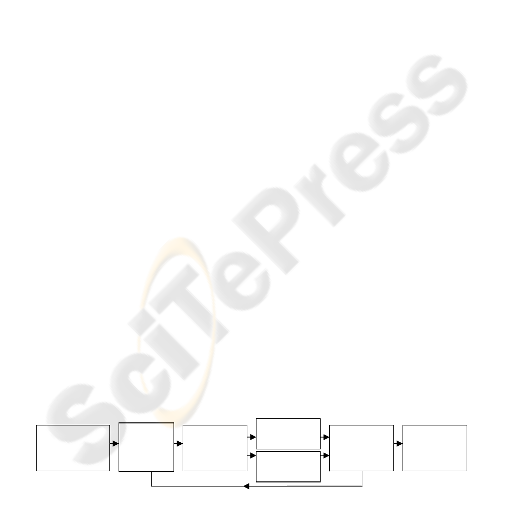
Figure 1: The block diagram of Intelligent Vision Agent System.
Image
Information
Intelligent
Agent
Spatial 3D
Model
Vision
Information
Sensing
and
Control
Space, Object
and Camera
Constraints
Desired
3D
Information
PLANNING OF A MULTI STEREO VISUAL SENSOR SYSTEM
FOR A HUMAN ACTIVITIES SPACE
Jiandan Chen, Siamak Khatibi and Wlodek Kulesza
The University of Kalmar, Norra Vagen 47, Kalmar, Sweden
Keywords: Sensor Placement, Multi Stereo View.
Abstract: The paper presents a method for planning the position of multiple stereo sensors in an indoor environment.
This is a component of an Intelligent Vision Agent System. We propose a new approach to optimize the
multiple stereo visual sensor configurations in 3D space in order to get efficient visibility for surveillance,
tracking and 3D reconstruction. The paper introduces a constraints method for modelling a Field of View in
spherical coordinates, a tetrahedron model for target objects, and a stereo view constraint for the baseline of
paired cameras. The constraints were analyzed and the minimum amount of stereo pairs necessary to cover
the entire target space was optimized by an integer linear programming. The 3D simulations for human
body and activities space coverage in Matlab illustrate the problem.
1 INTRODUCTION
Vision is one of the most important information
sources for humans. Human senses and the ability to
process this information may be extended by the use
of advanced technologies. The Intelligent Vision
Agent System, IVAS, is such a high-performance
autonomous distributed vision and information
processing system. It consists of multiple sensors for
gathering information and surveillance but also
control of these sensors including their deployment
and autonomous servo. It is able to extract 3D model
information from a real scene of target objects, and
compare this with a pattern in order to make
decisions. Meanwhile the patterns are also renewed
by the inclusion of a learning phase. These features
enable the system to dynamically adjust camera
configurations to track, recognize and analyze the
objects, to achieve the desired 3D information. The
Intelligent Agent consists of a knowledge database,
with learning and decision making components.
Figure 1 shows the block diagram working sequence
of the IVAS. The paper focuses on the planning of
stereo pair deployment of the system.
The critical problem for the system is to find the
optimal configuration of sensors so that the features
of the environment and target objects are visible
under the required constraints. The sensors’ intrinsic
and extrinsic parameters are examples of parameters
considered while choosing the configuration. The
system also requires optimal configuration for stereo
pair design.
1.1 Related Works
The sensor planning can be viewed as an extension
to the well-known Art Gallery Problem, AGP,
(O’Rourke, 1987). In its simplest form, the AGP
describes a simple polygon, often with holes, and the
task is to calculate the minimum number of guards
necessary to cover the entire polygon. Sensor
planning has a similar goal, to minimize the number
480
Chen J., Khatibi S. and Kulesza W. (2007).
PLANNING OF A MULTI STEREO VISUAL SENSOR SYSTEM FOR A HUMAN ACTIVITIES SPACE.
In Proceedings of the Second International Conference on Computer Vision Theory and Applications - IU/MTSV, pages 480-485
Copyright
c
SciTePress

of sensors needed to cover the target space. The
AGP has a Field of View, FoV, of 360° for the
guards, whereas in sensor planning the camera’s
FoV is limited by image resolution and the viewable
angles of cameras. A stereo view requires the target
space to be covered by at least two views.
Camera placement algorithms based on binary
optimization techniques are known, and analyzed for
camera deployment in a polygonal space in 2D
space (Erdem&Sclaroff, 2006). Also a linear
programming method to optimize sensor placement,
with respect to coverage, has been developed
(Hörster&Lienhart, 2006; Chakrabarty et al., 2002).
Using the sensor detection range r to solve the area
of grid coverage problem is common (Hörster
&Lienhart, 2006; Chakrabarty et al., 2002; Zou
&Chakrabarty, 2004). A quality metric including a
probabilistic occlusion can be used to evaluate the
optimum configurations of multiple cameras (Chen,
2002). The sensor planning can be analyzed by
examining the visibility in the dynamical
environment, and the result simulated by re-
annealing software (Mittal, 2006). An optimal stereo
vision configuration for a mobile robot focuses on
optimizing the stereo pair orientation to detect static
obstacles where the stereo pair is assumed to be
known a priori (Huang&Krotkov, 1997). For a
model-based sensor placement, the target geometry
information is known (Fleishman et al., 2000;
Chen&Li, 2004). Mobile single camera positioning
to optimize the observability of human activity has
been studied (Bodor et al., 2005). There has been
relatively little work on determining optimal
multiple sensors for sensor configurations
(Mittal, 2006).
2 PROBLEM FORMULATION
The algorithm proposed in the paper works in 3D
space and a new approach to define the camera’s
FoV, applied in spherical coordinates, is proposed.
In the presented solution the maximum volume of
FoV coverage becomes a part of sphere that
simplifies the calculation. The definition is
intrinsically related to the sensor’s physical
parameters, such as the dimension of the CCD and
focus length. For the camera’s view, this paper
considers not only the problem of coverage, but also
the orientation of the target. To deal with this, a
target space is modelled by a tetrahedron. The
presented method formulates all factors into the
constraints, and has a flexible way to add other
constraints. Knowledge of stereo technology is
integrated, a greedy stereo pair search algorithm
solving for the minimal amount of stereo pairs by
Integer Linear Programming, ILP, is proposed and
the ILP model is given.
2.1 Problem Statement and Main
Contributions
The paper addresses the problem of determining the
optimum amount of cameras and corresponding
positions and poses to observe human body and
activities space in stereo views.
The main contributions of the paper may be
summarised as follow:
• The new approach to modelling a 3D FoV using
spherical coordinates;
• Modelling of human and target space as
tetrahedrons;
• Stereo pairs formulation by a greedy algorithm
using stereo constraints;
• Minimizing the amount of stereo pairs by means
of the stereo view integer linear programming
model.
2.2 Definitions and Constraints
The space denotes a 3D indoor environment. The
target object or space describes the space for human
body and activities, and is required to be covered by
cameras’ FoVs. In other words, it should be visible
to the cameras and respect the minimal requirements
of each constraint. The constraints analysis ensures
sufficient data of scene features for 3D
reconstruction and image analysis. Design of the
optimal parameters for cameras’ positions, poses and
stereo baseline length is done according to the
criteria from cameras’ FoVs; the target objects and
stereo matching.
The following factors formulate the constraints:
Field of View is the maximal space volume visible
from a camera. The FoV is a cone determined by the
azimuth and elevation within a spherical coordinate
system.
Image Resolution, IR, describes the visibility of the
object in a camera view as the size of the object in
the image. IR is affected by the distance from
camera to the target object and the angle between the
camera view direction and the orientation of the
target objects surface.
Stereo Baseline Length is the distance between the
paired cameras in a stereo view. Stereo matching
becomes harder when the baseline length increases.
PLANNING OF A MULTI STEREO VISUAL SENSOR SYSTEM FOR A HUMAN ACTIVITIES SPACE
481
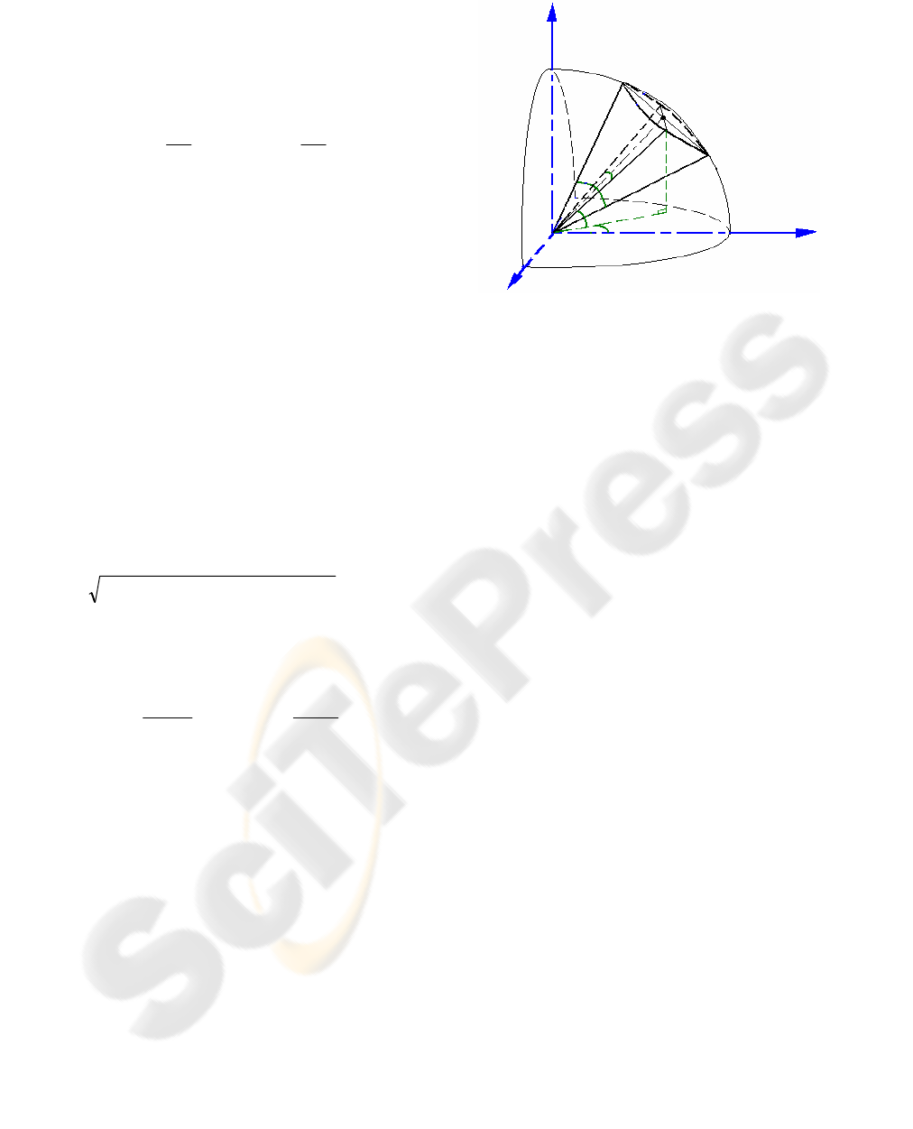
Figure 2: The spherical coordinates system and FoV of a
camera.
z
y
x
h
φ
v
φ
C
r
α
c
β
c
2.2.1 Camera Constraints
The horizontal and vertical viewable angles of the
camera can be determined by the focal length of the
lens and the size of the CCD element:
f
S
h
h
2
arctan2=
φ
,
f
S
v
v
2
arctan2=
φ
(1)
where
φ
h
and
φ
v
define the horizontal and vertical
viewable angles of the camera FoV; S
h
, S
v
are the
horizontal and vertical dimensions of the CCD
element, and f is the focal length of the lens.
The camera working distance, r, is the radius of
a sphere and can be calculated from the focal length
of the lens f and image resolution requirement.
The camera position C(x
c
,y
c
,z
c
) and pose
ψ
(
α
c
,
β
c
) describe the camera’s extrinsic parameters.
The camera pose defines its azimuth
α
c
and
elevation
β
c
.
In the world frame, the target object and
camera’s position and pose are described in
Cartesian coordinates. In the camera view, a
spherical coordinate system is applied. The distance
l between the target position O(x,y,z) and camera
position C(x
c
,y
c
,z
c
) is:
222
)()()(
ccc
zzyyxxl −+−+−=
(2)
The azimuth
α
o
and elevation
β
o
of target object
with respect to camera position are given by
c
c
o
yy
xx
−
−
= arctan
α
,
l
zz
c
o
−
= arcsin
β
(3)
In order for the target object feature point to be
covered by the camera’s FoV, the following
constraints must be fulfilled:
rl ≤
and
2/2/
hcohc
φ
α
α
φ
α
+≤≤−
2/2/
vcovc
φ
β
β
φ
β
+≤≤−
(4)
In the spherical coordinate systems, the range of
the camera’s FoV is directly determined by
S
h
, S
v
,
r
and f, which makes it easy to dynamically compute
FoV according to the changing of the focal length
f.
The modelling of the FoV can be viewed as a part of
the sphere, as shown in Figure 2.
2.2.2 Object Constraints
In the human living environment, we always have
some knowledge about the target objects and space
under observation, e.g. the floor plan of the room,
the geometric properties of the furniture, human
body and activities space, etc.
The 3D target object or space can be modelled
by a tetrahedron, giving four triangles. We define
four vertices of tetrahedron by
Tv
1,2,3,4
, as in
Figure 3. The three upward triangles are required to
be covered by cameras’ FoVs. The normal of each
triangle gives the orientation of the surface.
If the
visibility angle
θ
, between the triangle normal n
G
and a line drawn from the centroid of triangle to
camera position increases then the image resolution
decreases. In order to get good image resolution, an
angle
θ
less than the maximum visibility angle
θ
max
is required:
max
θ
θ
≤
(5)
It is best that the camera orientation
c
G
lines up
with the centroid of triangle, bringing the target
object to the centre of the camera’s FoV and causing
less lens distortion. The angle between camera
orientation
c
G
and a line drawn from camera position
to the centroid of triangle less than the maximum
ϕ
max
is also required and constrained as:
max
ϕ
ϕ
≤
(6)
The triangle is considered to be covered if all
three vertices are within a camera’s FoV and fulfil
constraints (5) and (6), guaranteeing good
observability of the target object.
VISAPP 2007 - International Conference on Computer Vision Theory and Applications
482
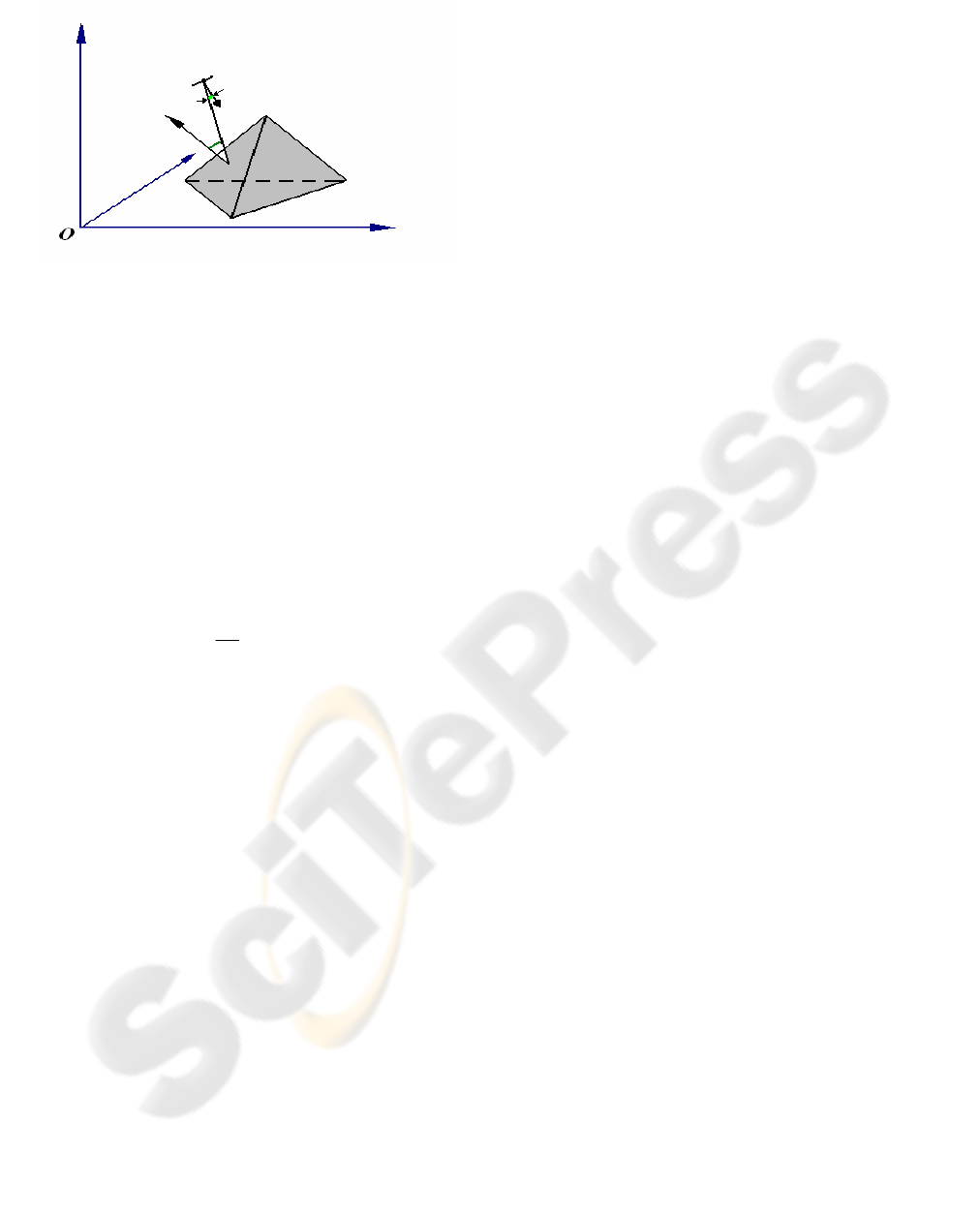
Figure 3: Illustration of the human space modelled as
a
tetrahedron;
θ
- the visibility angle between triangle normal
n
G
and a line from the centroid of the triangle to camera
position;
ϕ
- the angle between camera orientation c
G
and a
line from the camera position to centroid of the triangle.
T
v
2
T
v
3
T
v
1
T
v
4
z
y
C
n
G
c
G
ϕ
θ
x
2.2.3 Stereo Pair Constraints
We construct the stereo coverage from the overlap
of two cameras’ FoVs. Overlapping FoVs are
typically used in computer vision for the purpose of
extracting 3D information (Khan
et al., 2001). The
area of stereo coverage must cover all of the target
objects. Assuming the camera is a pinhole camera,
the 3D depth
Z
is given by (Faugeras, 1993):
dx
Bf
Z =
(7)
where
B is the baseline length between two cameras
and
dx is the disparity.
The accuracy of depth resolution relies on stereo
matching, but stereo matching becomes harder as the
baseline length increases. Hence, we have a
constraint defining the maximum baseline length for
stereo matching:
max
BB ≤
(8)
3 APPROACHES
The stereo pair placement problem consists of two
stages. Firstly, we find potential stereo pairs that
satisfy stereo constraint by greedy searching from all
potential cameras’ positions and poses. Secondly,
we minimize the amount of stereo pairs needed,
subject to the coverage constraint.
3.1 Greedy Algorithm
The algorithm gives a flexible way to organize
cameras into stereo pairs, each potential camera to
be included in a stereo pair may be chosen by an
algorithm according to the stereo pair constraint.
The first step of the algorithm is to sample the
potential camera’s positions
C
n
(x
cn
,y
cn
,z
cn
) and poses
ψ
n
(
α
cn
,
β
cn
) of the camera state, ,
,
k
C
nn
Scamera
ψ
where
k is camera state index number. The target object,
which we must cover, is modelled as a tetrahedron.
In the next step, we compute all of the potential
cameras’ positions and poses needed to cover each
upward triangle of this model. Taking this, we
combine every two camera states to be a potential
stereo pair,
Stereopair
i
, according to the stereo
constraint (8). The algorithm is sufficiently flexible
to add other constraints for stereo pairs, e.g. the
angle constraint between the cameras’ optical axes.
Finally the algorithm removes the redundant
potential stereo pairs.
3.2 Stereo View Integer Linear
Programming Model
This model assumes that one type of camera is used
throughout, resulting in just one camera’s FoV being
considered. The optimization of the amount of
cameras with different FoVs also can be easily
extended, by adding one more term for different
FoVs. Since the stereo pairs have been found by the
greedy algorithm, the integer linear programming
can be applied to minimize the total stereo pairs
subject to the coverage constraint (Hörster
&Lienhart, 2006; Chakrabarty et al., 2002).
A binary variable is computed and stored in
advance. The stereo visibility binary variable table
Stereovis
j,i
is defined by:
otherwise
modelobject target of e triangl
covers a if
0
1
,
j
Stereopair
Stereovis
i
ij
⎪
⎩
⎪
⎨
⎧
=
(9)
which indicates each triangle
j as the row j to be
covered by the stereo pair
i in the column i, and
s
Ki
≤
≤
1 , where K
s
is the total number of stereo
pairs.
This objective function minimizes the number of
stereo pairs needed to cover all triangles in the target
object model, and also ensures that the target object
is covered by at least one stereo pair:
PLANNING OF A MULTI STEREO VISUAL SENSOR SYSTEM FOR A HUMAN ACTIVITIES SPACE
483
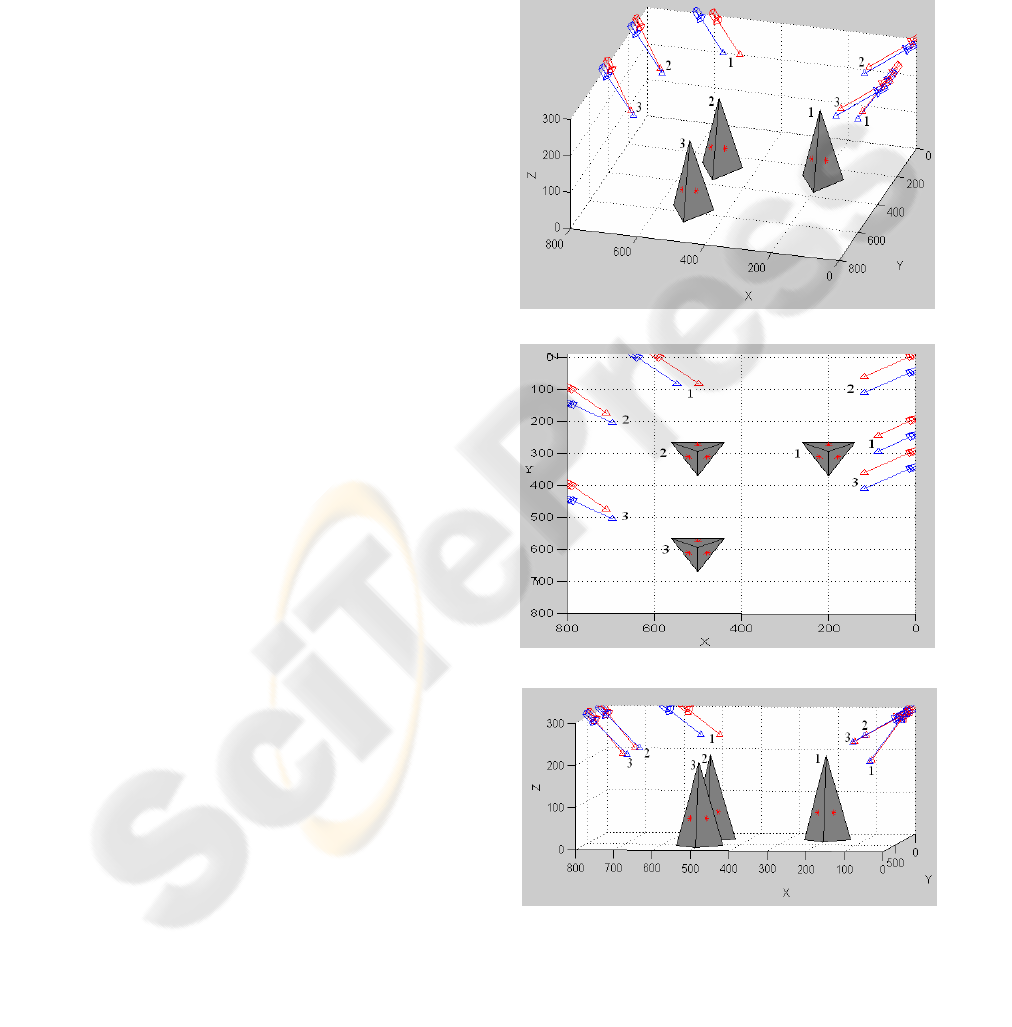
Figure 4: The human space modelled as tetrahedron with
corresponding cameras’ positions and poses changing
according to the model location; (a) perspective view (b)
top view (c) side view.
(
a
)
(
c
)
(
b
)
∑
=
s
K
i
i
S
1
min
(10)
subject to
1
,
1
≥×
∑
=
ij
K
i
i
StereovisS
s
, 32,1,for =j
(11)
where the
S
i
is the binary variable where a “1”
indicates the stereo pair to be chosen.
To ensure that only one camera is located at
each position and has only one pose, the conflict
binary variable table
c
p,i
is also calculated in advance
and defined by:
for
i=1, 2,
…
, K
s
, and p=1, 2,
…
, K
s.
One more constraint is added into the model:
1
,
1
≤×
∑
=
ip
K
i
i
cS
s
,
s
K,, p ,21 for ⋅⋅⋅=
(13)
The information on the optimal number of stereo
pairs, and which pairs to use, are returned as vectors
by the ILP model.
4 RESULTS
The described algorithm was simulated in MATLAB
7.0. The integer linear programs lpsove package
(Berkelaar et al., 2005) and the Epipolar Geometry
Toolbox (Mariottini&Prattichizzo, 2005) were used
to minimise the amount of cameras and transform
the object position in 3D separately. The simulation
environment considers a rectangular room with size
8x8x3 m. The modelling of the human body as a
tetrahedron requires three upward triangles; each of
them occludes the triangles behind it and must be
visible to at least one pair of cameras. The human
model is 2 m high and 1.2 m at the base edges. The
cameras’ positions are restricted to the ceiling
around the room, their potential positions sampled at
half meter intervals, and the poses sampled at 12°
intervals. The camera has same horizontal and
vertical viewable angles
φ
h
,
φ
v
of 60° and has a
working distance
r
of 7 m. The maximum visibility
angle
θ
max
and the angle
ϕ
max
are taken to be 70° and
10° respectively. The maximum stereo baseline
length B
max
is 1.5 m.
This case study illustrates the optimum amount
of stereo pairs with corresponding cameras’
positions and poses changing according to the model
location. In order to clearly show cameras’ positions
and poses, the analysis only considers the model at
otherwise
wherens, orientatio
different with camera same
theshare and pairs twoif
0
1
,
pi
pi
c
ip
≠
⎪
⎪
⎩
⎪
⎪
⎨
⎧
=
(12)
VISAPP 2007 - International Conference on Computer Vision Theory and Applications
484

three locations 1, 2 and 3, see Figure 4. The arrows
indicate the optical axes of the cameras. The index
numbers indicate the model locations and
corresponding cameras’ positions and poses. In each
position every upward triangle surface is visible to at
least one stereo pair; the algorithm proves that a set
of two pairs is sufficient to cover three triangle
surfaces. When the model moves from position 1 to
position 2, the stereo pair positions (0,200) and
(0,250) change to (0,0) and (0,50) respectively. The
elevation angle is increased as the model moves
further away from the camera. At the same time,
another stereo pair located at (600,0) and (650,0)
moves to (800,100) and (800,150) respectively, the
elevation angle is decreased as the model moves
closer to it. The azimuth
α
c
and elevation
β
c
in
stereo pair may vary by camera individually. Both
two stereo pairs follow the model when the model
changes from position 2 to position 3, see Figure 4.
5 CONCLUSION
The proposed approach is useful in determining the
optimal number of cameras and their corresponding
positions and poses to observe human body and
activities space in stereo view. The stereo pair has
the flexibility to adjust cameras’ poses and positions
individually. Multi camera planning and control for
surveillance and tracking in supermarkets, museums
and the home environment, and especially in
situations which require stereo data to reconstruct
3D, are possible fields of application.
To model the target object as a tetrahedron
gives a convenient way to extract the orientation of
each surface and guarantee a good observability.
Modelling camera’s FoV using spherical coordinates
simplifies the model and constraints, which speeds
up computations. Formulating the stereo pairs with
greedy algorithm using stereo constraints is a simple
way to get all possible stereo pairs and then
minimize the amount of stereo pairs by means of the
stereo view ILP model.
It is possible to extend this algorithm to
dynamic cameras to track humans. In order to follow
target objects movement, the camera movement
distance constraints can be applied (Chen et
al., 2007). The human activities space also can be
extended to a large space modelled by multiple
tetrahedrons. The space can be covered without
changes of cameras’ positions and poses. Future
work may focus on dynamic occlusions and tracking
multiple dynamic objects by using multiple dynamic
stereo pairs.
REFERENCES
Berkelaar, M., Notebaert, P., and Eikland, K., 2005,
Lpsolve 5.5: Open Source (mixed-integer) Linear
Programming System. Eindhoven Univ. of
Technology,
http://tech.groups.yahoo.com/group/lp_solve/files/.
Bodor, R., Drenner, A., Janssen, M., Schrater, P.,
Papanikolopoulos, N., 2005, Mobile Camera
Positioning to Optimize the Observability of Human
activity Recognition Task. Intelligent Robots and
Systems, IEEE/RSJ Int. Conf.
Chakrabarty, K., Iyengar, S. S. , Qi, H., and Cho., E.,
2002, Grid Coverage for Surveillance and Target
Location in Distributed Sensor Networks.
IEEE
Transaction on Computers
, 51(12): 1448-1453.
Chen, J., Khatibi, S., Kulesza, W., 2007, Planning of A
Multi Stereo Visual Sensor System Depth Accuracy
and Variable Baseline Approach. Submitted to
3DTV-
Conference
, Greece.
Chen, S. Y., Li Y. F., 2004, Automatic Sensor Placement
for Model-Based Robot Vision. IEEE Transactions on
Systems, Man, and Cybernetics VOL.34, No.1
.
Chen, X., 2002, Design of Many-Camera Tracking
Systems for Scalability and Efficient Resource
Allocation. PhD thesis, Stanford University.
Erdem, U., Sclaroff, S., 2006, Automated Camera Layout
to Satisfy Task-Specific and Floor Plan-Specific
Coverage Requirements. Computer Vision and Image
Understanding
103, 156-169.
Faugeras, O., 1993,
Three-dimensional computer vision.
MIT Press.
Fleishman, S., Cohen-Or, D., and Lischinski, D., 2000,
Automatic Camera Placement for Image-based
modelling. Computer Graphics Forum, 19(2):101-110.
Huang, W. H. , Krotkov, E. P., 1997,
Optimal Stereo
Mast Configuration for Mobile Robots.
Processing of
IEEE Int. Conf. Robotics.
Hörster, E., Lienhart, R., 2006, On the Optimal Placement
of Multiple Visual Sensors,
ACM International
Workshop on Video Surveillance & Sensor Networks
.
Khan, S., Javed, O., Rasheed, Z., Shah, M., 2001, Human
Tracking in Multiple Cameras. The Eighth IEEE Int.
Conf. On Computer Vision.
Mariottini, G. L., Prattichizzo, D., 2005, The Epipolar
Geometry Toolbox: Multiple View Geometry and
Visual Servoing for Matlab
. Robotics and
Automation,Proceedings of the IEEE Int. Conf
.
Mittal, A., 2006, Generalized Multi-Sensor Planning
. 9th
European Conference on Computer Vision (ECCV).
O’Rourke, J.,1987
Art Gallery Theorems and Algorithms.
Oxford University Press.
Zou, Y. and Chakrabarty, K., 2004, Sensor Deployment
and Target Localization in Distributed Sensor
Network. Trans. On Embedded Computing Sys.,
3(1):61-91.
PLANNING OF A MULTI STEREO VISUAL SENSOR SYSTEM FOR A HUMAN ACTIVITIES SPACE
485
