
DETECTION AND TRACKING OF
MULTIPLE MOVING OBJECTS IN VIDEO
Wei Huang and Jonathan Wu
Department of Electrical and Computer Engineering, University of Windsor
Windsor, Ontario, N9B 3P4, Canada
Keywords: Motion detection, tracking, partial occlusion, color, texture, DCT, inexact graph matching.
Abstract: This paper presents a method for detecting and tracking multiple moving objects in both outdoor and indoor
environments. The proposed method measures the change of a combined color-texture feature vector in each
image block to detect moving objects. The texture feature is extracted from DCT frequency domain. An
attributed relational graph (ARG) is used to represent each object, in which vertices are associated to an
object’s sub-regions and edges represent spatial relations among the sub-regions. Object tracking and
identification are accomplished by matching the input graph to the model graph. The notion of inexact graph
matching enables us to track partially occluded objects. The experimental results prove the efficiency of the
proposed method.
1 INTRODUCTION
The efficient detection and tracking of multiple
moving objects is currently one of the most active
research topics in computer vision. It has many
applications such as visual surveillance, human-
machine interfaces, video communication, and so
on.
As for motion detection, the background
subtraction technique is a popular method. In
(
Stauffer and Grimson, 2000), the pixel value was
modeled by a mixture of weighted K Gaussian
distributions to support multiple backgrounds.
(
Elgammal et al., 2002) used a nonparametric kernel
density model by estimating the probability of pixel
intensity directly from a set of recent intensity
values.
As to the tracking method, the most widely used
cues in object tracking are color, spatial position,
shape and motion. In (
Xu et al., 2004), five significant
features were used, including velocity, size, elliptic-
fit aspect ratio, orientation, and dominant color.
(
Brasnett et al., 2005) demonstrated that the combined
color and texture cues provided a good tracking
result that was more accurate than the two cues
individually.
In this paper we introduce a new motion
detection method which does not compute any
model of the background. We measure the change of
a combined color-texture feature vector in each
image block within a time window and then directly
obtain moving objects by statistically analyzing the
change. For effective tracking, the attributed
relational graph is used to represent each moving
object. A combined color-texture-position feature
vector is used to describe each object’s sub-regions,
which are associated to the vertices of the ARG.
Inexact graph matching enables us to track and
identify partially occluded objects. In the discussion
below, we calculate the color-texture combined
feature vector for motion detection in Section 2.1,
and then we explain the details of detecting moving
objects using eigenspace decomposition and
statistical analysis in Section 2.2. Section 2.3
describes how to construct the attributed relational
graph to represent the detected object. Section 2.4
gives the details of identifying objects using inexact
graph matching technique. We show experimental
results for real image sequences in Section 3.
Conclusions are given in Section 4.
2 PROPOSED ALGORITHM
2.1 The Color-Texture Feature
Approach for Motion Detection
In (Latecki et al., 2004), an idea was introduced that
the texture vectors are very likely to have a large
spread when a moving object is passing through a
492
Huang W. and Wu J. (2007).
DETECTION AND TRACKING OF MULTIPLE MOVING OBJECTS IN VIDEO.
In Proceedings of the Second International Conference on Computer Vision Theory and Applications - IU/MTSV, pages 492-497
Copyright
c
SciTePress

T
u
f
tu
f
S
St
u
f
tu
f
S
u
R
⎟
⎠
⎞
⎜
⎝
⎛
⎟
⎠
⎞
⎜
⎝
⎛
−
−
∑
+
−=
−
−
+
=
,,
12
1
,
τ
τ
τ
∑
=
=
L
u
u
C
L
1
,
1
ττ
μ
()
2
1
,
1
2
∑
=
−=
L
u
u
C
L
τ
μ
ττ
σ
fixed position. Motivated by this idea, we measure
the change of a combined color-texture feature
vector to detect moving objects. Combining color
and texture as the feature vector can still extract
foreground objects when the color distributions of
the foreground and background are similar, in which
case the Gaussian mixture model will fail. We
assume a stationary camera.
We use some DCT coefficients as the texture
feature. We partition every new frame into blocks
with 8 * 8 pixels, where every two neighboring
blocks overlap each other by four pixels horizontally
or vertically for improving the spatial resolutions of
the detection results. A feature vector is extracted for
each block. Eleven features are used for detection.
Two of them are the average color components
),(
Cr
A
Cb
A
in an 8 * 8 block. The other nine
features are the first nine AC coefficients inside each
block along the zigzag scanning. We use the well-
known
r
C
b
YC
color space, where Y encodes
luminance,
b
C
and
r
C
encode color information
(chrominance). To obtain the other nine features, the
DCT is applied to the Y component of the image
block. One color-texture feature vector for a block u
is then expressed as:
(1)
2.2 Detection of Moving Objects by
Measuring the Change of the
Color-Texture Feature Vector
By measuring the change of the color-texture feature
vector over time, we are able to detect whether a
particular block belongs to a background or to a
moving object. We compute the covariance matrix
of the feature vectors in the same block location
within a small number of consecutive frames. The
eigenvalues of the covariance matrix refer to the
variance of the data in the direction of the basis
vectors. We use the largest eigenvalue as a local
change measure. The larger the largest eigenvalue,
the more likely is the presence of a moving object.
In practice, for each block u, we consider the
color-texture feature vectors for a symmetric
window with size of 2S+1 around the temporal
instant
τ
:
SuSuuSu +−++−
τττττ
,,1,,1,
,...,,...,, fffff
S-u,
. S is set
to 1 here. For these vectors, the covariance matrix
τ
,u
R
is:
(2)
Then, the covariance matrix
τ
,u
R
is decomposed
into its eigenvectors
()
k
u
e
τ
,
and eigenvalues
(
)
k
u
τ
λ
,
( k =1, 2, …, 11).
(3)
The largest eigenvalue
m
u
τ
λ
,
is the local
change measure
.
,
τ
u
C
(4)
Finally, we mark each block as part of a moving
object or background according as whether the
change measure is larger than a predefined threshold
or not. We assume that the values of the local
change measure
τ
,u
C
in every video frame obey the
Gaussian distribution. We compute the mean
τ
μ
and
variance
2
τ
σ
of all
τ
,u
C
for u=1, 2,…, L. L is the
total number of sub blocks of every video frame. A
block will be labelled as moving if
(5)
Where th1 is a constant and is set to 0.5 here.
(6)
(7)
The pixels belonging to an object are connected.
A connected component analysis algorithm is used
to find connected components in the binary images
that we obtained at the motion detection stage. We
use a size filter to remove the connected component
whose area is below a threshold th2.
2.3 Object Representation by the
Attributed Relational Graph
Currently, color histogram is widely used to
represent detected objects (
Comaniciu et al., 2003).
However, color histograms have limited
discriminative power. Two images producing
()
T
AAAAAAAAA
Cr
A
Cb
A
1,4
,
2,3
,
3,2
,
4,1
,
1,3
,
2,2
,
3,1
,
1,2
,
2,1
,,=
tu,
f
)(
,
).(
,
)(
,
.
,
k
u
ek
u
k
u
e
u
R
ττ
λ
ττ
=
m
uu
C
τ
λ
τ
,,
=
(
)
1
2
2
,
th
u
C
>
−
τ
σ
τ
μ
τ
DETECTION AND TRACKING OF MULTIPLE MOVING OBJECTS IN VIDEO
493

identical color histograms may have totally different
spatial organization of colors. In this paper, we use
an attributed relational graph to represent each
object, in which vertices are associated to an object’s
sub-regions and edges represent spatial relations
among the sub-regions. Therefore, the tracking and
identification of objects amounts to graph matching.
Both input and model graphs are automatically
extracted from video sequences. Usually, the graphs
extracted in the first frame act as the model graphs.
To fragment an object into sub-regions, we first
use a combined color-texture-position feature vector
to describe the detected image blocks which belong
to the object. The two color features are the average
color components
),(
Cr
A
Cb
A
in an 8*8 image
block. The one texture feature is the average
summation of the first nine squared AC coefficients
along the zigzag scanning. The two position features
are simply the coordinates of the image block. After
obtaining the feature vectors for all the blocks, we
perform normalization on the five features to
eliminate the effects of different feature ranges.
Then the k-means algorithm is used to cluster the
feature vectors into several classes with every class
in the feature space corresponding to one spatial
sub-region of the detected object. The k-means
algorithm does not specify the value of k. To
compute the optimal value of k, we iterate it between
a minimum
()
2
min
=k and a maximum value
()
5
max
=k until a stop constraint is satisfied.
After the segmentation, we are ready to build the
ARG for each detected object. An ARG is a graph in
which attribute vectors are assigned to vertices and
to edges. Formally, we define an ARG as
()
νμ
,,, ENG = , where N represents the set of
vertices of G and
NNE x ⊆ the set of edges. Two
vertices a, b of N are said to be adjacent if
()
Eba ∈, . Furthermore,
N
LN →:
μ
assigns an
attribute vector to each vertex of G, while
E
LE →:
ν
assigns an attribute vector to each
edge in G.
The structure of an object can be represented as a
collection of sub-regions which are related by their
relative positions within the object. The sub-regions
are represented by vertices in a graph, while
relations between them are represented by edges. Let
us consider any two vertices a, b in N. The vertex
attribute
()
a
μ
is defined as follows:
()
(
)
T
y
P
x
P
AC
T
Cr
C
Cb
Ca ,,,,=
μ
(8)
The five terms correspond to the color
component
Cb
C , color component
Cr
C , texture
AC
T ,
spatial coordinate
x
P and spatial coordinate
y
P at the
centroid location of a cluster, respectively. Each
cluster obtained by k-means algorithm corresponds
to a sub-region within the object.
The edge attribute
(
)
ba,
ν
, for a, b, in E, is
defined as the length value of the edge linking the
two vertices a and b.
In practice, the object is represented by a
signature, which is composed of two parts: the first
one is the feature vectors of all sub-regions, which
are called vertex attributes, and the second one is a
representation of the topology of the sub-regions
within the object. Spatial relationships between sub-
regions are characterized by an adjacency matrix of
sub-regions with a value of 1 if both sub-regions
have at least one pixel in common, otherwise 0. For
the pair of adjacent sub-regions, the length value of
the corresponding edge is stored in a distance
matrix.
2.4 Inexact Graph Matching for
Tracking and Identification of
Moving Objects
When graphs are used to represent objects, the
problem of objects tracking and identification can be
seen as a problem of graph matching. The notion of
inexact graph matching enables us to track partially
occluded objects. Two matched graphs do not have
to be identical but only similar in terms of vertex
number, vertex attributes or edge number. Our
implementation of the matching algorithm is given
below:
In the following, a, b refer to vertices in the input
graph I, and
'
a ,
'
b correspond to vertices in the
model graph M.
1) For each vertex a in the input graph, a search is
conducted to find the best matching vertex
'
a in the
model graph, such that the Euclidian distance of the
matching vertex attributes
()
(
)
(
)
'
, aad
μμ
is the
minimum value. The vertex similarity for this pair of
vertices is computed as:
()
()()
'
'
, aad
aa
v
eS
μμ
−
= (9)
We have to satisfy two basic constraints during the
matching process:
2) A vertex in the input graph cannot match with
two different vertices in the model graph.
VISAPP 2007 - International Conference on Computer Vision Theory and Applications
494
3) Two different vertices in the input graph cannot
match with a single vertex in the model graph.
It is possible that some vertices in the input graph do
not have matching vertices in the model graph
because the two graphs may have different vertex
number.
4) After the vertices are matched, total similarity is
computed by taking into account the topology of the
matched graphs.
Let the vertices a and b match
'
a
and
'
b respectively. Then the topology similarity for this
pair of vertices is computed as:
''
''
ba
ab
eS
baba
e
νν
−−
= (10)
Where
ab
ν
and
''
ba
ν
are the length values of the
edges ab and
''
ba .
5) The total similarity for matching the input graph
to the model graph is given by
()
∑∑
−
+
∑
=
ab
baba
e
S
e
N
a
aa
v
S
s
N
MIS
''
1
'
,
1
αα
(11)
Where
s
N is the maximum vertex number
between the two matching graphs.
e
N is the
maximum number of really existing edges between
the two matching graphs. It is possible that edges in
the input graph do not have corresponding edges in
the model graph and vice-versa.
α
is a scaling
parameter which controls the relative importance of
the two similarity functions.
α
is set to 0.6 here.
6) The total similarity is then scaled to reflect the
difference in the size and position of the input and
model objects.
() ()
MISpmMIS ,
1
**, = (12)
If
i
m and
m
m denote the sizes of the input
object and model object respectively, then:
⎭
⎬
⎫
⎩
⎨
⎧
=
i
m
m
i
m
m
m
m
m ,min
(13)
otherwise e
d e
1-
0
dd-
0
⎪
⎩
⎪
⎨
⎧
<
=
d
p
14)
where d is the Euclidian distance between the
centroids of the input and model objects.
0
d is a
constant and set to 20 here. The motivation of
adding the position scaling factor p into the
similarity fuction is that an object will not move far
from its last position. Therefore, the centroid
presents us with a useful feature for tracking objects.
To let this factor work properly, we update the
model’s position once we get an input object
matched to that model.
7) The best candidate match
*
M
satisfies
(
)
()
MISMIS
M
,max,
*
=
(15)
When the value of
(
)
*
, MIS is more than a
predefined threshold, we say the input graph/object
is identified with the model graph/object. Otherwise,
we assume a new object enters the scene, it will be
tracked and labelled, and the corresponding ARG of
that object is constructed and stored in the model
graph/object list.
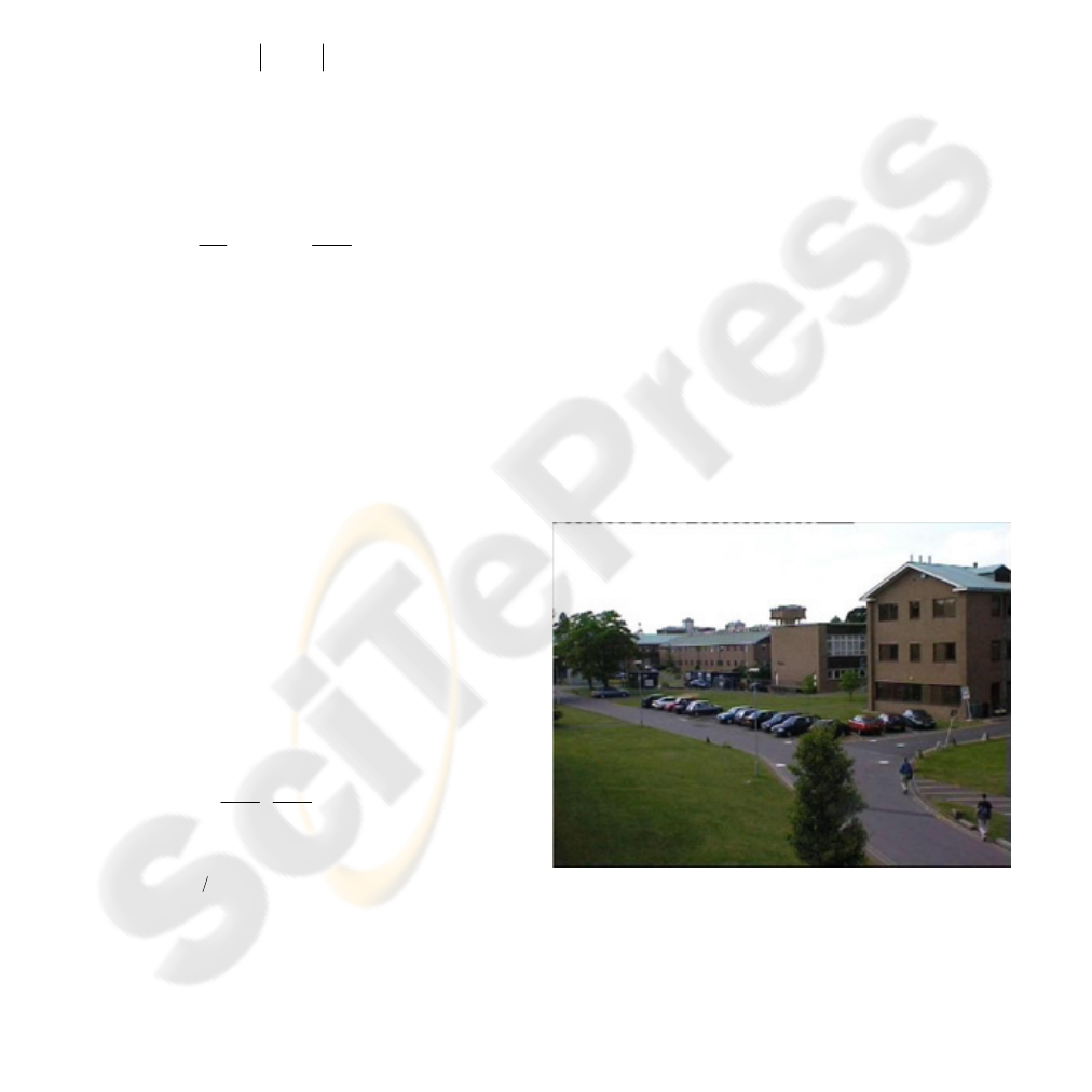
3 EXPERIMENTAL RESULTS
Our proposed method is tested on both outdoor and
indoor image sequences: PETS 2001 dataset 2 and
PETS 2006 S3-T7-A dataset. The image sizes of the
PETS 2001 and PETS 2006 datasets are 768*576
and 720*576, respectively. The PETS 2001 dataset
involves swaying trees. The PETS 2006 dataset
involves cast shadows. Results are shown in Fig. 1-
Fig. 4.
Figure 1: (a) Original image from PETS 2001 dataset 2.
DETECTION AND TRACKING OF MULTIPLE MOVING OBJECTS IN VIDEO
495
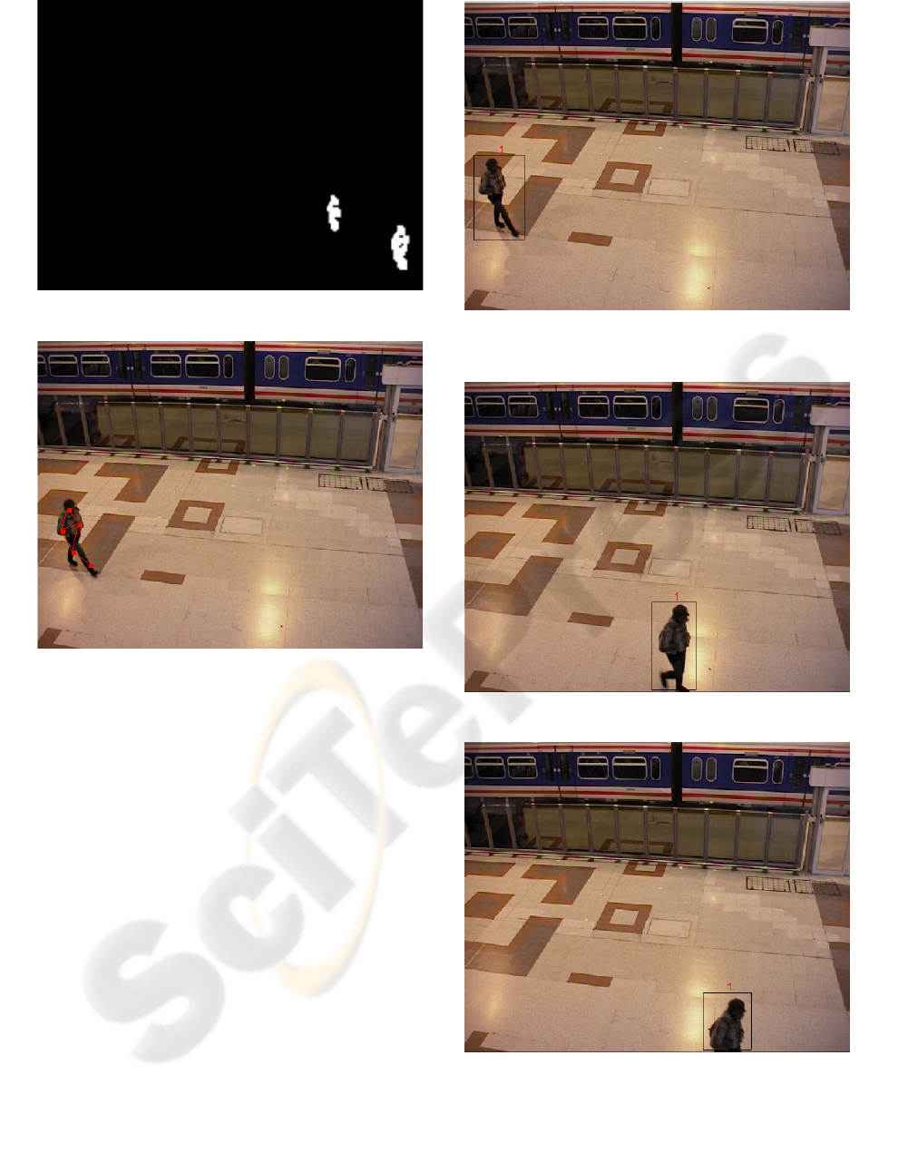
Figure 1: (b) Motion detection result.
Figure 2: Original image from PETS 2006 S3-T7-A
dataset with the attributed relational graph.
(a)
(b)
(c)
Figure 3: Tracking a single object in indoor environment.
VISAPP 2007 - International Conference on Computer Vision Theory and Applications
496
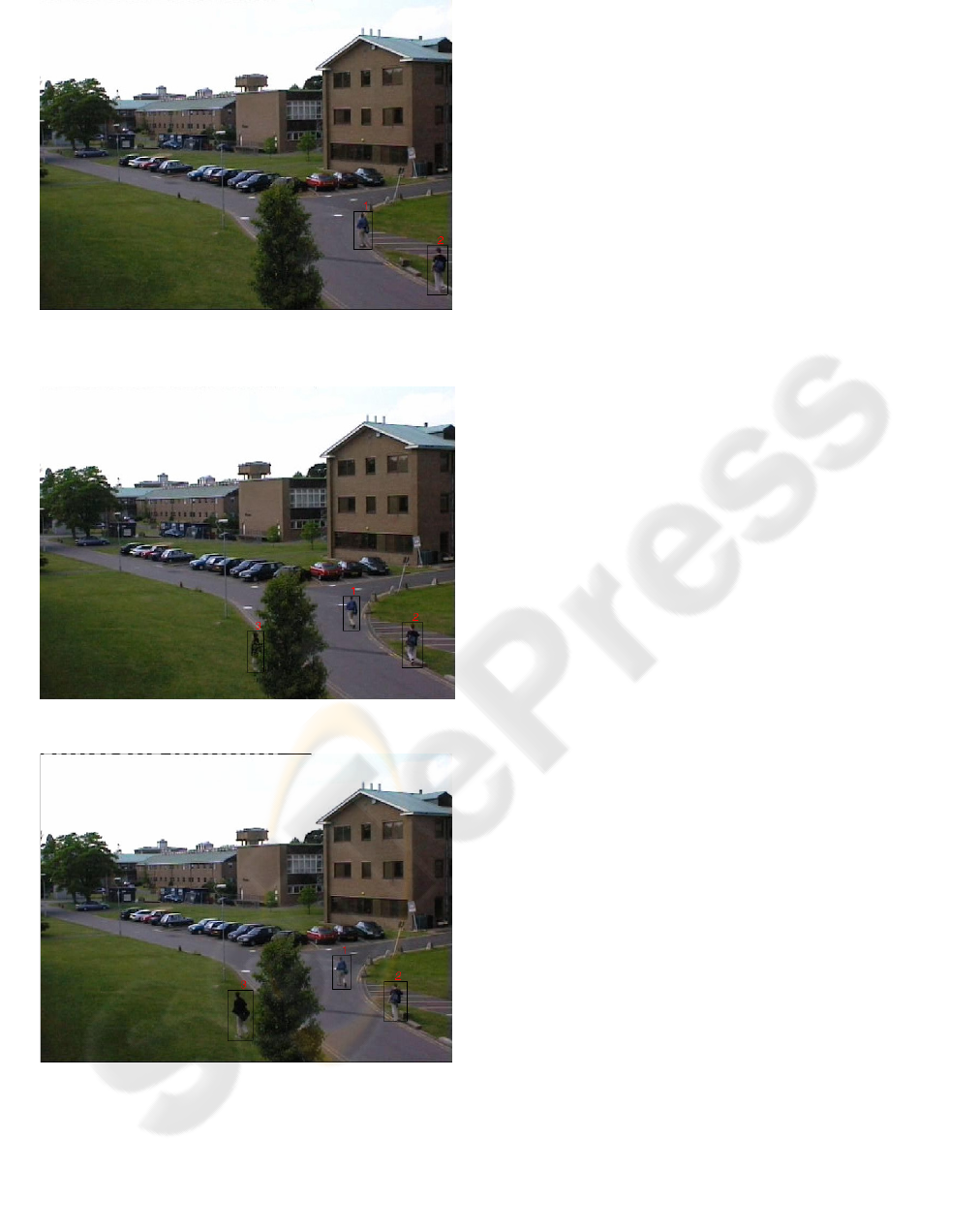
(a)
(b)
(c)
Figure 4: Tracking multiple moving objects in outdoor
environment with dynamic background.
4 CONCLUSIONS
In this paper, we propose a novel method for
detection and tracking multiple moving objects in
both outdoor and indoor environments. To detect the
moving objects, we compute a combined color-
texture feature vector for each image block and
measure the change of the color-texture feature
vector of the image block within a certain time
interval. For tracking and identification of the
detected multiple moving objects, we represent each
object by an ARG, in which vertices are associated
to an object’s sub-regions and edges represent
spatial relations among the sub-regions. The notion
of inexact graph matching enables us to track
partially occluded objects. The future work is to
solve the case when an object is totally occluded.
REFERENCES
Brasnett, P., Mihaylova, L. Canagarajah, N. and Bull, D.,
2005. Particle filtering with multiple cues for object
tracking in video sequences. Proc. of SPIE-IS&T
Electronic Imaging, vol. 5685, pp. 430-441.
Comaniciu,.D., Ramesh, V. and Meer, P., 2003. Kernel-
based object tracking. IEEE Trans. Pattern Analysis
and Machine Intelligence, vol. 25, no. 5, pp. 564-577.
Elgammal, A., Duraiswami, R., Harwood, D. and Davis,
L., 2002. Background and foreground modeling using
nonparametric kernel density estimation for visual
surveillance. Proceedings of the IEEE, vol. 90, no. 7,
pp. 1151-1163.
Latecki, L., Miezianko, R., and Pokrajac, D., 2004.
Motion detection based on local variation of
spatiotemporal texture. Proceedings of the 2004 IEEE
Computer Society Conference on Computer Vision
and Pattern Recognition Workshops (CVPRW’04), pp.
135-141.
Stauffer, C. and Grimson, W., 2000. Learning patterns of
activity using real-time tracking. IEEE Trans. Pattern
Analysis and Machine Intelligence, vol. 22, no. 8, pp.
747-757.
Xu, L., Landabaso, J. and Lei, B., 2004. Segmentation and
tracking of multiple moving objects for intelligent
video analysis. BT Technology Journal, vol. 22, no. 3,
pp. 140-150.
DETECTION AND TRACKING OF MULTIPLE MOVING OBJECTS IN VIDEO
497
