
EXPERIMENTAL STUDY FOR 3D RECONSTRUCTION BASED
ON ROTATIONAL STEREO
Xi-Qing Qi, S. Y. Chen, Sheng Liu and Jianwei Zhang
Department of Information Engineering, Zhejiang University of Technology, Hangzhou, China
Department of Informatics, University of Hamburg,Hamburg, Germany
Keywords: Rotational stereo, calibration, reconstruction, stereo vision.
Abstract: With a traditional stereo vision system, images of the object are acquired from different positions using two
cameras and the depth (distance) information is resumed from disparity. This costs a little high and is still
inconvenient to implement since the sensor needs to be moved by a manipulator to be around the object for
complete model construction. In this paper, a 3D reconstruction method based on rotational stereo is
proposed. The object to be reconstructed is placed on a rotational plate which can be precisely controlled by
a computer. Only one camera is needed to capture object images and thus it can reduce the implementation
cost and cut down the time needed for calibration. A series of images are easy to be obtained for recovering
the complete model of the object. Results of the simulation and real experiment are very satisfactory in both
feasibility and accuracy.
1 INTRODUCTION
The goal of stereo vision is to make computer have
the capacity of cognition from surrounding
environment by one or several pieces of pictures.
On-line measurement of the dimensional parameters
of rubber gaskets was used in the automotive
industry (Consolatina Liguori, 2004). For example, a
stereo methodology for long-distance rover
navigation was used in robust estimation of
ego-motion by Olson (Clark F. Olson, 2003). Some
automatic techniques were also applied in an image
analysis based system for estimating the mass of
swimming fish (J.A. Lines. 2001).
At present, the study in stereo vision is mainly
based on the theory founded by Marr. There are
many research directions in computer vision theory,
such as calibration, matching, reconstruction, et al.
Calibration is the chief work in stereo vision, many
researches had been made on calibration. Zhu
presented a camera calibration method based on two
parallel line segments, which can calculate the
intrinsic parameters of the camera through the
relationship between the two parallel line images and
intrinsic parameters (H.J. Zhu, 2005). A mutual
calibration method using panoramic cameras
mounted on two cooperative moving platforms was
reported (Zhigang Zhu, 2004). The self-calibration
approach based on the absolute conic or its dual has
the merit of allowing the intrinsic camera parameters
to vary in image sequence. But it is difficult to find
the absolute dual quadric. Certain linear equations
resulting from the infinity homography can be added
to a system of undetermined linear equations to solve
the self-calibration problem to find the absolute dual
quadric for a stereo head (J.-S. Liua, 2002). As the
most important and difficult part in stereo vision,
research of matching attracts many researchers. Song
reported a grating matching method (LiMei Song,
2006). Without any other assistant symbol or flag,
Matching can be realized by selecting only one of
the gratings projected to the object in Song’s method.
With considering the matching process as an
optimization problem, a stereo matching approach
using genetic algorithm with adaptive chromosomes
improved the depth reconstruction method of stereo
vision systems (Kyu-Phil Han, 2001; A. Dipanda,
2003). Other matching methods as using edge
segments to solve the global stereovision matching
problem (Gonzalo Pajares, 2000) and a fast and
robust stereo matching algorithm used for mining
automation (Jasmine Banks, 1999) had also been
proposed.
Traditional stereo vision methods capture stereo
images of the same scene through two or more
55
Qi X., Y. Chen S., Liu S. and Zhang J. (2007).
EXPERIMENTAL STUDY FOR 3D RECONSTRUCTION BASED ON ROTATIONAL STEREO.
In Proceedings of the Second International Conference on Computer Vision Theory and Applications, pages 55-61
DOI: 10.5220/0002064500550061
Copyright
c
SciTePress

cameras from different directions and locations and
then obtain depth (distance) information from
disparity. Binocular stereo method requires two
cameras for imaging the same object from different
directions. In order to reduce matching ambiguity
when reconstructing the 3D infomation of the object,
more than two cameras will be used to capture the
stereo images of the object or scene. When the
motion parameters of object were known, imaging
the object more than three times from different
directions with single camera also have the same
effect as above mentioned multi-camera method. But
if more than three cameras were adopted in the
system, it costs higher and is bound to make more
tasks of calibration. If the vision system captures the
stereo images of the object using single camera on
the condition that the motional parameters of the
object can be obtained (or fixed objects, moved
camera), the cost would be cut down. In this case,
the projection matrix after movement can be
calculated without additional calibration while the
projection matrix and motional parameter are
known. A novel 3D reconstruction method based on
rotational stereo is proposed in this paper, which
shoots the same object from different directions
using single camera. The pin-hole model was
adopted to found the imaging model. It is facilitate to
obtain image sequence. The experiment results also
show that our method is feasible. In the experiment,
the projection matrix after rotating was calculated
through five images after rotating a certain angle,
result shows that it equals to the projection matrix
before rotating multiplyed by a rotating factor.
The organisation of the remainder is as
follows. Section 2 discusses the method applied in
the system, section 3 presents the experiment and the
results, and section 4 summarizes our findings.
2 METHOD
2.1 Standard Stereo Vision
In a stereo vision system, the inputs to computer are
2D-projections of the 3D object. The task of
machine vision is to reconstruct 3D world coordinate
according to such 2D projection images, so we must
know the relationship between 3D objective world
and 2D projection images, namely the projection
matrix. The assignment of calibration is confirming
the projection matrix.
The relationship between image coordinate and
world coordinate can be described by equation (1).
⎥
⎥
⎥
⎥
⎦
⎤
⎢
⎢
⎢
⎢
⎣
⎡
=
⎥
⎥
⎥
⎦
⎤
⎢
⎢
⎢
⎣
⎡
1
1
w
w
w
c
Z
Y
X
Mv
u
Z
(1)
where M is the projection matrix.
If the value of the same point in computer image
coordinate shoot by two cameras can be obtained,
the world coordinates of the points can be calculated
through the projection of two cameras. Then four
equations can be obtained from the two matrix
formulas and the world coordinates of the point can
be calculated (Ma and Zhang, 1998).
2.2 Rotational Stereo
In this paper, a rotational stereo using a single
camera for imaging the object from different
directions is proposed. The system captures the first
image before rotating, and captures the second image
after rotating a certain angle. The situation equals to
get the object information with two cameras from
different directions. The principle is also based on
the equation (1). The coordinate system can be
defined to two cases. The first is setting an axis of
the world coordinate system superposed with
rotating axis of the rotating stage. The second case is
setting a plane of the world coordinate system
superposed with calibration template.
2.2.1 An Axis Superposed with Rotating
Axis
In this paper, an axis of the world coordinate system
is set superposed with rotating axis. The Y-axis was
set with rotating axis. So the value of world
coordinate of calibrating points can be obtained.
According to equation (1), the relation between
computer image coordinate and world coordinate
before rotating can be obtained as follows:
⎥
⎥
⎥
⎥
⎦
⎤
⎢
⎢
⎢
⎢
⎣
⎡
⎥
⎥
⎥
⎦
⎤
⎢
⎢
⎢
⎣
⎡
=
⎥
⎥
⎥
⎥
⎦
⎤
⎢
⎢
⎢
⎢
⎣
⎡
⋅=
⎥
⎥
⎥
⎦
⎤
⎢
⎢
⎢
⎣
⎡
11
1
1
34
1
33
1
32
1
31
1
24
1
23
1
22
1
21
1
14
1
13
1
12
1
11
1
1
1
1
w
w
w
w
w
w
c
Z
Y
X
mmmm
mmmm
mmmm
Z
Y
X
Mv
u
Z
(2)
The projection matrix
1
M
can be obtained
through a calibration procedure. If the rotating angle
can be determined precisely, projection matrix after
rotating can also be deduced. The relationship
between them is described by equation (3).
VISAPP 2007 - International Conference on Computer Vision Theory and Applications
56

⎥
⎥
⎥
⎥
⎦
⎤
⎢
⎢
⎢
⎢
⎣
⎡
⋅=
⎥
⎥
⎥
⎥
⎦
⎤
⎢
⎢
⎢
⎢
⎣
⎡
⎥
⎥
⎥
⎥
⎦
⎤
⎢
⎢
⎢
⎢
⎣
⎡
−
⋅=
⎥
⎥
⎥
⎦
⎤
⎢
⎢
⎢
⎣
⎡
1
11000
0cos0sin
0010
0sin0cos
1
2
1
2
2
2
w
w
w
w
w
w
c
Z
Y
X
M
Z
Y
X
Mv
u
Z
θθ
θθ
(3)
where
θ
is the rotational angle. We define
anticlockwise to be positive. After rotating any
amount of an angle, the projection matrix can be
calculated under such definition. The projection
matrix after rotating is the projection matrix before
rotating multiplied by rotational parameter. It
properly fits to the cases of stereo calculation on
serial images.
2.2.2 A Plane Superposed with Calibration
Template
In case that a plane of the world coordinate system
was set superposed with calibration template, say a
ZOX plane, the extrinsic parameter matrix can be
combined from equation (4):
⎥
⎦
⎤
⎢
⎣
⎡
=
⎥
⎥
⎥
⎥
⎥
⎦
⎤
⎢
⎢
⎢
⎢
⎢
⎣
⎡
⋅⋅
⎥
⎥
⎥
⎥
⎦
⎤
⎢
⎢
⎢
⎢
⎣
⎡
=
10
1000
100
010
001
1000
100
010
001
'
'
'
2
mR
T
T
T
R
T
T
T
M
z
y
x
z
y
x
(4)
where
'
x
T
,
'
y
T
,
'
z
T
is the distance from world
coordinate origin to rotating axis.
x
T
,
y
T
,
z
T
is the
distance from camera coordinate origin to rotating
axis.
θ
,
α
, and
β
are rotational angles respectively
about X-axis, Y-axis, Z-axis.
⎥
⎥
⎥
⎦
⎤
⎢
⎢
⎢
⎣
⎡
=
34
24
14
m
m
m
m
(5)
xz
yx
TT
TTm
+⋅+
⋅⋅−⋅⋅=
α
βαβα
sin
sincoscoscos
'
''
14
(6)
(
)
()
yz
y
x
TT
T
Tm
+⋅⋅−
⋅⋅−⋅⋅+
⋅+⋅⋅⋅=
αθ
βαθβθ
βθβαθ
cossin
sinsinsincoscos
sincoscossinsin
'
'
'
24
(7)
(
)
()
zz
y
x
TT
T
Tm
+⋅⋅+
⋅−⋅⋅⋅+
⋅⋅−⋅⋅=
αθ
βθβαθ
βαθβθ
coscos
cossinsinsincos
cossincossinsin
'
'
'
34
(8)
After the projection matrix M is obtained, it can
be decomposed to an intrinsic parameter matrix and
extrinsic parameter matrix from equation (4). The
projection matrix after rotating an angle can be
calculated by this method, but extra calibration
process is needed for determining the location of
rotational axis.
In more general cases, calculating all parameters
is a very inconvenient task, therefore the projection
matrix after rotating any angle can usually not be
obtained.
3 EXPERIMENTS AND RESULT
3.1 System Implementation
The vision system implemented in our lab includes a
camera, a calibration template, a fixture device, a
two-dimensional moving platform with high
accuracy, an accurate rotating stage, and a computer
etc. The fixture device is fixed on the rotating stage.
A flat linker is used to mount moving platform on
rotating stage.
A camera is used to obtain the scene images, we
select DH-HV3000UC CCD camera in this system.
It has the characteristics of small in volume, high
sensitivity, high resolution ratio and using USB
interface to connect with computer.
The calibration device is consisted of calibration
template, the fixture device of template and moving
stage. The calibration template is used for
acquisition of calibration data. The fixture device of
template is used for fixing calibration template.
The sizes of the fixture device are precisely
provided, so the precise location of rotating axis can
be confirmed through the geometric relationship of
the system. This is important because that we set the
Y-axis of the world coordinate system superposed
with the rotating axis of the rotating stage. We
adopted the XY moving platform provided by the
Googol Technology (SZ) Limited as 2D locomotion
platform to obtain the 3D coordinates accurately. Its
controller is GT-400-SG, which is one of the series
EXPERIMENTAL STUDY FOR 3D RECONSTRUCTION BASED ON ROTATIONAL STEREO
57
of high-performance multi-axis motion controller
boards developed by Googol Technology. The
device’s positioning precision is up to 1
m
μ
. It is
mainly used in the process of calibration.
Movement device is composed of fixture device
of template, rotating stage and moving platform. In a
general way, moving platform is only used in
calibration process, but it also can be put into
reconstruction process. The fixture device of
template is also used to reconstruct object, when it is
used in reconstruction, it work as luggage carrier.
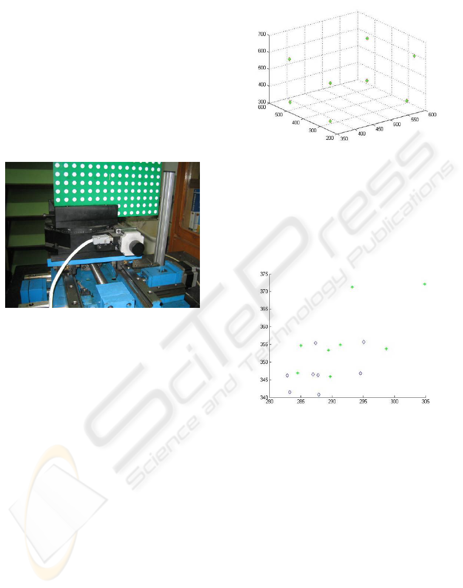
Figure.1 shows its structure.
Figure 1: The experimental system.
The rotating stage is made by Beijing Optical
Instrument Factory, which is mainly used in
reconstructing 3D object for validating the projection
matrix. It can rotate to an arbitrary angle. The
conversion between input pulse and rotating angle is:
X×1.8(electrical pulse angle) = θ×Y×N×Z
where X is the value of input displacement(mm), Y
is pulse equivalent, Z is transmission ratio, N is
subdivision, and θ is the actual rotation
angle(degree).
3.2 Simulation
A simulation is carried out using the MATLAB
toolbox before practical experiments are considered.
The optical axis of camera and the Z-axis of world
coordinate are assumed in the same plane in
emulation. Eight points with known world
coordinates are set in space. It is imaging by two
suppositional cameras. The two cameras have a
rotating movement to the Y-axis of world
coordinate. The following is illustrated in Fig. 2.
Figure 2: The simulation result.
In the figure, the shapes in diamond are the
points we assumed in the space, the shapes in
asterisk are the reconstructed points. The result is
perfectly correct, that is, the reconstructed points are
superposed with the assumed points in the space
each other. Fig.3 shows the points imaged in the two
cameras.
Figure 3: The points imaged on two cameras.
3.3 Practical Implementation
3.3.1 Calibration
In order to improve the precision of 3D
reconstruction, we performed calibration twice from
different angles. At first, we set one of the moving
platform axis vertical with calibration template
through adjusting the fixture device and the rotating
stage. The world coordinate before rotating is
defined as: the X-axis is transverse, Z-axis is
lengthways, Y-axis is vertical, and downward
direction is positive.
The calibration template is fixed on the fixture
device which can ensure the calibration template
parallel with the XOY plane. Therefore it ensures
accurate calculation of the 3D world coordinates.
VISAPP 2007 - International Conference on Computer Vision Theory and Applications
58
With fixing up the camera, we can ensure the
calibration template locating in the visual field of
camera through adjusting the 2D moving platform. A
clear view of the white points in the calibration
template can be obtained by adjusting camera focus.
Then we set the current value of Z-axis as zero and
take the first image, and then move the calibration
template twice forward and backward in Z-direction
by moving platform, 10 millimetres each time. Five
images would be obtained after those operations.
The centre of the circles must be picked for the
following calculation. There are 77 picked points in
every image, and 385 picked points in the space
from five images entirely. After that the projection
matrix will be calculated.
After rotating the rotating stage to an angle, the
same procedure is used to calculate the new
projection matrix. In this case, because the rotating
stage has a relative movement to the moving
platform, so when we confirm the points of world
coordinate, the value of X and the value of Z must be
adjust to fit the geometric relationship changes.
The results are shown as below. The matrix
1
M
is the projection matrix before rotation, the matrix
2
M
is the projection matrix after rotation.
Table 1: Projection matrix
1
M
.
1
M
⎥
⎥
⎥
⎦
⎤
⎢
⎢
⎢
⎣
⎡
+
+
+
−
+
+
−−
+
+−
−
+
+
340.1
550.8
544.4
199.9
282.4
268.5
209.2
351.5
111.2
273.3
146.3
353.5
e
e
e
e
e
e
e
e
e
e
e
e
Table 2: Projection matrix
2
M
.
2
M
⎥
⎥
⎥
⎦
⎤
⎢
⎢
⎢
⎣
⎡
+
+
+
−
+
+
−−
+
+−
−
+
+
333.1
594.7
513.4
190.9
262.4
131.6
201.2
314.5
188.2
135.1
172.8
320.5
e
e
e
e
e
e
e
e
e
e
e
e
In order to check the calibration results, we
reconstruct two points in the space whose world
coordinate is known. Table.3 illustrates the
measurement result.
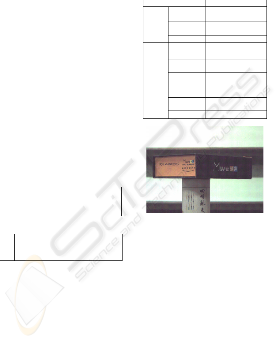
3.3.2 Reconstruction
Afterwards, a book box (Fig. 4) is reconstructed as
an example. Using the calibration, we reconstruct the
box which is normal cuboids. Our primary
assignment is to reconstruct eight corner points on
the cuboids, and review the cuboids through the
eight corner points.
Table 3: The result of reconstructing two points.
name X Y Z
Actual
value(mm)
-53 -44 -63
Reconstructe
d value(mm)
-53.4
0
-44.4
4
-63.6
7
Point1
Error (mm) 0.4 0.44 0.67
Actual
value(mm)
107 -44 -63
Reconstructe
d value(mm)
106.7
-44.7
0
-62.7
7
Point2
Error (mm) 0.3 0.7 0.23
Actual
value(mm)
160
Reconstructe
d value(mm)
160.11
Distanc
e of
P1P2
Error (mm) 0.11
Figure 4: An image of the object to be constructed.
We place the target object on a fixture device by
a holder that in the experiment is a cylinder. When
the rotating stage is rotated each five degrees, we
take an image. In total 72 images were obtained after
360 degree rotation. According to equation (3),
projection matrix after rotating can be obtained.
Choosing two of the images with certain rotation
angle, we can reconstruct some points which both
visible in the two images. From the seventy-two
images, we can reconstruct all the eight points.
Fig.5 shows the reconstructed object. Table.4
shows the world coordinates of the eight points.
Table.5 shows the distance between two points. The
actual values were also compared with reconstructed
values. The maximal error is 2.75 millimetres and
the mean error is 1.34 millimetres. The relative error
is about 1% which is satisfactory for many
applications.
EXPERIMENTAL STUDY FOR 3D RECONSTRUCTION BASED ON ROTATIONAL STEREO
59
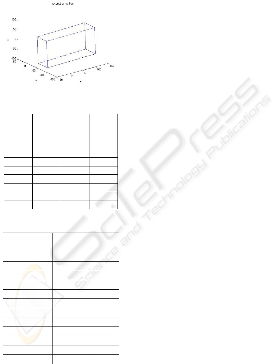
Figure 5: 3D reconstruction result.
Table 4: Eight points reconstructed for the box. Corners.
name
The
value of
X(mm)
The
value of
Y(mm)
The
value of
Z(mm)
Point1 -40.034 -87.892 -83.684
Point2 -39.179 -37.57 -84.615
Point3 -41.726 -85.182 51.852
Point4 -41.215 -36.214 51.56
Point5 149.64 -86.893 -78.562
Point6 149.84 -35.912 -78.383
Point7 145.52 -87.671 56.894
Point8 145.88 -36.512 59.107
Table 5: The lengths of twelve box borders (where DPij is
the distance between Point i and j).
name
Actual
value(mm)
Reconstructed
value(mm)
Relative
error
DP12 50 50.338
0.676%
DP13 138 135.57
1.76%
DP15 190 189.74
0.137%
DP42 138 136.2
1.30%
DP43 50 48.971
2.06%
DP48 190 187.25
1.45%
DP62 190 189.13
0.458%
DP65 50 50.981
1.96%
DP68 138 137.55
0.326%
DP73 190 187.33
1.41%
DP75 138 135.52
1.80%
4 CONCLUSION
In this paper, a 3D reconstruction method based on
rotational stereo is proposed. The object to be
reconstructed is placed on a rotational plate which
can be precisely controlled by a computer. Only one
camera is needed to capture object images and thus it
can reduce the implementation cost and cut down the
times of calibration. Two instances based on the
method are introduced. Eight points are
reconstructed in simulation and a box is
reconstructed in practical experiments for
verification. The results of simulation and practical
experiments are acceptable. The maximal error and
mean error show the method is feasible for many
applications.
The precision of the first case of the method rely
on the precision of fixture device, because the
position of the rotating axis is determined by
geometry of fixture. We used it on the condition that
the position of rotating axis can be ensured
accurately, but it is difficult in reality, or impossible.
The second case of the method does not require that,
but it must ensure the rotating axis is parallel with
V-axis of computer image coordinate. If considering
generally condition, it is complicated to calculate all
parameters and to get projection matrix after rotating
an angle. Our future work will focus on rotational
stereo on a general condition and try to make error
analysis for improving accuracy.
ACKNOWLEDGEMENTS
This work is supported by the National Natural
Science Foundation of China (NSFC No. 60405009,
60605013), ZJNSF [Y104185, Y106065], and
Scientific Research Fund of Zhejiang Provincial
Education Department [20051450]. S.Y. Chen is a
research fellow of the Alexander von Humboldt
Foundation of Germany.
REFERENCES
Consolatina Liguori, Alfredo Paolillo, Antonio Pietrosanto,
2004. An on-line stereo-vision system for dimensional
measurements of rubber extrusions. Measurement 35,
221–231.
Clark F. Olson, Larry H. Matthies, Marcel Schoppers,
Mark W. Maimone, 2003. Rover navigation using
stereo ego-motion. Robotics and Autonomous Systems
43, 215–229.
VISAPP 2007 - International Conference on Computer Vision Theory and Applications
60

J.A. Lines, R.D. Tillett, L.G. Ross, D. Chan ,S. Hockaday,
N.J.B. McFarlane, 2001. An automatic image-based
system for estimating the mass of free-swimming fish.
Computers and Electronics in Agriculture 31,
151–168.
ZHU Hai Jiang, WU Hu Chao, Hu Zhan Yi, 2005.
Camera Calibration Based on Two Paraller Line
Segments. Acta Automatica Sinica Vol.31 No.6
November.
Zhigang Zhu, Deepak R. Karuppiah, Edward M. Riseman,
and Allen R. Hanson, 2004. Dynamic mutual
calibration and view planning for cooperative mobile
robots with panoramic virtual stereo vision. Computer
Vision and Image Understanding 95, 261–286.
J.-S. Liua, J.-H. Chuang, 2002. Self-calibration with
varying focal length from two images obtained by a
stereo head. Pattern Recognition 35, 2937 – 2948.
LiMei Song, DaNv Wang, 2006. A novel grating matching
method for 3D reconstruction. NDT&E International
39, 282–288.
Kyu-Phil Han, Kun-Woen Song, Eui-Yoon Chung,
Seok-Je Cho, Yeong-Ho Ha, 2001. Stereo matching
using genetic algorithm with adaptive chromosomes.
Pattern Recognition 34, 1729-1740.
A. Dipanda, S. Woo, F. Marzani, J.M. Bilbault, 2003.
3-Dshape reconstruction in an active stereo vision
system using genetic algorithms. Pattern Recognition
36, 2143 – 2159.
Gonzalo Pajares, JesuH s Manuel de la Cruz, Jose
Antonio Lopez-Orozco, 2000. Relaxation labeling in
stereo image matching. Pattern Recognition 33, 53-
68.
Jasmine Banks, Mohammed Bennamoun and Peter Corke,
1999. Fast and Robust Stereo Matching Algorithms for
Mining Automation. Digital Signal Processing 9,
137–148.
Ma Song De and Zhang Zheng You, 1998. The computer
vision - calculation theory and algorithm foundation.
Beijing: Science Press.
Marr D. Vision[M] .W. H, 1982. Freeman and Company.
LI Qi, FENG Hua-jun, XU Zhi-hai, HAN Yi-shi, HUANG
Hong-qiang, 1999. Review of computer stereo vision
technique. OPTICAL TECHNIQUE , ISSU 139,
PART 5, pages 71-73.
F. Dornaika and R. Chung, 2000. Cooperative
Stereo–Motion: Matching and Reconstruction.
Computer Vision and Image Understanding 79,
408–427.
M.I.A. Lourakisa, S.T. Halkidisa,S.C. Orphanoudakis,
2000. Matching disparate views of planar surfaces
using projective invariants. Image and Vision
Computing 18, 673–683.
Zhengyou Zhang, 2002. A Flexible New Technique for
Camera Calibration. Technical Report.
MSR-TR-98-71.
EXPERIMENTAL STUDY FOR 3D RECONSTRUCTION BASED ON ROTATIONAL STEREO
61
