
CYLINDRICAL B-SPLINE MODEL FOR REPRESENTATION
AND FITTING OF HEART SURFACES
Ting-ting Jiang, S. Y. Chen, Qiu Guan and Chunyan Yao
College of Information Engineering, ZheJiang University of Technology, HangZhou China
Dept of Informatics, University of Hamburg, Hamburg Germany
Keywords: Model representation, fitting, human heart, cylindrical B-Spline, three-dimensional model.
Abstract: Heart diseases cause high mortality while the therapy of these diseases is still faulty. Consequently recovery
of human’s heart is valuable for clinical diagnosis and treatment. This paper proposes a new approach for
three-dimensional (3-D) representation of external surface of human hearts based on B-Spline model. The
model is represented in both Cartesian and cylindrical coordinates. By comparison, we find that the
cylindrical coordinate is more convenient and much closely fits the structure of human hearts. The fitting is
based on a cloud of points which can be extracted from computed tomography (CT) slices by an edge
detection method. Results show that cylindrical B-Spline with a given number of control points can well fit
the external surface of an artificial heart, which can then be further used for quantitative and functional
analysis of the heart easily and accurately.
1 INTRODUCTION
Research shows heart diseases are the leading cause
of death in west countries and the rate of death are
increasing each year all over the world. If all kind of
those diseases were cured, human life could be much
longer (Frangi, 2001). At present, imaging
techniques, such as magnetic resonance imaging
(MRI), ultrasound, CT, and X-ray, provide
noninvasive methods to study internal organs in vivo.
Visualization of heart has the capability to improve
the diagnostic value of cardiac images. Firstly, many
diseases are strongly correlated to the shape of heart;
Secondly, due to the development of medicinal
imaging techniques, much more useful cardiac
information has been provided while clinical
diagnosis and treatment of cardiac diseases become
more complexity; thirdly, it is the first step to get the
other parameters.
Several techniques have been used to construct
stereo hearts; however, most of the clinical
information for detailed study is still constrained to
two dimensions. In order to solve this problem,
Pentecost et al (1999) use non-uniform rational
B-Spline contours to form embryonic heart surface
model (Fig.1) and the control points of the contours
are identified and outlined manually at each section.
The whole surface is not continuous at all though the
contours are smooth and continuous.
Park et al
(2003) use finite element methods to represent heart
model (Fig.2 right). A static, comprehensive
end-diastolic cardiac surfaces including four cardiac
chambers and connected vasculature are presented as
a triangular mesh (Cristian et al, 2006). Recently,
one of the traditional cardiac models is called VTP
model, heart and left ventricle (LV). Surface can be
viewed in preview by vtp document, but this
software only
connects two adjacent points by lines,
which will lead the surfaces, and it is imprecise to
compute other cardiac parameters. A mass of
attention dedicated to modeling LV model because
many functional parameters are connected with LV.
Though this paper constructs heart surface, we will
describe the methods used to model the LV surface
in the following text. They maybe good ways to
recovery heart surface even the whole heart.
Cardiologists used simplified shapes to approximate
the LV In the early days, for example, Vuille and
Weyman (1994) and Dulce et al (1993)
use simple
ellipsoidal models. However, since it is imprecise
and can offer only few diagnostic parameters.
Recently, three-dimensional surface models and
correlative computer vision or graphics techniques
have been developed to capture the shape and the
other parameters from medical image data (
Park et al,
62
Jiang T., Y. Chen S., Guan Q. and Yao C. (2007).
CYLINDRICAL B-SPLINE MODEL FOR REPRESENTATION AND FITTING OF HEART SURFACES.
In Proceedings of the Second International Conference on Computer Vision Theory and Applications, pages 62-68
DOI: 10.5220/0002064800620068
Copyright
c
SciTePress
1996). These models are finite element model,
physics-based elastic model, bending and stretching
model and B-Spline model etc. Most of those models
are based on simple geometric models. Here gives
the brief introduction of some models. Cauvin et al
(1993) approximate the LV as a truncated bullet,
which is much more close to the real structure of LV
compared to an ellipsoid. Chen et al (1995) apply
superquadrics to model the LV. Staib and Duncan
(1996) use sinusoidal basis functions for shape
recovery.
Haber (2001) gives a 3-D finite element
model, LV was divided into 16 bicubic Hermite
finite elements, although it can provide clinically
important information, it is still coarse. Guo Luo et
al (2004) use b-spline model to construct the LV
(fig.2 left) shape but the LV is considered as a
generalized prolate spheroid.
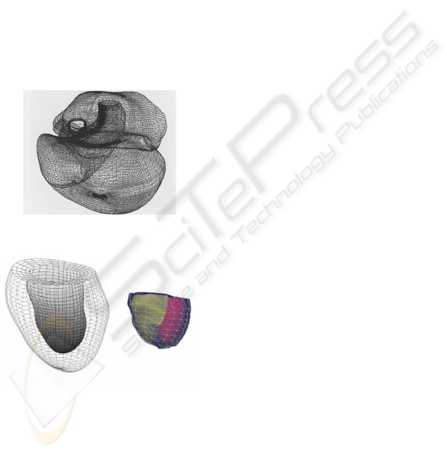
Figure 1: Representation of the embryonic heart
reconstructed by NURBS contours (after Pentecost).
Figure 2: LV model with prolate spheroid fitting by
B-Spline (left). A finite element model uses a generic heart
model to generate a single model (right) (Luo and Park).
Recently, some attention has been given to
surface reconstruction with the introduction of
B-Spline. B-Spline, were introduced by DeBoor
(1978), Ateshian (1993) uses B-spline least-squares
surfaces-fitting method to create geometric models
of diarthrodial joint articular surfaces. The results
prove this method is precise, flexible. Farin (2002),
Farin and Dianne (2000) and Rogers (2001) present
B-Spline surfaces in CAD. B.Zhang (2004)
represents a human head with bi-cubic B-Spline
technique and Klingensmith (2002) uses B-Spline to
model lumen and vessel surfaces. And all the papers
above show that B-Spline surface is a very useful
technique for representing and constructing 3-D
objects.
In this paper, we apply B-Spline to recovery the
shape of a heart. Since B-Spline fitting makes the
surface smooth and continuous. This method doesn’t
make use of geometrical shape of heart, but using an
edge detection method to gain the external surface
points from CT slices of a heart, and we use
B-Spline to fit the heart surface from the achieved
points. This restructured B-Spline surface is much
more smooth and close to the actual data, and is
domain partition. This paper introduces the theory of
B-Spline curves and B-Spline surfaces in Cartesian
and Cylindrical coordinates. Section three shows the
characteristics of B-Spline model and some
parameters which will be analyzed by this B-Spline
model. The performance of the B-Spline method to
recovery of a heart and the results are given in
section four. Section five gives the conclusions and
suggestions for further studies.
2 B-SPLINE
The B-Spline is widely used in 3-D computer
graphics to describe three-dimensional surface,
therefore it is fit for a variety of industrial and
anatomical shapes (Amini et al, 2001), (Nicholas et
al, 2003)
and (Paul et al, 2001). In this section, we
will describe B-Spline model detailedly and a
cylindrical B-Spline model will be proposed to
restructure heart surface.
2.1 B-Spline Curve in Cartesian
Coordinate
A B-Spline curve of order k is expressed as:
)()(
,
0
uNVuP
ki
n
i
i
∑
=
=
G
G
(1)
Where
]...[
,1,0 n
VVVV
K
K
K
G
=
are the sequence of control
points of B-Spline curve, the number of control
points is much fewer than a sampling of the curve
CYLINDRICAL B-SPLINE MODEL FOR REPRESENTATION AND FITTING OF HEART SURFACES
63
)(uP
G
on a pixel grid and
i
V
G
rarely reside on the
actual curve (De Boor, 1978). (n+1) is the number of
control points in the u directions,
)(
,
uN
ki
depending
on the knot vector U=
],...,,[
110 ++kn
uuu
is B-Spline
basis function of degree k, here k<n, because when
k=n B-Spline basis function becomes Bezier basis
function, and when k>n knot vector isn’t existent.
)(
,
uN
ki
is indicated by the following equations:
k=0:
⎩
⎨
⎧
<≤
=
+
otherwise
uuuif
uN
ii
i
0
1
)(
1
0,
k>0:
)()()(
1,1
11
1
1,,
uN
uu
uu
uN
uu
uu
uN
ki
iki
ki
ki
iki
i
ki −+
+++
++
−
+
−
−
+
−
−
=
(2)
According to equation (2) Basis function
)(
,
uN
ki
is
defined by k+2 knots
11
,...,,
+++ kiii
uuu
which are
from U in equation (3).
When k is an even:
N
⎪
⎪
⎭
⎪
⎪
⎬
⎫
+
++
⎪
⎩
⎪
⎨
⎧
=
+
−−
=
−
+
=
+
=
+
+
∑
∑∑
1
12/
1
2/
12/
1
22/
2/
1
12/
1
1,...,1,
2
)(
,...
2
)(
,
2
)(
,0,...,0
k
kn
j
kn
j
k
j
k
j
k
j
k
j
k
L
l
l
L
l
l
L
l
l
U
When k is an odd number:
N
⎪
⎭
⎪
⎬
⎫
⎪
⎩
⎪
⎨
⎧
=
+
−+−
=
++
=
+
=
+
∑∑∑
1
12/)1(
1
12/)1(
1
2/)1(
1
1
1,...,1,
)(
,...,,,0,...,0
k
kn
j
j
k
j
j
k
j
j
k
L
l
L
l
L
l
U
Where
1−
−=
iii
VVl
G
K
,
∑
=
=
n
i
i
lL
1
.
(3)
2.2 B-Spline Surface in Cartesian
Coordinate
A 3D B-Spline surface of degree p in the u direction
and degree q in the v direction is defined as a
piecewise ratio of B-Spline polynomials as given by
the following function:
∑∑
==
=
n
i
m
j
qjpiji
vNuNPvuS
00
,,,
)()(),(
G
G
(4)
where:
S
G
is a point on the surface defined in
Cartesian coordinates (x, y, z), u and v are usually
representing longitude and latitude respectively, n+1
and m+1 are the number of control points in the u
and v directions respectively,
ji
P
,
G
is the
)1()1(
+
×
+
mn
matrix of control points defined in
Cartesian coordinates
),,(
ijijij
zyx
.
)(
,
uN
pi
and
)(
,
vN
qj
are the basic functions in the u and v
direction using degree p and q.
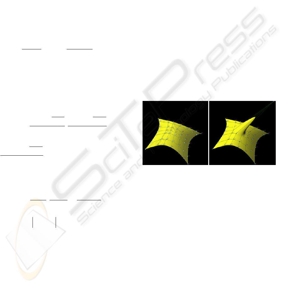
One of important properties of B-Spline is
Local Modification Scheme, for example
)(
,
uN
pi
and
)(
,
vN
qj
is zeros when (u, v) is outside
of the rectangle
),[),[
11 ++++
×
qiipii
vvuu
and is
non-zero on
),[),[
11 ++++
×
qiipii
vvuu
. From this
property, we know that if one control point is moved
to a new location, the following figure show that
only the neighboring area on the surface of the
moved control point changes shape and elsewhere is
unchanged.
Figure 3: Left is the B–Spline surface, and right is the
B-Spline surface that one control point is moved to a new
location.
2.3 B-Spline Surface in Cylindrical
Coordinate
Cylindrical B-Spline model more closely matches
the shape of heart than Cartesian model (Deng et al,
2004) (Fig. 10). Also, it is more convenient for us to
compute volume and analyze other parameters of
human hearts. Consequently, it is necessary to
introduce how to construct such surfaces.
In the similar way to the Cartesian case, a
B-Spline surface can be defined in a system of
cylindrical coordinates
),,( zr
θ
. In order to get the
B-Spline equation in cylindrical coordinates, there
are two steps necessary to do:
Step 1: coordinate transform (Javier, 1995) and (Bae,
2002)
VISAPP 2007 - International Conference on Computer Vision Theory and Applications
64

The given n×m matrix of control points
),,(
ijijij
zyx
in 3D Cartesian coordinates are
transformed into cylindrical coordinate
points
),,(
ijijij
zr
θ
)...1,...1( mjni ==
.
Where
,
22
ijijij
yxr +=
⎪
⎪
⎪
⎩
⎪
⎪
⎪
⎨
⎧
<>+
<+
≥>
<=
>=
=
00)/tan(2
0)/tan(
00)/tan(
002/3
002/
ijijijij
ijijij
ijijijij
ijij
ijij
ij
yandxifxya
xifxya
yandxifxya
yandxif
yandxif
π
π
π
π
θ
ijij
zz =
(5)
Step 2: B-Spline surface formulation
The form of the surface is similar with that have
been given in equation (1), and the surface has the
following system:
∑∑
==
=
n
i
m
j
qjpiij
vNuNrvur
00
,,
)()(),(
∑∑
==
=
n
i
m
j
qjpiij
vNuNvu
00
,,
)()(),(
θθ
∑∑
==
=
n
i
m
j
qjpiij
vNuNzvuz
00
,,
)()(),(
(6)
3 ANALYSIS OF B-SPLINE
MODEL
B-Spline surface model has several characteristics: 1)
the model can be controlled flexibility, that is to say
low degrees surface and several control points can fit
a wished surface, this surface is more realistic than
those based on solid geometry or simple
mathematical relationships. 2) It is a smooth and
continuous model. 3) The model can be modified
locally without changing the shape in a global way.
This trait can be explained by one property of
B-Spline that is local modification scheme which is
introduce in section 2.2, moreover, if fine-tuning
surface shape is required, one can insert more knots
(and therefore more control points) so that the
affected area could be restricted to a very narrow
region. 4) It has a property called affine Invariance,
this property states that when we want to apply a
geometric or even affine transformation to the
B-Spline surface, we can apply the transformation to
control points which is quite easy, and once the
transformed control points are obtained the
transformed B-Spline surface is the one defined by
these new points, we use this characteristic to get the
Cylindrical B-Spline equation.
As the purpose of getting the B-Spline model is
to be further used for functional analysis and
visualization of the heart convenient and exact. The
final cylindrical B-Spline model will be further used
for calculating cardiac functional parameters. In
practice, assessment of cardiac function still relies on
simple global volumetric measures like left
ventricular volume (LVV) and mass (LVM) and
ejection fraction (EF). As many parameters
physician interested rely on LV model which can be
obtained in the same way. In the following
paragraphs, we will introduce some basic parameters
relying on this LV model:
LVV is a basic parameter, which is necessary to
obtain other important parameters, like EF. There are
two general methods have been used to represent the
LVV, one regards the LVV as the volume of a
truncated ellipse. The other uses the sum of multiple
smaller volumes of several slices. But the accuracy
is not enough, especial using the truncated ellipse to
replace the LV. Because of the accuracy of B-Spline
model, LVV would be measured much close to the
actual LVV with the application of B-Spline surface
model, which will improve the future diagnosis. This
is also the goal for further study.
LVM is usually normalized to total body surface
area or weight in order to facilitate interpatient
comparisons. The normal value of LVM normalized
to body weight is 2.4±0.3/kg (Frangi, 2001). LVM
can be calculated by following equation:
)(
endoepi
VVLVM −×=
ρ
(7)
Where
ρ
is the density of the muscle tissue
(1.05 g/cm
3
) (Frangi, 2001), and
epi
V
is the total
volume contained within the epicardial borders of
the ventricle and
endo
V
is the volume of the chamber.
The next parameter is EF which is considered as
one of the most meaningful measures of heart pump
function and can be got by the expression provided
below.
%100×
−
=
EDV
ESVEDV
EF
(8)
Where EDV is the end-diastolic volume and ESV
is the end-systolic volume.
CYLINDRICAL B-SPLINE MODEL FOR REPRESENTATION AND FITTING OF HEART SURFACES
65
4 EXPERIMENTS AND RESULTS
4.1 Data Acquisition
First, with a given number of bitmap images which
correspond to CT slices of an artificial heart, this
paper uses a cardiac model to explain the good effect
of B-Spline fitting which is also fit for reconstructing
LV and other shape. The artificial heart is positioned
on top of a wooden base and is deformable by means
of oil filled syringes which are embedded under the
cardiac surface. CT slices of the heart were acquired
under 3 deformation levels called level_1, level_2
and level_3. The heart was at complete rest while
each one of the 3 CT scans was performed. The
experiment demonstrated in this section is to use
level_1.
Second, extract a cloud of 3D points from the CT
slices. This process can be divided into six parts:
1) Smooth the images by a filter.
2) Stitch the CT slices in the right order into a
single entity according to the provided index files.
3) Define a Region of Interest (ROI) window in
order to maintain the segmentation within a desired
area (Fig. 4). This process bases on simple intensity
threshold, segment the external cardiac surface from
the rest of the heart.
4) Get the grey from the images and calculate
slopes of changes of the grey. Here we define the
point which have maximal slope is the border.
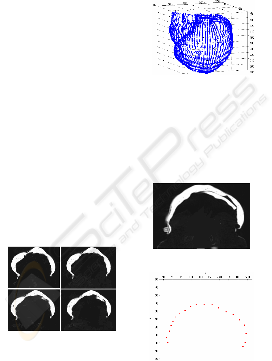
5) Extract a cloud of 3D points.
6) Remove some noises points from the extracted
points manually.
7) View the result (Fig. 6)
Figure 4: Four images which are the ROI areas are
segmented from CT slices.
Figure 5: Discrete cardiac surface.
4.2 2-D B-Spline Curve Fitting
Figure 7 provides 20 points which come from a CT
slice as the control points for B-Spline, compared
this image with figure 6, we can see the outer
contour of the CT slice is expressed by those discrete
points. Figure 9 shows the result of using B-Spline
curve with the degree of 2 to fit the CT slice and the
dots in the picture are the 20 points, according to this
picture we can see that almost all the control points
are near the curve, that is to say the curve is fitted
precisely by B-Spline.
Figure 6: A segmented CT slice which is used to explain
the 2-D B-Spline fitting.
Figure 7: Twenty points from external contour of the slice
given in Figure 6.
VISAPP 2007 - International Conference on Computer Vision Theory and Applications
66
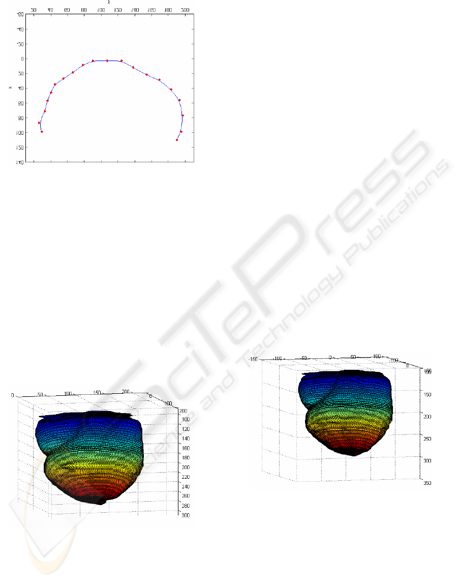
Figure 9: A b-spline curve of the slice.
4.3 3-D B-Spline Surface Fitting
The 3-D surfaces (Fig. 9 and 10) are from 2-D
contours, 2-D curves are blended together to form a
3-D surface, the 2-D points in planes are splined
horizontal curves and this horizontal curves are
splined vertically to create a 3-D surface, this
process is rely to the two basis functions. The
control points extracted from part 4.1 are arrange in
a n×m matrix, each row of the matrix are the points
from a slice, n is the number of points on each slice
and m is the number of slices (here n=25 and m=40).
In the following
parts, we will analyze Cartesian and
Cylindrical model respectively, and finally
compare the two models.
Figure 10: The Cartesian B-Spline surface fitted from the
cloud of points generated in our lab.
1) Cartesian B-Spline surface. Figure 9 displays
the result of using 3-D Cartesian B-Spline of degree
3 in the u direction and degree 3 in the v direction to
represent the surface of the heart from the CT data
set compared to the current B-Spline model based on
prolate spheroid and the FE model. From Figs.1, 2, 5
and 9, it is proved that the B-Spline surface in this
paper is more closely to the real model and it is
continuous and smooth while the prolate
spheroid-based B-Spline given in Fig. 2 left (Guo
Luo et al, 2004) is not precise enough and the FE
model (Park, 2003) is imprecise and not continuous.
As we know, the purpose of modeling, one is for
viewing the shape, and the other is for further
analyzing functional parameters. The B-Spline
model is more likely to compute the parameters
accurately.
2) Cylindrical B-Spline surface. Figure 10 shows
the surface of the heart using 3-D Cylindrical
B-Spline of degree 3 in u and degree 3 in v just the
same degrees as the Cartesian model. The control
points which are the same points given in Cartesian
model are changed into new points with all value of
x subtract 66 and all value of y subtract 124.5. This
change don’t influence the shape of heart but let line
(0, 0, z) be the axis of the heart, and then translating
the new points into Cylindrical coordinate points
(see equation 6).
3) Comparing Fig. 9 with Fig. 10, there is
noobvious difference between the two images,
however cylindrical B-Spline models are more
closely to the original shape at the bottom of the
heart. In conclusion, cylindrical B-Spline model is
more convenient and much closely fits the structure
of human hearts and it is more convenient to get the
clinically important parameters.
Figure 11: The Cylindrical B-Spline surface created from
the same data set.
5 CONCLUSIONS
In this paper, we proposed an efficient method for
representation and visualization of 3D external
surfaces of heart. A heart model was reconstructed
both in Cartesian and Cylindrical coordinates. By
contrast, cylindrical coordinate is more convenient
and much closely fits the structure of human hearts.
CYLINDRICAL B-SPLINE MODEL FOR REPRESENTATION AND FITTING OF HEART SURFACES
67

Further studies show cylindrical B-Spline can also
be used to fit the LV and the RV, even a vivid heart
might be represented by B-Spline model in the future.
It is valuable for the diagnoses of heart diseases, and
series of ongoing studies related on cardiac analysis
are being performed depending on this result, and
thus the cylindrical B-Spline model will be very
useful for us in working out functional parameters of
human hearts.
ACKNOWLEDGEMENTS
The testing image set was provided by Prof. G.
Yang’s research group at the Imperial College
London. This work was supported by the National
Natural Science Foundation of China
[NSFC-60405009, 60605013], [ZJNSF-Y105101,
Y104185], and a grant for Key Research Items from
the Dept of Science and Technology of Zhejiang
Province [2006C21002]. S. Y. Chen is a research
fellow of the Alexander von Humboldt Foundation,
Germany.
REFERENCES
A. F. Frangi, W. J. Niessen, M. A.Viergever, 2001.
Three-Dimensional Modeling for Functional Analysis
of Cardiac Images: A Review. IEEE transactions on
medical imaging, Vol.20.
J. O. Pentecost, J. Icardo, and K. L. Thornburg, 1999. 3D
computer modeling of human cardiogenesis.
Computerized Medical Imaging and Graphics.
K. Park, D. Metaxas, L. Axel, 2003. A Finite Element
Model for Functional Analysis of 4D Cardiac-Tagged
MR Images. Lecture Notes in Computer Science, vol.
p491-498.
Cristian Lorenz, Jens von Berg, 2006. A comprehensive
shape model of the heart, Medical Image Analysis.
C. Vuille and A. E. Weyman, 1994. Left ventricle I:
General considerations, assessment of chamber size
and function. in Principles and Practice of
Echocardiography, 2nd ed.
M. C. Dulce, G. H. Mostbeck, K. K. Friese, G. R. Caputo,
and C. B. Higgings, 1993. Quantification of the left
ventricular volumes and function with cine MR
imaging: Comparison of geometric models with three
dimensional data. Radiology, vol. 188, no. 2, pp.
371–376.
Jinah Park, Dimitri Metaxas, 1996. Deformable Models
with Parameter Functions for Cardiac Motion Analysis
from Tagged MRI Data. IEEE Trans. Medical
Imaging.,15(3): 278~289.
J. C. Cauvin, J. Y. Boire, M. Zanca, J. M. Bonny, J.
Maublant, and A. Veyre, 1993. 3D modeling in
myocardial 201TL SPECT. Computerized Medical
Imaging and Graphics, vol. 17, no. 4–5, pp. 345–350.
C. W. Chen, J. Luo, K. J. Parker, T. S. Huang, 1995. CT
volumetric data-based left ventricle motion estimation:
An integrated approach. Computerized Medical
Imaging and Graphics, vol. 19, no. 1, pp. 85–100.
L. H. Staib, J.S.Duncan, 1996. Model-based deformable
surface finding for medical images. IEEE Trans. Med.
Imag., vol. 15, pp. 720–731.
Idith Haber, Ron Kikinis and Carl-Fredrik Westin, 2001.
Phase-drive finite element model for spatio-temporal
tracking in cardiac tagged MRI. Springer-Verlag
Berlin Heidelberg.
Guo Luo and Pheng Ann Heng, 2004. LV Shape and
Motion: B-Spline Based Deformable Model and
Sequential Motion Decomposition IEEE Trans. Inf
Technol Biomed.
De Boor, 1978. A practical guide to splines. Springer.
Berlin
Farin, G.E., 2002. Curves and Surfaces for CAGD: A
Practical Guide. Kaufmann, San Francisco.
Farin, G.E., Dianne, H., 2000. The Essentials of CAGD.
Peters, Natick, USA.
Rogers, D.F., 2001. An Introduction to NURBS with
Historical. Perspective. Morgan Kaufmann, San
Francisco.
Ateshian, G.A., 1993. A B-Spline least-squares
surface-fitting method for articular surfaces of
diarthrodial joints. J. Biomech. Eng. 115, 366–373.
B.Zhang, J.F.M. Molenbroek, 2004. Representation of
human head with bi-cubic B-Spline technique based
on the laser scanning technique in 3D surface
anthropometry. Applied ergonomics, Elsevier.
Jon D. Klingensmith, D. Geoffrey Vince, 2002. B-Spline
methods for interactive segmentation and modeling of
lumen and vessel intravascular ultrasound.
Computerized Medical Imaging and Graphics.
Pergamon.
Nicholas J. Tustison, Victor G. Dávila-Román, and Amir
A. Amini. 2003. Myocardial Kinematics From Tagged
MRI Based on a 4-D B-Spline Model. IEEE Trans. on
BIOMEDICAL ENGINEERING, Vol. 50.
Amir A. Amini, Yasheng Chen, Mohamed Elayyadi, ,
Petia Radeva, 2001. Tag Surface Reconstruction and
Tracking of Myocardial Beads from SPAMM-MRI
with Parametric B-Spline Surfaces. IEEE Transactions
Medical Imaging.
William Paul Segars 2001. Development and application
of the new dynamic nurbs-based cardiac-torso (NCAT)
phantom. University of North Carolina, MA.
Xiang Deng and Thomas S. Denney, Jr. 2004.
Three-Dimensional Myocardial Strain Reconstruction
From Tagged MRI Using a Cylindrical B-Spline. IEEE
Trans. on MEDICAL IMAGING, Vol. 237.
Javier Sánchez-Reyes, 1995. Quasinonparametric surfaces.
Computer-Aided Design, Vol.27, p263 – 275.
Seok-Hyung Bae, Byoung K. Choi. 2002. NURBS surface
fitting using orthogonal coordinate transform for rapid
product development. Computer-Aided Design. vol. 34,
p683-690.
VISAPP 2007 - International Conference on Computer Vision Theory and Applications
68
