
Uncalibrated Visual Odometry for Ground Plane
Motion Without Auto-calibration
Vincenzo Caglioti
1
and Simone Gasparini
1
Politecnico di Milano - Dipartimento di Elettronica e Informazione
Piazza Leonardo da Vinci, 32 - I-20133 Milano (MI), Italy
Abstract. In this paper we present a technique for visual odometry on the ground
plane, based on a single, uncalibrated fixed camera mounted on a mobile robot.
The odometric estimate is based on the observation of features (e.g.,salient points)
on the floor by means of the camera mounted on the mobile robot.
The presented odometric technique produces an estimate of the transformation
between the ground plane prior to a displacement and the ground plane after
the displacement. In addition, the technique estimates the homographic transfor-
mation between ground plane and image plane: this allows to determine the 2D
structure of the observed features on the ground. A method to estimate both trans-
formations from the extracted points of two images is presented.
Preliminary experimental activities show the effectiveness and the accuracy of the
proposed method which is able to handle both relatively large and small rotational
displacements.
1 Introduction
Robot localization is a fundamental process in mobile robotics application. One way
to determine the displacements and measure the movement of a mobile robot is dead
reckoning systems. However these systems are not reliable since they provide noisy
measurements, due to the slippage of the wheel. Localization methods based only on
dead reckoning have been proved to diverge after few steps [1]. Visual odometry, i.e.
methods based on visual estimation of the motion through images capture by one or
more cameras, is exploited to obtain more reliable estimates. Cameras are mounted on
the robot and the images are processed in order to recover the structure of the sur-
rounding environment and estimate the motion among images captured from different
viewpoints.
Usually, 3D reconstruction from images taken by a moving uncalibrated camera go
through auto-calibration. Autocalibration from planar scenes requires either nonplanar
motion [2], or several planar motions with different attitudes of the camera wrt the
ground plane [3].
In a mobile robotics framework, however, changing camera attitude requires addi-
tional devices as, e.g., pan-tilt heads, not directly connected to the robot functionality.
In particular, mounting a fixed monocular camera on a mobile robot does not allow to
change the camera attitude wrt to the ground plane, making auto-calibration impossible
Caglioti V. and Gasparini S. (2007).
Uncalibrated Visual Odometry for Ground Plane Motion Without Auto-calibration.
In Robot Vision, pages 107-116
DOI: 10.5220/0002067301070116
Copyright
c
SciTePress

without additional information. A similar scenario is that of a fixed camera mounted on
a moving vehicle (such as, e.g., a road car).
However, in this paper we will present a technique for visual odometry on the
ground plane, based on a single, uncalibrated fixed camera mounted on a mobile robot.
The mobile robot is supposed to move on a planar floor, called ground plane. No map of
the environment is needed. The odometric estimate is based on the observation of fea-
tures (e.g., salient points) on the floor by means of the camera mounted on the mobile
robot.
The presented odometric technique produces an estimate of the transformation be-
tween the ground plane prior to a displacement and the ground plane after the displace-
ment. In addition, the technique estimates the homographic transformation between
ground plane and image plane: this allows to determine the 2D structure of the observed
features on the ground, as a side effect. The presented technique does not determine the
camera calibration parameters.
However, it is argued that any further step towards auto-calibration is not needed in
the context of mobile robot odometry. In fact, auto-calibration would only allow to de-
termine the spatial transformation between ground plane and camera: auto-calibration
alone does not allow to determine the robot-to-camera transformation. Therefore, de-
termining the transformation between the robot and the ground plane should require
further extrinsic calibration steps: these steps could consist in e.g., acquiring visual data
while the robot is executing self-referred displacements (such as, a self-rotation and a
forward translation).
On the other hand, the presented technique for visual odometry estimates the trans-
formation between ground prior to a displacement and ground after the displacement.
If needed, the robot-to-ground calibration can be accomplished by the same additional
step, namely visual observation of self-referred robot displacements, required when
starting with auto-calibration.
The technique works for generic planar displacements, but it does not work for
translational displacements. However, once the homography between ground plane and
image plane has been determined as a side effect, further displacements, including pure
translations, can be analyzed directly by using the (inverse) homography.
1.1 Related Works
In the last years methods to estimate the robot motion (ego-motion) based on visual
information provided by cameras have gained attention and some approaches have been
presented. Early methods were based on estimation of the optical flow from image
sequence in order to retrieve ego-motion. McCarthy and Barnes [4] presented a review
and a comparison between the most promising methods.
Other approaches exploited stereo vision. Nister et al. [5] proposed a method based
on triangulation between stereo pairs and feature tracking in time-sequence of stereo
pairs, without any prior knowledge or assumption about the motion and the environ-
ment. Takaoka et al. [6] developed a visual odometry system for a humanoid robot
based on feature tracking and depth estimate using stereo pairs. Agrawal and Konolige
[7] proposed an integrated, real-time system involving both stereo estimate in the dis-
parity space and a GPS sensor in a Kalman filter framework. GPS-based systems can be
108

sufficiently accurate for large areas but it can be not used in indoor environments and
require a support framework, which prevent their use, e.g., for planetary exploration.
For such application, Mars Exploration Rover [8] employed a features detection in a
stereo image pair that are tracked from one frame to the next; using maximum like-
lihood estimation the change in position and attitude for two or more pairs of stereo
images is determined.
Davison [9] proposed a real-time framework for ego-motion estimation for a single
camera moving through general unknown environments. The method was based on a
Bayesian framework that detect and track a set of features (usually corner, points or
lines). Assuming the rigidity in the scene, the feature image motion allows to estimate
the motion of the camera; therefore the complete camera trajectory and a 3D map of all
the observed features can be recovered.
Visual odometry system based on catadioptric cameras have been proposed. Bun-
schoten and Krose [10] used a central catadioptric camera to estimated the relative pose
relationship from corresponding points in two panoramic images via the epipolar geom-
etry; the scale of the movement is subsequently estimated via the homography relating
planar perspective images of the ground plane. Corke et al. [11] developed a visual
odometry system for planetary rover based on a catadioptric camera; they proposed a
method based on robust optical flow estimate from salient visual features tracked be-
tween pairs of images, by which they retrieve the displacements of the robot.
Our approach is similar in spirit to the work of Wang et al. [12] who measured
translation and rotation by detecting and tracking features in image sequences; assum-
ing that the robot is moving on a plane, they computed the homography between the
image sequences by which the computed the motion. Similarly, Benhimane and Malis
[13] developed a visual servoing framework based on the estimation of the homogra-
phy between image sequences to retrieve robot motion and close the control loop. Both
methods require camera calibration. Our work differ from these approaches in that we
do not assume camera calibration.
The paper is structured as it follows. Section 2 introduces and describes the ad-
dressed problem. Section 3 shows how the robot displacement can be retrieved by fit-
ting the homography between two images of the ground plane. Section 4 illustrates the
method to estimate the transformation between the ground plane and the image plane.
Section 5 reports and discussed some preliminary experimental activities performed
with a rotating camera. Section 6 concludes the paper.
2 Problem Formulation
A mobile robot moves on the floor. A fixed, uncalibrated camera is mounted on the
mobile robot: this camera is supposed to be a perspective camera (i.e., distortion is
neglected). The pose of the camera relative to the robot is unknown. The environment
map is unknown, as well as the structure of the observable features (associated to floor
texture) on the ground. This allows extremely easy set-up: it is sufficient to mount a
perspective camera on the mobile robot in a fixed but unknown position.
For the rigid body consisting of the robot plus the camera, a “ground” reference
frame is defined as follows: the backprojection O of a certain image pixel (say, the pixel
109

O
′
with cartesian coordinates (0, 0)) on the ground plane is taken as the origin of the
projected reference frame, while vector connecting the origin to the backprojection A
of a second image pixel (say, the pixel A
′
with cartesian coordinates (100, 0)) on the
ground is taken as the unit vector along the x-axis.
As usual within the Robotics and Vision communities, homogeneous coordinates
are used. Let T be the unknown 3× 3 matrix representing the projective transformation,
also called “homography”, between the ground plane and the image plane, as realized
by the uncalibrated camera. The coordinates on the ground plane are referred to the
above defined ground reference frame of the robot+camera system. Therefore, the un-
known homography T does not change with robot motion.
As the robot moves on the ground plane, the robot+camera undergoes a planar mo-
tion consisting of a rotation of an unknown angle θ about an unknown vertical axis. Let
C be the point where this vertical axis crosses the horizontal ground plane. Let R be the
rotation matrix describing the planar displacement. The matrix R is a 3× 3 2D rotation
matrix in homogeneous coordinates, whose third column collects the homogeneous co-
ordinates of the center of rotation C relative to the robot+camera ground reference and
whose upper-left 2× 2 sub-matrix is orthogonal.
Two images are taken: the first one is taken before the displacement, while the sec-
ond one is taken after the displacement. The addressed problem is the following: first,
given the transformation between the first and the second image, determine the center
of rotation, and the rotation angle of the observed displacement; second, determine the
transformation T between the ground plane and the image plane, and use the inverse
transformation T
−1
to measure further displacements. The inverse transformation T
−1
can also be used to determine the shape (i.e., the 2D structure) of the set of the observed
features on the ground.
An interesting problem, which is not addressed in this paper, is that of finding a
transformation between the ground robot+camera reference frame and a second refer-
ence frame, more significant to the robot kinematics. This transformation can be esti-
mated by applying the presented odometric technique to self-referred robot displace-
ment, as e.g., a “self”-rotation and a “forward” translation.
3 Estimation of Robot Displacement
The transformation relating the two images of the ground plane is still a homography,
and it is represented by the matrix H = TRT
−1
, where T is the unknown homography
between ground plane and image plane. (In principle, camera distortion can be compen-
sated by imposing that the transformation between the two images is a homography.)
The homography H between the two images (before and after the displacement) can
be computed from a sufficient number of pairs of corresponding features between the
two images [14].
The eigenvectors of the homography matrix H are given by C
′
= TC, I
′
= TI and
J
′
= TJ, where the rotation center C, and the circular points I and J are the invariants
under rotation R on the ground plane. In addition, the eigenvalues of H coincide with
the eigenvalues of R (modulo a scale factor).
110

The eigenvectorC
′
is associated to the real eigenvalue of H, while I
′
and J
′
are asso-
ciated to the complex eigenvalues of H. By the eigendecomposition of the homography
matrix H, the parameters of the planar displacement are determined.
In particular, the imageC
′
of the center of rotationC is determined as the eigenvector
correspondingto the real eigenvalue of H. The rotation angle θ is determined as the ratio
between imaginary part and real part of the complex eigenvalue, in fact the eigenvalue
corresponding to I
′
= TI is given by µe
±iθ
, where µ is a real scale factor.
If the displacement is a pure translation, then the images of all the points at the
infinity are eigenvectorsof H. Therefore the translation direction can not be determined.
Therefore, displacements with small rotation angles may generate solutions, that are
numerically unstable.
4 Estimation of the Transformation Between the Ground Plane
and the Image Plane
The shape of the observed features is determined by estimating the transformation
matrix T. This matrix can be estimated by four pairs of corresponding points: these
can be, e.g., the two circular points I = [1, i, 0]
T
, J = [1, −i, 0]
T
with their image
projections I
′
, J
′
, plus the two points defining the robot+camera ground reference,
namely O = [0, 0, 1]
T
and A = [1, 0, 1]
T
, with their image projections O
′
= [0, 0, 1]
T
and A
′
= [100, 0, 1]
T
.
The homogeneous (world) coordinates of O within the ground reference are [0, 0, 1]
while the homogeneous coordinates of A within the ground plane are [1, 0, 1]. With
these choices, the transformation matrix T between ground plane and image plane is
fully constrained, and it can be determined, imposing that
I
′
= TI
J
′
= TJ
O
′
= TO
A
′
= TA
Once the transformationmatrix T has been estimated, the shape of any configuration
of observed features can be determined by their images (P
′
i
, i = 1..n) by P
i
= T
−1
P
′
i
. The
knowledge of T allows to determine the coordinates of the rotation center C = T
−1
C
′
relative to the (back-projected) robot reference. The estimated motion parameters con-
stitute an odometric estimate of the robot displacement.
Notice that the shape determination requires that the displacement is not purely
translational. However, once the transformation T has been determined by analyzing
a rotational displacement, it can be used also to measure purely translational displace-
ments.
5 Preliminary Experimental Results
In order to validate the proposed method we performed some experimental activities.
111
500 600 700 800 900 1000 1100
0
0.5
1
1.5
2
2.5
3
3.5
4
4.5
5
(a)
400 500 600 700 800 900 1000 1100 1200
0
1
2
3
4
5
6
7
(b)
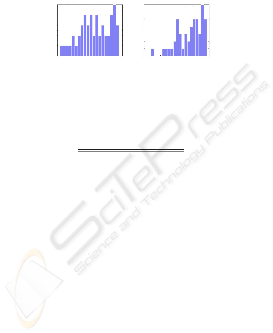
Fig.1. The distribution of the matching score of the features used to estimate θ
5,6
(a) and θ
6,7
(b).
Table 1. The first sequence of 7 images taken with relatively large rotational displacements. The
table reports the ground truth references (θ
ref
, in degrees) read on the turntable, the rotational
displacements between two consecutive images (θ
i,i+1
), the estimated rotational angles (
ˆ
θ
i,i+1
)
and the relevant error (e
ˆ
θ
i,i+1
). The value of θ
6,7
was obtained with a lower number of features
(N = 10) since many outliers were found.
Step θ
ref
θ
i,i+1
ˆ
θ
i,i+1
e
ˆ
θ
i,i+1
1 107 9 9.37 -0.37
2 116 8.5 8.09 0.41
3 124.5 10.5 10.35 0.15
4 135 8 7.91 0.09
5 143 11 10.97 0.03
6 154 10.5 9.70 0.8
In our experimentations we use a standard perspective camera provided with a very
low distortion optics. The camera was placed on a turntable by which we manually
measured the ground truth rotation with an accuracy of about 0.5
◦
. The camera view-
point was placed in a generic position relative to the rotation axis: therefore the camera
underwent a general planar motion. The camera was pointed towards the ground floor,
such that the extraction of salient points exploits the floor texture. Then we took some
images with different rotational displacement and applied the proposed method in order
to estimate the rotation angle between two images.
We tested the method on two sequences of images. The first sequence was obtained
considering larger rotational displacements, with a mean angle of about 10
◦
. The second
sequence is characterized by relatively small rotational displacements between images.
The mean rotational displacement of this set is about 5
◦
. As discussed in Section 3,
small rotation angles may lead to numerical instability. On the other hand if the robot
rotates slowly,images with small rotational displacementshave to be taken into account.
Table 1 collects the ground truth values, the estimated values and the relevant errors
for the first sequence. For this sequence we employed the following estimation proce-
dure. Given two consecutive images, say I
i
and I
i+1
, we extracted a number of salient
112

Table 2. The second sequence of 25 images taken with relatively small rotational displacements.
For each step, the table reports the ground truth references (θ
ref
, in degrees) read on the turntable,
the relative rotational displacements among the three consecutive images (θ
i,i+1
and θ
i,i+2
), the
estimated rotational angles (
ˆ
θ
i,i+1
) and the relevant error (e
ˆ
θ
i,i+1
).
Step θ
ref
θ
i,i+2
θ
i,i+1
θ
i+1,i+2
ˆ
θ
i,i+2
e
ˆ
θ
i,i+2
1 321 12 7 5 11.83 0.17
2 314 12 5 7 12.16 -0.16
3 309 8.5 7 1.5 7.83 0.67
4 302 10 1.5 8.5 10.81 -0.81
5 300.5 14 8.5 5.5 7.97 6.03
6 292 10 5.5 4.5 9.25 0.75
7 286.5 7.5 4.5 3 7.03 0.47
8 282 10 3 7 9.36 0.64
9 279 12 7 5 11.58 0.42
10 272 10.5 5 5.5 9.93 0.57
11 267 9.5 5.5 4 8.70 0.80
12 261.5 10.5 4 6.5 9.96 0.54
13 257.5 10.5 6.5 4 10.02 0.48
14 251 9 4 5 8.71 0.29
15 247 7 5 2 7.50 -0.50
16 242 8 2 6 7.01 0.99
17 240 10 6 4 9.03 0.97
18 234 10.5 4 6.5 10.78 -0.28
19 230 10 6.5 3.5 9.52 0.48
20 223.5 10 3.5 6.5 10.91 -0.91
21 220 10 6.5 3.5 10.72 -0.72
22 213.5 7.5 3.5 4 7.21 0.29
23 210 8.5 4 4.5 8.96 -0.46
points from each image using the Harris features extractor [15]. Then we found the
correspondences among these points using the normalized cross correlation and we se-
lected a set of points (usually, N = 20) having the best matching score [16]. We used
this set of points to fit the homography H
i,i+1
using the RANSAC technique [17] pro-
vided by [18]. Once H
i,i+1
was computed, we estimated the rotation angles from the
complex eigenvalues of H
i,i+1
, as explained in Section 3.
As Table 1 shows, the estimates are very accurate and the errors are less than 1
◦
. The
value of θ
6,7
was obtained considering a lower number of salient point, N = 10. Because
of the large rotational displacement (about 10.5
◦
) the matching among features was in
most cases incorrect and the resulting matching score was (on the average) higher with
respect to the other images of the sequence. Figure 1 compares the distributions of the
matching score values of the first 50 best matches for image pairs used to compute c
and θ
6,7
respectively: the estimation process of θ
5,6
can rely on many reliable match-
ing features (e.g. at least 20 matches have a matching score less than 800) while for the
estimation process of θ
6,7
there are only few matches under the same threshold. This in-
troduced many outliers that affected the estimate. Decreasing the number of considered
points allowed to discard many outliers, thus obtaining a more reliable estimate.
Table 2 collects the ground truth values, the estimated values and the relevant errors
for the second sequence. In order to overcome possible numerical instability issues we
used three images to robustly estimate the angle. We employed the following estimation
procedure. Given three consecutive images, say I
i
, I
i+1
and I
i+2
, we extracted a number
of salient points from each image, say c
i
, c
i+1
and c
i+2
respectively. We found the
113
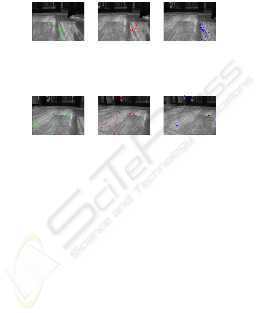
(a) Image 1 (b) Image 2 (c) Image 3
Fig.2. An example of tracked features between three images. The first two images (a,b) are
compared in order to find the best matches (depicted in green and red, respectively). The best
features of (b) are matched with (c) in order to find the best matches (depicted in blue in (c)).
Hence the chain of matches between the images are used to computed the homography H
i,i+2
.
(a) Image 5 (b) Image 6 (c) Image 7
Fig.3. The images (from 5 to 7) of the second sequence for which the estimated rotation angle
was incorrect. The found corresponding features among images are depicted: most of the matches
are false matches, which led to an incorrect estimation of the homography H
5,7
.
correspondences among the features c
i
and c
i+1
, selecting only those matches having
the best matching score, say c
′
i
and c
′
i+1
. Then we tracked these matches in I
i+2
by
matching c
′
i+1
with the features c
i+2
, selecting the best matches and obtaining c
′′
i+1
and
c
′′
i+2
(where c
′′
i+1
⊆ c
′
i+1
).
Exploiting c
′′
i+1
, we also obtained c
′′
i
, which are features of I
i
that have a matching
feature both in I
i+1
and I
i+2
. By fitting a homography with c
′′
i
and c
′′
i+2
, we computed
the 3x3 matrix H
i,i+2
with the RANSAC technique, obtaining the relevant rotation angle
θ
i,i+2
. Figure 2 shows an example of the tracked features among the three images.
The reported results proved the effectiveness and the accuracy of the proposed
method. The estimation errors are less than 1
◦
, except for images 5, 6 and 7. In this
case the errors is greater since the method was not able to find a correct rotational
angle. This is due to the large displacements among images: the overall displacement
between image 5 and 7 is about 14
◦
, with partial displacements of 8.5
◦
and 5.5
◦
respec-
tively. Figure 3 shows the matching feature that are used to determine the rotational
displacements: there are many false matching that affected the estimate of θ
5,7
.
Large displacements may cause such errors since we used the normalized cross cor-
relation to find the correspondences. Normalized cross correlation is not rotationally
invariant, hence large rotation can corrupt the matching process. Moreover, large rota-
114

tion angles between images reduce the overlapping region of the images, thus reducing
the number of corresponding features. In order to overcome these issues, rotationally
invariant matching function can be employed such as, e.g., SIFT features extractor [19].
On the other hand, in a real application a proper visual sampling rate during robot move-
ment would avoid large displacements between two poses.
6 Conclusions and Ongoing Activity
In this paper we presented a novel method to estimate the odometry of a mobile robot
through a single uncalibrated fixed camera. Assuming that the robot is moving on a
planar floor, images of the floor texture is taken. Salient points are extracted from the
image and are used to estimate the transformation between the ground plane before
a displacement and the ground plane after the displacement. The proposed technique
also estimate the homography between the ground plane and the image plane, which
allows to determine the 2D structure of the observed features. An estimation method
of both transformations was described. Preliminary experimental activities that vali-
date the method for small and large rotational displacements are also presented and
discussed.
Ongoing works are aimed at improving the estimate method in order to provide
reliable estimate in presence of large rotational displacements. Other experimental ac-
tivities will be conducted in order to better stress the method in different situations. We
are also planning to implement a real time version of the proposed method on a real ap-
plication in order to use the odometric estimate for localization tasks in a mobile robots.
Other possible future research direction are the employment of catadioptric cameras in
order to exploit their large field; however, using catadioptric cameras the transforma-
tions are not homography, unless central catadioptric cameras are used, which are, on
the other hand, difficult to set up.
References
1. Borenstein, J., Feng, L.: Measurement and correction of systematic odometry errors in mo-
bile robots. IEEE Transaction on Robotics and Automation 12 (1996) 869–880
2. Triggs, B.: Autocalibration from planar scenes. In: Proceedings of the European Conference
on Computer Vision (ECCV ’98), London, UK, Springer-Verlag (1998) 89–105
3. Knight, J., Zisserman, A., Reid, I.: Linear auto-calibration for ground plane motion. In: Pro-
ceedings of the IEEE International Conference on Computer Vision and Pattern Recognition
(CVPR ’03). Volume 1., Los Alamitos, CA, USA, IEEE Computer Society (2003) 503–510
4. McCarthy, C., Barnes, N.: Performance of optical flow techniques for indoor navigation
with a mobile robot. In: Proceedings of the IEEE International Conference on Robotics and
Automation. Volume 5., Los Alamitos, CA, USA, IEEE Computer Society (2004) 5093–
5098
5. Nister, D., Naroditsky, O., Bergen, J.: Visual odometry. In: Proceedings of the IEEE Inter-
national Conference on Computer Vision and Pattern Recognition (CVPR ’04). Volume 1.,
Los Alamitos, CA, USA, IEEE Computer Society (2004) 652–659
6. Takaoka, Y., Kida, Y., Kagami, S., Mizoguchi, H., Kanade, T.: 3d map building for a hu-
manoid robot by using visual odometry. In: Proceedings IEEE International Conference
115

on Systems, Man, and Cybernetics. Volume 5., Los Alamitos, CA, USA, IEEE Computer
Society (2004) 4444–4449
7. Agrawal, M., Konolige, K.: Real-time localization in outdoor environments using stereo vi-
sion and inexpensive gps. In: Proceedings of the International Conference on Pattern Recog-
nition (ICPR ’06). Volume 3., Los Alamitos, CA, USA, IEEE Computer Society (2006)
1063–1068
8. Cheng, Y., Maimone, M., Matthies, L.: Visual odometry on the mars exploration rovers
- a tool to ensure accurate driving and science imaging. IEEE Robotics and Automation
Magazine 13 (2006) 54–62
9. Davison, A.: Real-time simultaneous localization and mapping with a single camera. In:
Proceedings of the IEEE International Conference on Computer Vision (ICCV ’03), Los
Alamitos, CA, USA, IEEE Computer Society (2003) 1403–1410
10. Bunschoten, R., Krose, B.: Visual odometry from an omnidirectional vision system. In:
Proceedings of the IEEE International Conference on Robotics and Automation. Volume 1.,
Los Alamitos, CA, USA, IEEE Computer Society (2003) 577–583
11. Corke, P., Strelow, D., Singh, S.: Omnidirectional visual odometry for a planetary rover. In:
Proceedings of the IEEE/RSJ International Conference on Intelligent Robots and Systems.
Volume 4., Los Alamitos, CA, USA, IEEE Computer Society (2004) 4007–4012
12. Wang, H., Yuan, K., Zou, W., Zhou, Q.: Visual odometry based on locally planar ground as-
sumption. In: Proceedings of the IEEE International Conference on Information Acquisition.
(2005) 6pp.
13. Benhimane, S., Malis, E.: Homography-based 2d visual servoing. In: Proceedings of the
IEEE International Conference on Robotics and Automation, Los Alamitos, CA, USA, IEEE
Computer Society (2006) 2397–2402
14. Hartley, R.I., Zisserman, A.: Multiple View Geometry in Computer Vision. Second edn.
Cambridge University Press (2004)
15. Harris, C., Stephens, M.: A combined corner and edge detector. In: Proceedings of the
Fourth Alvey Vision Conference. (1988) 147–152
16. Torr, P.H.S., Murray, D.W.: Outlier detection and motion segmentation. In Schenker, P.S.,
ed.: Sensor Fusion VI, SPIE volume 2059 (1993) 432–443 Boston.
17. Fischler, M.A., Bolles, R.C.: Random sample consensus: a paradigm for model fitting with
applications to image analysis and automated cartography. Communication of ACM 24
(1981) 381–395
18. Kovesi, P.D.: MATLAB and Octave functions for computer vision and image processing.
School of Computer Science & Software Engineering, The University of Western Australia
(2004) Available from:
http://www.csse.uwa.edu.au/
˜
pk/research/matlabfns/
.
19. Lowe, D.G.: Distinctive image features from scale-invariant keypoints. International Journal
of Computer Vision 60 (2004) 91–110
116
