
HIERARCHICAL BRAIN MODEL FOR COREGISTRATION
A Physical Model for Analysis of Brain MRI Data
Terrence R. Oakes
Waisman Center Brain Imaging Lab, University of Wisconsin-Madison
1500 Highland Ave., Madison, Wisconsin, USA
Keywords: Physical Model, MRI.
Abstract: A ubiquitous problem in coregistration of brain images is that individual sulci and gyri vary considerably
between individuals, both with respect to location and shape as well as for simple existence of particular
sulci. The underlying assumption of most coregistration processes is that one structure can be smoothly
morphed to exactly resemble another structure if enough parameters are used. Although in a strict sense this
may be true for intersubject brain registration, due to differing structures the result may not be as
meaningful as desired. The proposed approach offers a groundbreaking alternative to the standard approach
of continuously deformable coregistration algorithms, introducing instead a hierarchical structure of related
nodes (a "nodetree") to model the brain structure using grey-matter and white-matter masks. Additionally, a
proposal is made for using the nodetree structure for coregistration, employing a novel locally discontinuous
but focused registration to more accurately align and compare corresponding features. This approach can
provide a framework for identifying structural differences, with a goal of relating them to functional
differences. Although this method uses the brain as an example, it is quite general and not limited to the
brain, or even to medical images.
1 INTRODUCTION
Current mainstream coregistration packages for
medical images use variations of one of two basic
approaches: a) whole-brain voxelwise or volumetric
registration which minimizes a cost function
summarizing the average difference between two 3D
volumes (Woods et al, 1998), or b) registration of
discrete points or features, with the transforms for
nearby unmarked voxels determined by interpolation
(Pelizzari et al., 1989). A feature common to both of
these approaches is to treat the structure as a
continuous 3-dimensional object, so that although
voxels may get stretched or distorted, neighboring
voxels remain neighbors. One result of this
assumption is that missing or extra structures in
either the target or object volume determines the
ultimate accuracy of the procedure. To date,
increases in accuracy have been achieved by using a
larger number of parameters to improve local fits,
but the fundamental assumption is that one structure
can be smoothly morphed to become identical to
another. In brain imaging, frequently there is not a 1-
to-1 intersubject correspondence of structures, so
even if an algorithm is able to smoothly morph one
object to achieve a good pixel-intensity match with
another, the result is not always desirable (Fig. 1).
Current approaches to brain coregistration are
limited to a large extent by the underlying similarity
of the structures to be registered, in that there is no
acknowledgment or allowance for missing or extra
structures. For example, a common but difficult
problem is to accurately register a brain containing a
tumor to a standard brain template. A more subtle
but also more ubiquitous problem is the fact that
individual gyri and sulci vary considerably between
individuals, both with respect to location and shape
as well as for simple existence of particular gyri.
Current coregistration approaches can reshape a
gyrus with some success, but do not address the fact
that a gyrus present in one individual may be
missing in another. The sensitivity of a multi-subject
functional activation study [e.g. functional Magnetic
Resonance Imaging (fMRI) or Positron Emission
Tomography (PET)] is directly related to the
accuracy of combining and examining the same
functional signal from a group of subjects, and
anatomical variation is emerging as one of the
103
R. Oakes T. (2007).
HIERARCHICAL BRAIN MODEL FOR COREGISTRATION - A Physical Model for Analysis of Brain MRI Data.
In Proceedings of the Second International Conference on Computer Graphics Theory and Applications - GM/R, pages 103-108
DOI: 10.5220/0002073201030108
Copyright
c
SciTePress

Figure 1: Cartoon showing two different cortical-like structures (1a, 1b) that cannot be meaningfully morphed to achieve a
similar shape. Cartoons 1c, 1d demonstrate typical results expected from a continuously deformable coregistration model.
1c: a fit using fewer parameters might result in a single gyrus from the object image (blue) spanning two gyri in the target
image (orange). 1d: a fit using a large number of parameters could deform the single gyrus to achieve an accurate pixel
intensity match, but there may not be a physiological justification for splitting a single gyrus into two. 1e: an example of a
more physiologically plausible scenario, where two gyri should match but there is an “extra” or unassigned gyrus. This
result is quite difficult to obtain for current smoothly morphing algorithms.
limiting factors in functional comparisons (Juch et
al., 2005). This paper seeks to establish a framework
for applying established skeleton-based, hierarchical
registration techniques to anatomical medical
images, and subsequently to related functional data.
The nodetree method is based on a variant of the
Medial Axis Transform (MAT), which seeks to
define a skeleton representative of the major features
of an image. The medial axis (MA) (Blum 1967) is
described as the locus of the centers of all bi-tangent
circles contained within a shape. Here, the term
"MA" is used as shorthand for the MAT skeleton. A
useful feature of the MA is that the skeletal pixels
are connected, so shape features such as length are
easily computed. Pixels in a MA skeleton can be
ranked post-hoc according to how many branches
radiate from them, so that node points can be easily
identified. However, one of the lingering problems
with the MA and related approaches is a lack of
robustness (see e.g. Parker 1997). Small changes in
the overall structure can lead to large changes in the
final MA structure, which makes it difficult to apply
this approach to a variety of situations. A number of
variants have been proposed to address this
shortcoming, such as a recent method using a
Bayesian probabalistic approach to estimate a
skeleton shape (Feldman & Singh, 2006), and which
seems to be more robust to noise and minor
perturbations. However, this and similar approaches
have not yet been widely tested on medical images.
A major advance in the MA with respect to
medical imaging was a generalization to 3
dimensions (Sherbrooke et al. 1996). Further
refinements were added by Amenta and Kolluri
(2001) to develop a 3D medial axis from a union of
overlapping balls. In this case, the medial axis is not
a series of lines, as in the 2D case, but rather a group
of vertices that define a closed surface in space.
Ranjan and Fournier (1996) proposed using a union
of balls to describe a volume, and furthermore they
developed a method to coregister two similar
structures by finding the closest spatial match
between corresponding pairs of balls.
One of the major benefits of a hierarchical
skeletal model is that the various branches may be
moved independently of one another. This concept
underlies much of the computer animation field,
where a skeletal model is wrapped with an outer
surface so changes in the orientation and shape of
the skeleton can be propagated to the surface
structures (see e.g. Gagvani et al. 1998). This
process has an innate hierarchy, since movements to
one element of the skeleton (e.g. the forearm) lead to
predictable changes in subservient elements (e.g. the
hand).
The nodetree approach combines many of these
aspects, including ideas from the MA, the union-of-
balls, and the hierarchical skeleton. Unlike a MA,
the nodetree does not need to include all pixels
connecting the nodes. The goal is to produce a
hierarchical skeleton to which volumetric data can
be associated in a robust and logical manner. The
nodetree is a collection of nodes with essential
properties of location, spatial domain, and lineage.
All other properties can be derived from these,
including internode distance, object distance, and
included pixels.
The novelty of the nodetree is in the integration
of the MA and union-of-balls ideas to create a
skeleton. The particularly innovative aspect is the
subsequent coregistration approach it will enable
which is not spatially continuous, but rather which
recognizes that different structures (e.g. brains) may
have different spatial structures performing the same
function. Current alternatives which attempt to
GRAPP 2007 - International Conference on Computer Graphics Theory and Applications
104
match such disparate structures using a continuous
model reduce the achievable accuracy of
coregistrations and also reduce the sensitivity of
related functional activation analysis. This paper
seeks to develop a framework for addressing and
facilitating the comparison of objects with
topologies and/or morphologies which are not
mutually deformable.
2 METHODS
2.1 Nodetree Properties
Construction of a nodetree for the brain starts with a
binary image of the White Matter (WM) tissue,
which can be readily obtained using standard
neuroimaging software , e.g. BET (Smith 2002). The
nodetree attempts to model the WM projections
(gyri) to the cortical Gray Matter (GM) surface. To
be useful as a medium for identifying specific
cortical structures and for intersubject registration,
there are several fundamental properties that each
nodetree should have:
1) Each gyrus should be principally
represented by one major node at the distal
end (apex);
2) There should be a node at every gyral
opening and branch point;
3) Lines connecting nodes must stay within
the tissue type;
4) The size of each node should be relative to
the volume of surrounding WM;
5) Node importance is directly related to node
size;
6) Each node must have only one parent.
This semantic description will be used as the
guiding principal behind the nodetree algorithms.
Current standard skeletal approaches were unable to
yield the desired characteristics, leading to the
development of the current nodetree approach.
2.2 Nodetree Algorithm
A prototype software program has been developed to
create and prune a 2D nodetree. Ultimately, a fully
3D implementation is desired, but the software and
examples presented in this paper are for the 2D case,
in order to simplify initial algorithm development
and display of results.
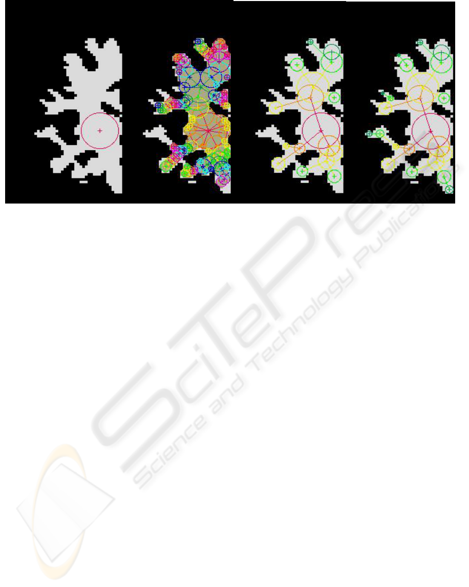
The algorithm starts with a seed-point that all
subjects can be expected to have, such as the center
of the largest WM region. The largest possible circle
is drawn within this region (Fig. 2a) and assigned a
rank of 1. This circle defines a "node" whose
properties include the location, radius, rank, and a
unique identification number. In the second step, the
edge pixels of this circle are used as seed-points for
Figure 2: Creation of a nodetree in the left hemisphere of a coronal section. (2a): The initial node is created by filling the
region near a seed point with the largest possible circle. (2b): Children nodes are added to each node until the structure is
filled. The brown color shows pixels that are included inside a node. The color of each node indicates its rank or generation
number, repeating in order over red, orange, yellow, light green, green, light blue, blue, purple, and magenta. (2c): The
nodetree is pruned to remove small and/or redundant nodes, leaving behind only nodes needed to define the WM structure.
(2d): Six additional nodes (green and dark green) have been added manually using a semiautomated GUI in order to define
the structure more accurately.
HIERARCHICAL BRAIN MODEL FOR COREGISTRATION - A Physical Model for Analysis of Brain MRI Data
105

a new set of circles or "child nodes". For each node,
the goal is to create a family of children nodes
centered on the parent’s edge pixels, and to retain
only children nodes which are large and do not
overlap other sibling nodes. Proceeding from the
largest child to the smallest, siblings within each
child node are eliminated, leaving a few larger
children surrounding the parent. The children nodes
are assigned a parent node as an additional innate
property, and several convenience properties, such
as an "arm length" or distance to the parent node.
This process proceeds iteratively until the entire
object is filled with nodes (Fig. 2b). The full node-
set can be saved for later use.
An important property of nodetree growth is that
at each iteration, growth only occurs for nodes
created in the previous iteration, and this growth is
limited to previously unclaimed regions. We
hypothesize that this will produce a natural growth
pattern that is reproducible across similar branching
structures. This property also helps to ensure that the
initial full nodetree has a closed surface.
2.3 Nodetree Pruning
To emphasize its basic shape, the nodetree must be
pruned so that only the important nodes remain. In
principle, it is desirable for the nodetree algorithm to
yield a description of the object which needs little
post-processing; however in practice, some level of
post-processing (pruning) is required to better
emphasize the overall WM structure. Pruning is not
a single step, but rather is a series of algorithms
which can be varied ad infinitum to emphasize
various characteristics of the underlying structure.
In the current MRI example, the goal is to
represent the overall shape of the WM structures
with the fewest number of nodes. It is not necessary
(and unlikely) that all WM pixels be contained
within a node after this step. An "important" node
meets one of the following criteria: it is a) large and
in the center of a WM space; b) at the end of a WM
gyri; c) at a fulcrum (bend) in a gyral projection or
d) at the mouth (opening) of the gyrus into a larger
WM region. Specific parameters for each of these
criteria can be varied for different effects; for
instance, decreasing the minimal acceptable size for
a terminal node [criteria b) above] can more
accurately model the full extent of a WM gyrus, but
perhaps at the expense of indicating the importance
of the node terminus based on its size.
A series of automated pruning algorithms were
developed to remove small nodes, similar
neighboring nodes, and redundant nodes along a
straight path (Fig. 2c). Some pruning steps may
result in a node changing position and/or radius.
Although the goal is for full automation, the
nodetree can be adjusted manually to make sure that
all arms are filled in and that the nodes are located
properly (Fig. 2d). Either manual or automated
adjustment of individual nodes is simple, due to the
hierarchical compostion of the nodetree. After
pruning, the arm-lengths are recalculated and ranks
are re-assigned to minimize the number of ranks. A
variety of algorithms were developed for the pruning
stages, including functions such as: remove dead-
end nodes; remove nodes below a specified size;
consolidate long runs of nodes by removing nodes
that have only a single child; consolidate ranks to
remove gaps; remove nodes that are too close to
their parents.
3 RESULTS
A nodetree was created for each of 7 normal subjects
using a coronal slice of the left hemisphere from the
same location after the image data were coregistered
to the MNI T1 template (Evans et al., 1993) using
registration software from SPM2
(http://www.fil.ion.ucl.ac.uk/spm/) and skull-
stripped with BET (Smith 2002). Tissue segment
maps were produced using FAST (Zhang et al.,
2001). An 8th nodetree was created using the sum-
image of the segment maps. Similarity of the
nodetrees in Fig. 3 indicates the robustness of this
technique across individuals. The differences help to
highlight the variation in anatomic structure between
individuals.
While there is clearly room for improvement, all
of the nodetrees show similarities, and all are able to
define the overall shape of the WM, including most
of the larger arms.
The nodetree represents a significant data
reduction technique. Figure 2a shows a typical 2D
image of WM with 1018 WM pixels. The full
nodetree (Fig. 2b) contains ~92% of the WM pixels
yet is represented by only 126 nodes. The final
pruned nodetree (Fig. 2d) contains only 21 nodes,
but still captures the shape of the WM structure.
This savings is expected to be proportionally even
greater for 3D data using a nodetree comprised of
spheres. Furthermore, since the pruned structure is
represented by so few points, it is very efficient to
manipulate the structure.
GRAPP 2007 - International Conference on Computer Graphics Theory and Applications
106
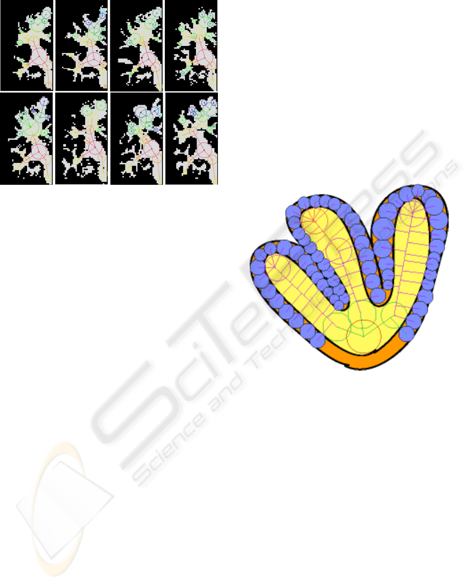
Figure 4: Cartoon showing a 2D scheme for arranging
Gray Matter (GM) nodes within cortical GM and for
associating them to the White Matter (WM) nodetree. The
color of the line connecting each GM node indicates the
line segment of the WM it belongs to. The GM nodes have
a radius designed to span the cortex at each node's
location. Although the GM nodes are depicted as disks in
this cartoon, they could be irregularly shaped in order to
cover all of the GM yet prevent overlap of node interiors.
Figure 3: Comparison of nodetrees from 7 different
subjects. The nodetree at the upper left was derived from
the thresholded WM segment from a sum-image of the
individual segment maps, and can be considered as a basis
for comparison.
Although a nodetree can model a fairly complete
representation of an object, it should be emphasized
that the nodetree is not required to exist in isolation.
For detailed analysis of a shape, the original object
and its underlying data values may be interrogated
as long as nodetree-related spatial transforms are
recorded.
Figs. 2b-d illustrate a potential problem for the
nodetree: one of the terminal gyri remains unfilled
Fig. 2b-c) and has been manually filled in (Fig. 2d).
This is a result of the minimal acceptable node size,
which in this example is a 5-pixel cross-shape.
Using a smaller node (single pixel) or permitting the
search to proceed via diagonal pixels (i.e. pixels
touching at only a corner) solves this problem, but
must be balanced against the increased complexity
of the nodetree shape. The non-minimal node size is
used in Fig. 2 to highlight this tradeoff, in which a
more complex initial nodetree would require
additional pruning. In the current implementation,
the pruning is insufficiently developed to yield
robust results for a very complex nodetree.
Initial attempts to characterize the robustness of
the nodetree indicate that it can be quite sensitive to
noise in the binary WM representation. For example,
a single non-WM pixel in the center of a large WM
space will yield a number of small nodes
surrounding the non-WM island, rather than the
expected single large node. This is really more of a
problem related to creation of the initial binary
image, and isolated non-WM pixels can easily be
removed by standard filtering techniques.
An additional observation is that, while the
nodetree is not overly sensitive to minor changes in
the edge of a structure, the position of nodes at the
end of a gyrus can be sensitive to the width of the
gyrus in relation to the minimal acceptable node
size. Currently, a dedicated pruning step is needed to
minimize this, but further investigation of the
growth pattern with respect to this bias is needed.
In order to be useful for anatomical coregistration, a
systematic identification of important nodes is
required. For example, a template based on a large
number of individuals could label those nodes which
occur most frequently. Once a WM nodetree has
been created, the gray matter cortex could be
modeled as an additional layer, as represented in
Fig.4.
4 CONCLUSION
The nodetree algorithm can yield a reasonably
similar model of the brain white matter structure
across individuals. Further advances, particularly
with respect to pruning, are expected to yield
improved similarity. The hierarchical structure is
well suited as a framework for investigating non-
continuous spatial registration approaches.
HIERARCHICAL BRAIN MODEL FOR COREGISTRATION - A Physical Model for Analysis of Brain MRI Data
107

REFERENCES
Amenta N and Kolluri RK, 2001. The medial axis of a
union of balls, Computational Geometry (20):25-37.
Blum H, 1967. A Transformation for Extracting New
Descriptors of Shape, Symposium Models for Speech
and Visual Form, Weiant Whaten-Dunn (Ed).
Cambridge, MA: MIT Press.
Evans AC, Collins DL, Mills SR, Brown ED, Kelly RL,
Peters TM, 1993. 3-D statistical neuroanatomical
models from 305 MRI volumes, Proc IEEE Nucl Sci
Symp Med Imaging, 95:1813-1817.
Feldman J and Singh M, 2006. Bayesian estimation of the
shape skeleton, PNAS, 103(47):18014-18019.
Gagvani N, Kenchammana-Hosekote D, Silver D, 1998.
Volume Animation Using the Skeleton Tree, Proc.
IEEE Symposium on Volume Visualization.
Juch H, Zimine I, Seghier ML, Lazeyras F, Fasel JHD,
2005. Anatomical variability of the lateral frontal lobe
surface: implication for intersubject variability in
language neuroimaging, NeuroImage, 24:504-514.
Parker JR, 1997. Algorithms for Image Processing and
Computer Vision, John Wiley & Sons.
Pelizzari CA, Chen GTY, Spelbring DR, Weichselbaum
RR, Chen CT, 1989. Accurate three-dimensional
registration of CT, PET, and/or MR images of the
brain, J. Comput. Assist. Tomogr., 13(1):20-26.
Ranjan V and Fournier A, 1996. Matching and
Interpolation of Shapes using Unions of Circles,
Computer Graphics Forum, 15(3):129-142.
Sherbrooke EC, Patrikalakis NM, Brisson E, March 1996.
An Algorithm for the Medial Axis Transform of 3D
Polyhedral Solids, IEEE Trans. on Visualization and
Computer Graphics, v.2 n.1, p.44-61.
Smith SM, 2002. Fast robust automated brain extraction.
Human Brain Mapping, 17(3):143-155.
Woods RP, Grafton ST, Watson JDG, Sicotte NL,
Mazziotta JC, 1998. Automated image registration I:
Intersubject validation of linear and nonlinear models,
J. Comput. Assist. Tomogr., 22(1):153-165.
Zhang Y, Brady M, Smith S, 2001. Segmentation of brain
MR images through a hidden Markov random field
model and the expectation maximization algorithm,
IEEE Trans. on Medical Imaging, 20(1):45-57.
GRAPP 2007 - International Conference on Computer Graphics Theory and Applications
108
