
MECHANICAL PERFORMANCE OF A MANIPULATOR IN
VIRTUAL REALITY SYSTEMS
Jose San Martin
Department of Computers Architecture, Universidad Rey Juan Carlos, Madrid, Spain
Gracian Trivino
Department of Photonic Technology, Universidad Politecnica, Madrid, Spain
Keywords: Virtual reality, Haptic interface, Manipulability, Mechanical Performance.
Abstract: Frequently, the human interface of a virtual reality system includes a 3D manipulator. In order to optimize
the use of this device, the designer must take into account its mechanical characteristics. An obvious design
criterion consists of maximizing the coincidence between the application 3D space and the physical volume
where the manipulator provides its maximum performance. This paper explains in detail the analysis of
manipulability for the PHANToM OMNi haptic device including the study of the manipulability
distribution into its real workspace boundaries. As result of this study we will define a measure of the
quality of the device placement inside the virtual reality system platform. We apply this measure for
designing the mechanical configuration of a simulator for Minimally Invasive Arthroscopic Surgery.
1 INTRODUCTION
1.1 Object of Study
At the moment of evaluating the performance of a
mechanical manipulator, one of the elements to
consider is its capability for reaching and moving
around the different points belonging to the
workspace. Depending on the application
requirements and on the device features it will allow
the transmission of movement and force with major
or minor difficulty up to the end of the kinematics
chain. These characteristics are associated with the
concept of manipulability that this work describes
thoroughly in section 4.
We use the PHANToM OMNi of SensAble
Technologies, that is a well known haptic device
(SensAble Technologies, 2004), to describe and
demonstrate the contributions of this work.
1.2 Defining Workspaces
We introduce three definitions relative to the device
working area:
(a) Nominal Workspace (NW). This is the
volume in which the manufacturer guarantees the
specified force feedback and precision. For the
OMNi device it is a rectangular prism of dimensions
160 W x 120 H x 70 D mm.
(b) Real Workspace (RW). This is the volume
that we can reach with the End Effector. Note that
RW includes a marginal zone where performance of
the device can be unacceptable for some
applications.
(c) Effective Workspace (EW). It is the volume
of the application, so it is different in each system.
For instance it is the working space used by a
surgeon inside of a knee in a simulation of
Minimally Invasive Surgery. In this paper we will
show the relevancy of the shape and size of the EW
for the aim of obtaining a good device performance.
1.3 PHANTOM OMNi Device
Figure 1 identifies the main mechanical components
of the OMNi device: Element A (Head) turns around
Y axis (yaw), defining angle θ
1
. Element B (Crank)
turns around X axis (pitch), defining angle θ
2
.
Element C (Connecting Rod) turns around X’
relative axis (pitch), defining angle θ
3
. Elements D
235
San Martin J. and Trivino G. (2007).
MECHANICAL PERFORMANCE OF A MANIPULATOR IN VIRTUAL REALITY SYSTEMS.
In Proceedings of the Second International Conference on Computer Graphics Theory and Applications - AS/IE, pages 235-240
DOI: 10.5220/0002073302350240
Copyright
c
SciTePress
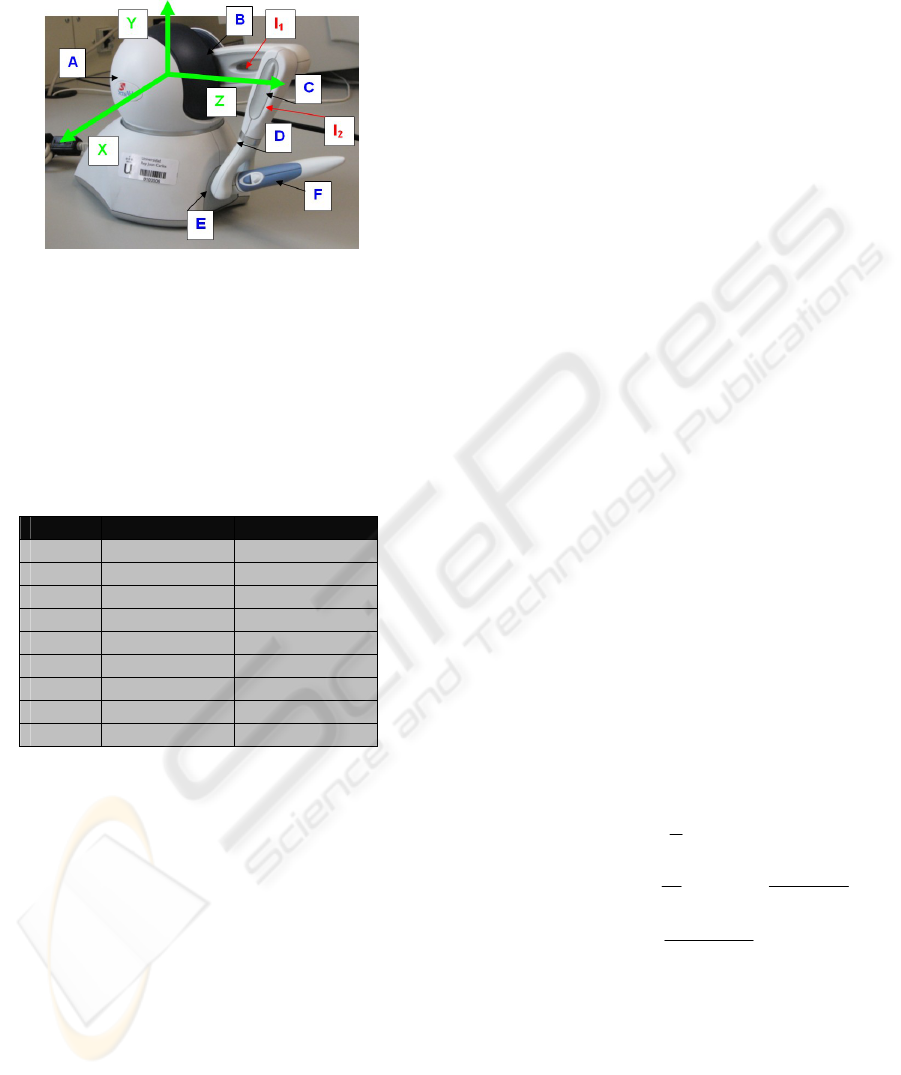
(Wrist), E (Fork) and F (Stylus) turn around
orthogonal axes located at the End Effector and are
the Gimbal angles.
Figure 1: Different Components of the OMNi device.
Coordinate System (CS) XYZ in the origin. Arms
l
1
=129mm and l
2
=133 mm.
As far as we are interested in study the
movement of the point where force feedback is
applied, we will not consider the three gimbal
elements (D, E and F).
Table 1: Relative values of θ
3
depending on θ
2
(value of
the angles in degrees).
θ
2
θ
3 minimum
θ
3 maximum
0 -20 65
15 -15 90
30 -9 105
40 0 110
50 10 112
60 20 113
80 40 114
90 50 114
105 60 110
For this device, values of θ
1
range from -50º to
55º and values of θ
2
range from 0º to 105º. Note that
there is kinematics cylindrical symmetry for θ
1
values. Due to the Omni mechanical design, range of
θ
3
is not constant and depends on the value of θ
2
and
on the angle inter-arms (l
1
-l
2
). Table 1 shows the
correspondence between these angles.
2 KINEMATICS
References (Cavusoglu, Feygin and Tendick, 2002)
and (Rodriguez and Basañez, 2005) describe a
similar kinematics analysis of a former PHANToM
haptic device version.
In this study the Coordinate System Origin
(CSO) is the center of the element A.
2.1 Forward Kinematics
It is the expression of the End Effector position in
Cartesian coordinates in function of the angles of the
joints θ
i
:
()
321
,,),,(
θ
θ
θ
Fzyx
=
From the geometrical relations between the
elements in figure 2, adding sequentially the
transformations T01, T02 and T03, we obtain the
transformation matrix T04 from CSO to the End
Effector position:
⎟
⎟
⎟
⎟
⎟
⎠
⎞
⎜
⎜
⎜
⎜
⎜
⎝
⎛
+−−
+−
+−
1000
)sin()cos()cos()cos()cos()cos()sin()cos()sin(
)sin()cos()sin()cos(0
)sin()sin()sin()cos()sin()cos()sin()sin()cos(
31221131311
213233
31212113311
θθθθθθθθθ
θθθθ
θθθθθθθθθ
ll
ll
ll
Where the sub-matrix R04, is the system rotation
matrix:
⎟
⎟
⎟
⎟
⎠
⎞
⎜
⎜
⎜
⎜
⎝
⎛
−−
−
=
)
3
cos()
1
cos()
3
sin()
1
cos()
1
sin(
)
3
sin()
3
cos(0
)
1
sin()
3
cos()
3
sin()
1
sin()
1
cos(
04
θθθθθ
θθ
θθθθθ
R
And the coordinates of the End Effector referred
to CSO are the last column of T04.
x=
13221
sin)sincos(
θθθ
ll +
y=
3221
cossin
θ
θ
ll
−
z=
13221
cos)sincos(
θ
θ
θ
ll
+
2.2 Inverse Kinematics
It consists of the expression for the angles θ
i
of each
joint in function of the End Effector position
Cartesian coordinates:
()
zyxI ,,),,(
321
=
θ
θ
θ
Almost directly and using the cosine theorem we
obtain:
θ
1
=
)arctan(
z
x
−
;
θ
2
=
)arctan(
H
y
+ )
2
arccos(
1
2
2
2
1
2
Ll
llL −+
θ
3
= )
sin
cos
arctan(
21
21
yl
lH
−
−
θ
θ
3 JACOBIAN CALCULATION
Given a function F: R
n
→ R
m
with m components y
1
to y
m
each of them with n independent variables x
1
to x
n
, the Jacobian consists of the matrix of partial
derivatives of y
i
respect of each one of the x
i
.
GRAPP 2007 - International Conference on Computer Graphics Theory and Applications
236
⎟
⎟
⎟
⎟
⎟
⎟
⎟
⎠
⎞
⎜
⎜
⎜
⎜
⎜
⎜
⎜
⎝
⎛
∂
∂
∂
∂
∂
∂
∂
∂
=
n
x
m
y
x
m
y
n
x
y
x
y
J
...
1
.....
1
...
1
1
The upper half of the Jacobian represents the
relation that exists between the linear velocities of
the End Effector with the angular velocity of the
joints:
V=Ju · dθ/dt
The lower half represents the relation between
the angular velocity of the End Effector with the
angular velocity of the joints:
ω = J
l
· dθ/dt
In the case of the OMNi, upper half of the J has
the dimensions (3xn) where n is the number of
degrees of freedom. For this device the Jacobian is:
⎟
⎟
⎟
⎟
⎟
⎟
⎟
⎟
⎠
⎞
⎜
⎜
⎜
⎜
⎜
⎜
⎜
⎜
⎝
⎛
−
−−
−
+
=
00)sin(
00)cos(
100
)sin(0
0)cos(0
00)sin()cos(
3
3
2321
321
3221
θ
θ
θθ
θθ
θθ
ll
l
ll
J
4 MANIPULABILITY
Manipulability is the skill in transmitting movement
and applying forces in arbitrary directions (Park and
Kim, 1998). We can also say that the manipulability
of a device indicates its ability to move freely in all
the directions in the workspace (Murray, Li and
Sastry, 1994). Another definition is that
manipulability is the efficiency with which a
manipulator transmits force and velocity to its End
Effector (Staffetti, Bruyninckx and De Schutter,
2002).
4.1 Calculation of Manipulability Map
The manipulability of a device was conceptually
defined by (Salisbury and Craig, 1982) and the first
formulation that allowed a mathematical simple
quantification was brought up by (Yoshikawa,
1985).
A widely used algebraic definition of
manipulability is the one by (Yoshikawa, 1990).
,)Ju'*(Judet =
μ
Where Ju is the upper part of the Jacobian and
Ju’ is its transposed one. Others authors propose
different formulations for the Manipulability. For
example (Cavusoglu, Feygin and Tendick, 2002)
(Tavakoli, Patel and Moallem, 2004) make use of:
μ = σ
min
(J
u
)/σ
max
(J
u
) (1)
Where σ
min
and σ
max
are the minimum and the
maximum of the singular values of J
u
.
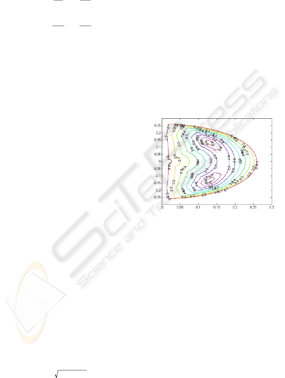
4.2 Map of Manipulability
Figure 2 shows the map of curves of iso-
manipulability in the plane X=0 (θ
1=
0) calculated by
(1). Because the Jacobian does not depend on θ
1
, the
manipulability is equal for any plane defined by a
value of θ
1
.
Figure 2: Iso-manipulability curves map for plane X=0.
Axis values in meters. Curves contain values of µ.
4.3 Real Workspace
According to the θ
1
, θ
2
and
θ
3
ranges in table 1 we
can describe the maximum area that End Effector
can reach in the plane YZ. The real workspace-RW
is defined by this curve. This evolving curve is
projected on the map of manipulability and so we
can extract the portion of the map that the End
Effector can really reach (fig. 3).
MECHANICAL PERFORMANCE OF A MANIPULATOR IN VIRTUAL REALITY SYSTEMS
237
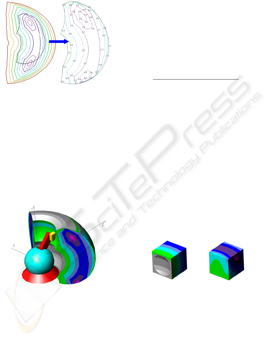
Figure 3: Projection of the real workspace on the
manipulability map and Subspace of manipulability
defined for the real workspace.
Note that, in the Omni device, the best values of
manipulability are included in the real working area.
5 3D MAP OF MANIPULABILITY
Integrating the 2D surfaces of iso-manipulability we
can generate volumes containing points with equal
value of µ. Figure 4 shows the 3D Map of
Manipulability associated to the PHANToM OMNi
device. It will be useful to the designer of a new
virtual reality system to consider this volume as a
virtual part of the OMNi.
Figure 4: Scheme of the 3D Map of Manipulability for the
OMNi.
6 VOLUMETRIC AVERAGE
MANIPULABILITY
This section concerns with the study of how to
situate the OMNi in the system mechanical platform
to obtain its maximum performance.
The EW is a 3D volume that must be situated
inside the 3D map of Manipulability. The
intersection from both solids determines different
values of µ in EW indicated by different sub
volumes vi (different colors in figure 4). The total
volume V
T
is:
n
n
i
iT
vvvvV +++==
∑
...
21
We define Volumetric Average Manipulability
as:
V
) v·µ v·µ v·µ v· (µ
µ
T
nn332211
v
………+++
=
(2)
Where µ
i
is the Manipulability in each v
i
.
This measure is useful to do a quantitative
comparison between different possible mechanical
configurations of a system using manipulators.
7 THEORETICAL EXAMPLES
We have designed four tests, each one with two
options for placing the Effective Workspace, in
order to verify the usability of the Volumetric
Average Manipulability µ
v
.
Test A. EW is a cube of L=100mm:
Case A1. We place the center of gravity (CG) at
150 mm from the origin along the axis Z. After
calculation, formula (2) produces: µ
v
=0.5411.
Case A2. We place it in the neighborhood of the
optimal manipulability values zone, CG at position
XYZ (-10, 94, 151) mm. After calculation it
produces: µ
v
= 0.7103 sensitively higher.
Figure 5 shows the intersections of the EW with
the solid of manipulability. Cases A1 and A2.
Figure 5: Intersection of the workspaces with the solid of
manipulability.Test A.
Test B. EW is a rectangular squared-base prism
of side L=100mm and height H=200mm:
Case B1. CG of the prism at (-10, 14, 151). The
Manipulability obtained is µ
v
=0.6422 (fig. 6).
Case B2. We situate it, lying down on a plane
parallel to the XZ, fitting in the ideal zone of
manipulability. First we translate GC of the prism at
(5, 92, 161) and a turning of 45 º with regard to an
axis parallel to the Z axis that crosses the CG. The
GRAPP 2007 - International Conference on Computer Graphics Theory and Applications
238
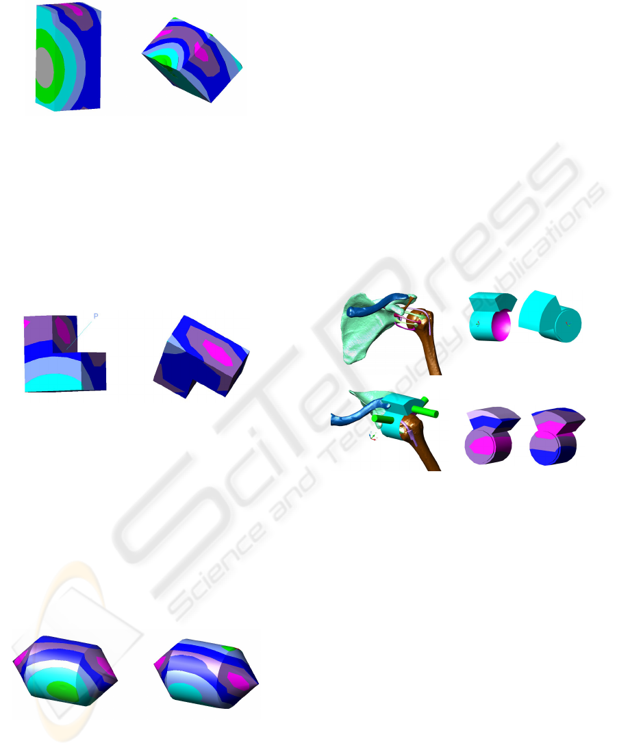
value obtained is µ
v
=0.7353 (fig. 6). Note that this
high value has been obtained by inclining the OMNi.
Figure 6: Intersection of the EW with the solid of
manipulability. Test B.
Test C. EW is an L-shaped solid of side
L=50mm + rectangular prism of square base of side
L=50mm and height H=100mm:
Here, not only it is need to align the EW with the
optimal zone of the manipulability map, but also to
modify the orientation. For the case C1 it has been
obtained a value of µ
v
=0.7730 (fig. 7). In the second
case C2 by means of two turning, we get a value of
µ
v
=0.8336 (fig. 11).
Figure 7: Intersection of the EW with the solid of
manipulability. Test C.
Test D. EW is a solid of revolution axis Y (D:
100 mm): cylinder (H: 90 mm) with a cone (H:
50mm) in each of the bases and a hollow in its
interior.
Case D1. Turn of -90º around axis Z. We move
the CG from CSO at position XYZ (21, 107, 148).
After calculation it produces: µ
v
=0.7618 (fig. 8).
Case D2. Turn of -90º around axis Z. We move
the CG from CSO at position XYZ (-14, 114, 163)
avoiding the hollow of the solid. After calculation it
produces: µ
v
=0.7829 (fig. 8).
Figure 8: Intersection of the EW with the solid of
manipulability. Test D.
This Test D simulates a more complex and not
homogeneous EW, similar to a cavity in a virtual
surgical simulation, being the hollow an unreachable
space, for example a bone, where we are not
interested in optimizing µ.
8 DESIGN OF AN APPLICATION
This section describes a real application of the ideas
developed above. It consists of the positioning of the
OMNi device when used as a component of a
simulator for training in Minimally Invasive
Arthroscopic Surgery (Bayona, Garcia, Mendoza
and Fernandez, 2006), (GMV, 2006). This study is
centered in a virtual model of the human left
shoulder.
Figure 9-1 shows an anatomical model of this
joint where the subacromial capsule has been
suppressed. In this case the EW has two spaces quite
differenced that we name EW-glenohumeral and
EW-subacromial.
1. Anatomical model
2. Two views of EW
3. Shoulder view plus
EW. Portals in green.
4. Results of study of µ
v
cases 1 and 2.
Figure 9: Study of µ
v
in a real implementation.
EW-glenohumeral is the domain of surgeries
such as acromioplasty and it has been modeled using
two cylinders and a spherical hollow. EW-
subacromial is the domain of surgeries such as
arthroscopic labrum fixation and it has been
modeled using a pipe sector. Nevertheless there are
operations, as the diagnostic arthroscopy, which
cover both spaces (Giacomo and Constantini, 2004).
Figure 9-2 shows two views of the whole EW.
Figure 9-3 shows this EW in its placement into
the anatomical model. Note that portals for surgical
instrumentation access (green colored in the figure)
are not included in the µ
v
study because that space
has not meaningful value. Also here, two cases have
been considered (fig. 9-4):
Case 1. EW situated matching the CG of EW-
glenohumeral with the maximum manipulability
zone; position XYZ (85, 118, 148). The aim of this
MECHANICAL PERFORMANCE OF A MANIPULATOR IN VIRTUAL REALITY SYSTEMS
239

approach is obtaining optimal manipulability values
in EW-glenohumeral. After calculation it produces:
µ
v
=0.8073 in the whole of EW. Analyzing them
separately, we obtain µ
v
=0.8873 for EW-
glenohumeral and µ
v
=0.7194 for EW-subacromial.
Case 2. CG of EW situated at maximum
manipulability zone, position XYZ (85, 118, 148).
The criterion is to obtain maximum average
manipulability values for all the EW. After
calculation it produces: µ
v
=0.8506 in the whole of
EW. Analyzing them separately, we obtain
µ
v
=0.8291 for EW-glenohumeral and µ
v
=0.8749 for
EW-subacromial.
9 CONCLUSIONS
A complete study about different workspaces to
distinguish in the environment of a haptic device has
been analyzed.
The need of establishing a criteria for helping the
mechanical design of a simulator of Minimally
Invasive Arthroscopic Surgery has lead us to
contribute in this field by creating a measure that we
have called Volumetric Average Manipulability (µ
v
).
A set of different configurations can be valued in
order to choose the best option. This new concept
will be able to help in the optimal design of a system
involving some haptic device.
The use of this measure has been demonstrated
in several cases of theoretical Effective Workspaces.
A study on the real case of a virtual human shoulder
joint involving the PHANToM OMNI haptic device
has been presented.
ACKNOWLEDGEMENTS
The authors are grateful to the Modeling and Virtual
Reality Group (GMRV) of the Rey Juan Carlos
University.
This work has been partially funded by the
Spanish Ministry of Education and Science (grant
TIC2003-08933-C02-01), Government of the
Community of Madrid (grant GR/SAL/0940/2004
and grant S-0505/DPI/0235).
REFERENCES
Bayona S., Garcia M., Mendoza C., Fernandez, J.M.,
Shoulder Arthroscopy Training System with Force
Feedback, pp. 71-76, International Conference on
Medical Information Visualisation-BioMedical
Visualisation (MedVis'06), 2006.
Cavusoglu, M. C., & Feygin, D. and Tendick F. A Critical
Study of the Mechanical and Electrical Properties of
the PHANToM Haptic Interface and Improvements for
High Performance Control. Teleoperators and Virtual
Environments, 11(6):555--568, 2002.
Di Giacomo, G. Costantini, A. Arthroscopic shoulder
surgery anatomy: Basic to advanced portal placement.
Operative Techniques in Sports Medicine, Volume
12, Issue 2, Pages 64-74 G, 2004.
GMV, Universidad Rey Juan Carlos, Universidad
Politecnica de Madrid, Hospital Severo Ochoa de
Leganes, Virtual Reality Arthroscopy Trainer.
Technological Innovation for improving minimally
invasive surgery skills, 2006.
http://www.insightmist.com/index_en.htm
Murray, R. M., Li, Z., & Sastry, S. S. (1994). A
mathematical introduction to robotic manipulation.
CRC Press, Inc. Boca Raton, FL.
Park, F., Kim, J., Manipulability of Closed Kinematic
Chains, in J. Mech. Des., Vol. 120, Dec. 1998.
Rodriguez, A., Basañez, L. (2005). Modelo cinematico de
la interface háptica PHANToM Premium 1.5/6DOF.
(Tech. Rep.). Universidad Politecnica de Cataluña.
Instituto de Organización y Control de Sistemas
Industriales.
Salisbury, J.K., and Craig, J. J., Articulated hands: force
control and kinematic issues, Int. J. Robotics
Research, Vol. 1 no. 1, 1982, pp. 4-17.
SensAble Technologies. PHANToM OMNi User’s Guide.
November 2004.
Staffetti, E., Bruyninckx, H. & De Schutter, J. 2002. On
the Invariance of Manipulability Indices. J. Lenarcic
and F. Thomas (eds.), Advances in Robot Kinematics,
Kluwer Academic Publishers: 57-66.
Tavakoli, M., Patel, R.V. and Moallem M. (2004) Design
Issues in a Haptics-Based Master-Slave System for
Minimally Invasive Surgery. In proceedings of the
2004 IEEE International Conference on Robotics and
Automation (ICRA '04), pp. 371-376, New Orleans,
LA.
Yoshikawa, T.; Manipulability and redundancy control of
robotic mechanisms, Robotics and Automation.
Proceedings of IEEE International Conference on,
Volume 2, Mar 1985 Page(s):1004 – 1009.
Yoshikawa, T.; Foundations of Robotics: Analysis and
Control. Cambridge, MA: MIT Press, 1990.
GRAPP 2007 - International Conference on Computer Graphics Theory and Applications
240
