
MODELING DENDRITIC SHAPES
Using Path Planning
Ling Xu and David Mould
Department of Computer Science, University of Saskatchewan, Saskatoon, Canada
Keywords:
Dendrites, procedural modeling, natural phenomena, path planning.
Abstract:
We present a method for creating geometric models of dendritic forms. Dendritic shapes are commonplace in
the natural world; some examples of objects exhibiting dendritic shape include lichens, coral, trees, lightning,
rivers, crystals, and venation patterns. Our method first generates a regular lattice with randomly weighted
edges, then finds least-cost paths through the lattice. Multiple paths from a single starting location (or gen-
erator) are connected into a single dendritic shape. Alternatively, path costs can be used to segment volumes
into irregular shapes. The pathfinding process is inexpensive, and admits control handles including endpoint
placement, distribution of generators, and arrangement of nodes in the graph.
1 INTRODUCTION
Dendritic forms are common in nature, and the phe-
nomena manifesting dendritic shapes are exceedingly
varied, from the humble to the spectacular: lichens,
coral, river systems, and lightning are all examples
of naturally-occurring dendritic shapes. The key ele-
ments of dendritic forms are the branching structures
and the erratic winding travels of individual branches;
both these characteristics can be obtained with least-
cost paths in randomly weighted graphs, branching
because paths to different destinations will share the
early part of their route, and winding because the op-
timal path will have to travel around random expen-
sive obstacles. In this paper, we propose explicit path
planning as a modeling primitive for dendritic shapes.
Path planning is the problem of finding the least-
cost path between two nodes in a weighted graph.
Algorithms for finding the least-cost path (Winston,
1992) are well known, since the problem appears so
often in different contexts in computer science. Mod-
eling dendrites using path planning is straightforward:
by finding multiple paths from the same starting point
to different endpoints, we create a dendrite. By using
an entire dendrite as the destination for a new set of
paths, we can create explicitly fractal dendrites.
One of the most popular algorithmic methods
for creating dendrites is diffusion-limited aggregation
(DLA), first proposed in the physics literature by Wit-
ten and Sander (Witten and Sander, 1981). DLA
has been exploited for dendrite creation in computer
graphics. However, methods for simulating DLA are
slow. Employing an iterative path planning tech-
nique, we are able to produce dendrites compara-
ble in appearance to dendritic shapes produced by a
costly DLA simulation, but orders of magnitude more
quickly. Some 2D dendrites created by our method
appear in Figure 1.
Our basic method operates over a fixed lattice, and
lattice artifacts can sometimes be seen in the resulting
models, just as in lattice DLA. In this paper, we also
present a formulation for refining the lattice and com-
puting a higher-resolution version of the dendrites.
We demonstrate the utility of our framework by
applying it to synthesizing coral. In particular, we
model staghorn coral, one of the most obviously den-
dritic types of coral. We believe that our method is
suitable for other types of sessile marine life, as well
as for other natural objects that are well represented
by dendrites, including lichens, trees, and lightning.
The paper is organized as follows. Following the
introduction, we review some previously proposed
methods for generating dendritic shapes, concentrat-
ing on DLA and L-systems. We give details of our
path-planning algorithm in section 3. Results, in the
form of images of dendrites and dendrite-based geom-
etry, are shown in section 4; this section also contains
timing figures. Finally, section 5 concludes our paper
29
Xu L. and Mould D. (2007).
MODELING DENDRITIC SHAPES - Using Path Planning.
In Proceedings of the Second Inter national Conference on Computer Graphics Theory and Applications - GM/R, pages 29-36
DOI: 10.5220/0002076400290036
Copyright
c
SciTePress
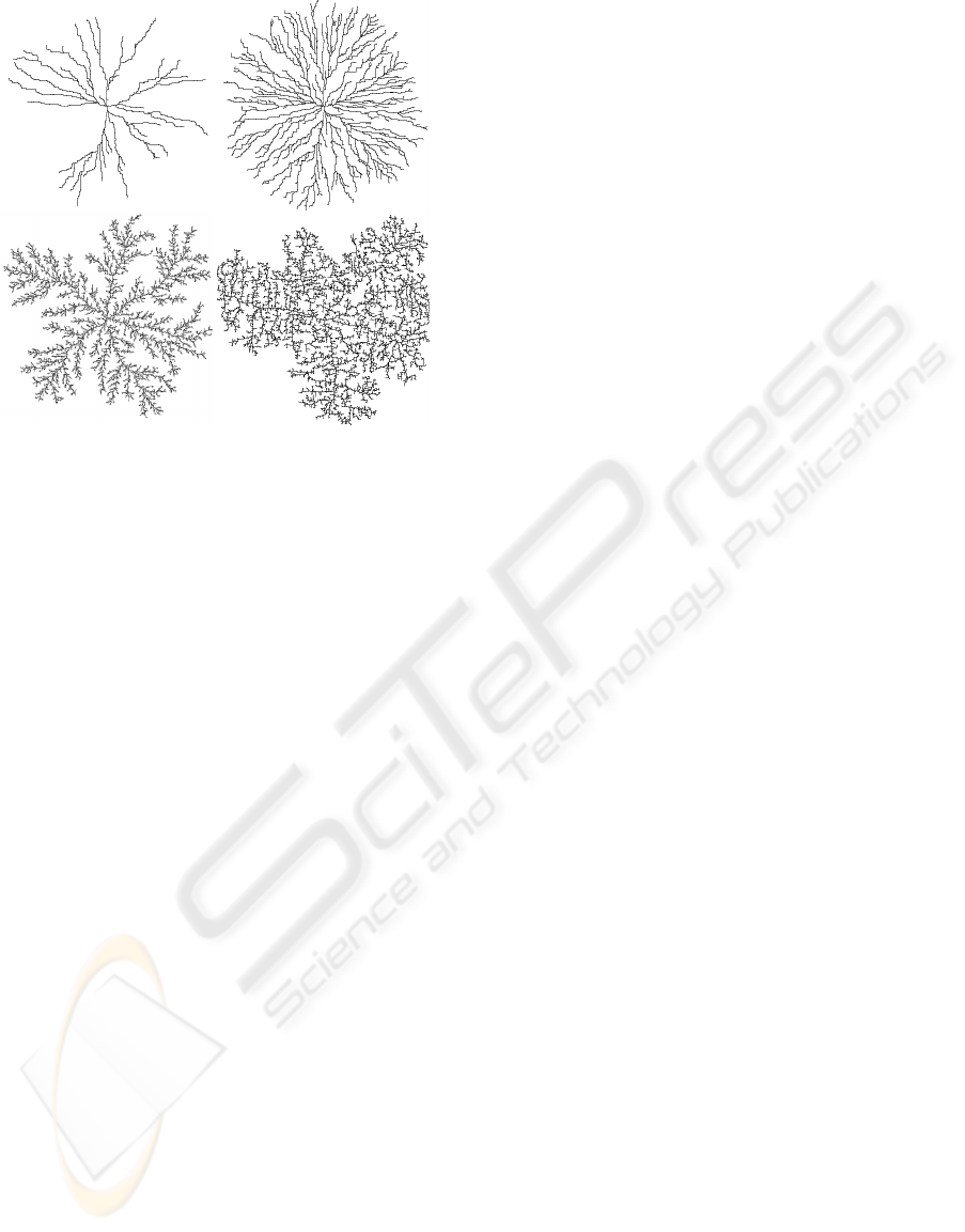
Figure 1: Above: simple dendrites, with few or many paths;
below: fractal dendrites, where new paths are repeatedly
placed in the vicinity of previously chosen paths.
with a summary of the contributions and pointers to
possible future work.
2 PREVIOUS WORK
Algorithms for procedural geometry have been de-
vised by computer graphics practitioners. Two algo-
rithms in particular, L-systems and diffusion-limited
aggregation, have seen considerable attention because
of their versatility and the quality of their results.
L-systems (Lindenmayer and Prusinkiewicz, 1990)
uses a replacement grammar to create strings which
can be interpreted as a variety of botanical forms,
particularly (though not exclusively) branching struc-
tures. Diffusion-limited aggregation (DLA) is an
algorithmic process capable of generating dendritic
forms akin to those seen in a number of natural ob-
jects, including lichens, crystals, neurons, and light-
ning (Bunde and Havlin, 1996). We are particu-
larly interested in DLA, owing both to the rich set of
phenomena which can be described by this method,
and to the irregularities in the branching structures;
we aspire to create dendrites with the same natu-
ral appearance. Other models for dendritic growth,
including viscous fingering (Ball, 2004), the Eden
model (Bunde and Havlin, 1996), and ad-hoc greedy
models (Gastner and Newman, 2006), have appeared
in the physics and biology literature.
Diffusion-limited aggregation has recently been
used in graphics to model lichens (Desbenoit et al.,
2004) and ice crystals (Kim and Lin, 2003; Kim et al.,
2004). Lightning (Kim and Lin, 2004) has been mod-
eled using the related dielectric breakdown model,
which describes another form of Laplacian growth.
These results are of high visual quality, although the
modeling process is time-consuming.
The brute-force algorithm for diffusion-limited
aggregation (Witten and Sander, 1981) is as follows.
Some initial sites in a lattice are set to “occupied”; the
remainder of the lattice nodes are unoccupied. A par-
ticle is released, at a great distance from any occupied
site, and undertakes a random walk until it reaches
some location adjacent to an occupied site. At that
point, the node where the particle is located becomes
occupied, and a new walker is released. The above
process is repeated, hundreds, thousands, or even mil-
lions of times. When a sufficient number of particles
have been placed, the resulting aggregation has a frac-
tal dendritic shape; the dendrites arise owing to the
greater likelihood of a particle encountering the tip of
a branch than a point along a branch.
L-systems is a parallel rewriting grammar that
takes an initial string (“axiom”) and repeatedly per-
forms applicable transformations on it. The final
string is an encoding of some object, often fractal; the
string is interpreted into geometry by mapping each
symbol in the string to some geometric primitive or
action. (A popular mapping is to have the symbols
represent “turtle movement”: move forward, move
backward, turn left, turn right).
Basic L-systems do not consider information
about the surroundings, since the interpretation into
geometry happens at the end of the process. While ba-
sic DLA alters the contents of the grid, other environ-
ment variables are not used in DLA simulation either.
For modeling interactions with the environment, open
L-systems (Mech and Prusinkiewicz, 1996) were de-
vised. While the previous environmentally-sensitive
L-systems (Prusinkiewicz et al., 1994) introduced
query symbols allowing information about the envi-
ronment to influence development, open L-systems
have a symbol in the grammar for two-way commu-
nication between the L-system and the environment.
The similar notion of open DLA has also been em-
ployed for lichen simulation (Desbenoit et al., 2004).
The main drawback to L-systems lies in the difficulty
of devising the system of replacement rules; the con-
nection between the rules and the resulting shapes can
be profoundly obscure.
3 ALGORITHM
Our algorithm involves finding a collection of paths
through a weighted graph. The graph is a regular lat-
GRAPP 2007 - International Conference on Computer Graphics Theory and Applications
30
tice filling the 2D or 3D space where the modeled ob-
ject is to exist; weights on the edges are chosen at
random. To create a dendritic form, we connect to-
gether multiple paths which share one endpoint, the
root of the dendrite. Our implementation performs a
breadth-first computation of path costs from the root
to all nodes in the lattice. The dendritic shape can ei-
ther be converted to geometry, directly (as lines) or by
taking an isosurface from a scalar field; or, the shape
can be visualized without the intermediate geometry,
in the case of 2D dendrites.
The method for creating dendrites operates as fol-
lows. A regular lattice is created, and the edges
of the lattice given weights from some distribu-
tion. We use four-connected lattices (six-connected in
3D) to conserve memory, but eight-connectivity (26-
connectivity) could be used to reduce lattice artifacts;
in this case non-orthogonal edges’ weights would
need to be scaled appropriately. We have found that a
uniform distribution of weights, say W = 1 + rhRi,
works well. In the preceding, we denote by W a
weight, and let hRi be a value chosen randomly from
the interval (0, 1); r is a parameter determining the
amount of fluctuation permitted in the weights. We
found a value of r around 10 to work well. Note that
with small r the resulting paths are close to Manhattan
paths (since the constant term dominates), while with
larger r the paths are more erratic (since the random
component is relatively more important).
We often perform breadth-first computation from
a more elaborate set of nodes than just a single root
node, and we need some terminology to refer to the
base nodes (those at distance zero); borrowing from
the implicit surfaces terminology, we call this set of
nodes the generators. The next stage in our algorithm
is to choose the generators for the dendrite. If the
generators are single disjoint nodes, each one will be-
come the root of a separate dendritic shape, but we
commonly choose connected sets of points, as de-
scribed shortly. Using breadth-first search, we pop-
ulate all nodes in the lattice with the costs of their
least-cost paths from the generators.
Next, we select a set of endpoints in the lattice.
The endpoints can be chosen randomly, determined
procedurally, or placed manually. In the examples
shown in this paper we placed endpoints almost ran-
domly; we used rejection sampling to prevent two
endpoints from appearing too near to one another.
With the endpoints chosen and the graph popu-
lated with distance values, we use a greedy algorithm
to find the least-cost path from each endpoint to the
nearest generator. The union of the paths thus ob-
tained is the dendrite. The overall construction pro-
cess is shown in Figure 2.
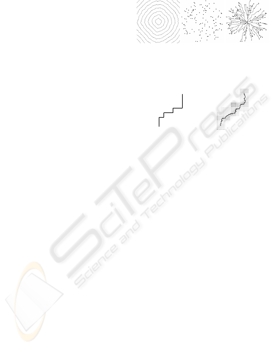
Figure 2: Plain dendrite construction process. Left: iso-
contours of distance values from central generator. Middle:
randomly placed endpoints. Right: dendrite arising from
planning paths from endpoints to central generator.
Figure 3: Left: a coarse path; the refined lattice will be
generated around it. Right: a new path computed inside the
refined lattice.
3.1 Path Refinement
Our method as described so far produces shapes with
resolution limited by the fixed resolution of the mesh.
However, there is a natural extension to an iterative
refinement approach: once the skeleton of the den-
drite has been created, or the shell of the object in the
case of a mesh from a segmentation, a new higher-
resolution lattice can be constructed in the region of
interest. This refinement process can be repeated if
desired. The basic idea is that a new sublattice is
built for each node in the dendrite; the sublattices are
hooked together to form a connected graph, where a
new pathfinding process can take place. Figure 3 il-
lustrates the process.
Pseudocode describing the refinement process for
a single path is shown in Figure 4; the process is re-
peated for each path in a dendrite. One advantage
of doing the refinement on a per-path basis is that
the high-resolution graphs are individually small, and
they are temporary, and hence memory usage is not
overly onerous. A side-by-side comparison between
a coarse dendrite and a refined dendrite is shown in
Figure 5. The refinement can also be applied to 3D
lattices to create a high-resolution 3D model.
MODELING DENDRITIC SHAPES - Using Path Planning
31
Input: a coarse path D consisting of m nodes.
Output: a refined path D
′
.
1. For each node in D, say N
i
, create a regular lat-
tice L
i
of size n × n. Assign positions to nodes in
L
i
relative to N
i
.
2. For i = 0 to m−2, stitch the lattices together by
adding edges between nodes in L
i
and L
i+1
. Call
the resulting graph G.
3. Perform a path planning task within G and re-
turn the result.
Figure 4: Pseudocode for refining a path.
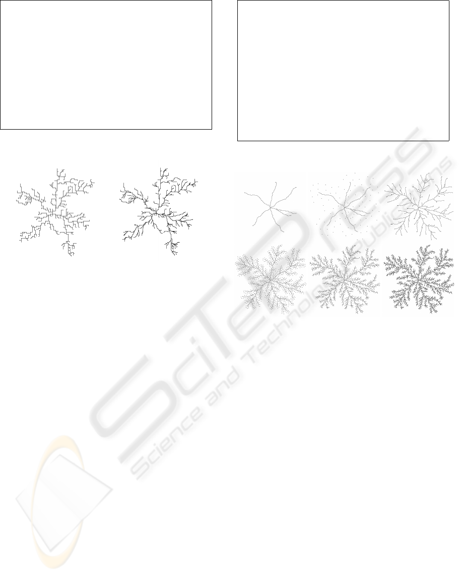
Figure 5: Left: a dendrite generated on a coarse graph.
Right: a refined version of the coarse dendrite.
3.2 Fractal Site Placement
A fractal dendrite can be created through an iterative
process involving repeatedly adding new endpoints,
and the corresponding paths, to an existing structure.
In the first iteration, the structure is a single root node.
In later iterations, we compute paths to the entire
structure obtained at the previous iteration.
At each iteration, we increase the number of end-
points to be placed by a branching factor β. At the
same time, the maximum distance from the generators
that each new endpoint is placed is reduced – divided
by a factor α, the attenuation factor. The process con-
tinues until the maximum distance is less than some
small value, say 2 pixels. Notice that the number of
iterations therefore depends on the attenuation factor;
a larger factor means that the maximum distance de-
cays to a value beneath the threshold more rapidly,
resulting in a sparser dendrite. Figure 7 gives a vi-
sualization of this process; pseudocode describing the
process is given in Figure 6. Images showing different
fractal dendrites are shown in Figure 8.
3.3 Converting to Geometry
We have two options for converting the description
of path locations to geometry. One option is to use
the paths nearly directly, and render each node on the
Input: weighted graph G, containing nodes N and
edges E; an initial generator Z; parameters α and
β; intial number of centres m; initial distance d.
Output: a list of nodes P on the fractal dendrite.
1. Set P to null; append Z to P.
2. Repeat the following while d > ε.
2A. Find m centres, at distances ≈ d from Z.
2B. Find a path from each centre to Z. Append
each path to P.
2C. Set m to m∗ β.
2D. Set d to d/α.
2E. Set Z to P.
Figure 6: Pseudocode for creating fractal dendrites.
Figure 7: A fractal dendrite (four iterations). Initially, we
have only a few branches, but successively more endpoints
are placed at successively smaller distance from the struc-
ture.
path as a simple geometric object, e.g., a sphere. This
approach has the advantage of extreme simplicity.
Another option is to create a distance field from
the structure and extract an isosurface from the field.
The distance field can be computed using the machin-
ery we already have in place: using the dendrite as the
generator, we make a pass of breadth-first search over
the lattice. The breadth-first search visits each node
in the lattice, populating it with the least-cost path
distance from the generators. The resulting distance
field can then be converted to geometry using an exist-
ing isosurface extraction algorithm such as marching
cubes. A visualization of the 2D isosurfaces from a
dendritic generator are shown in Figure 9.
3.4 Creating Solid Objects with Region
Marking
The same workflow used to create dendritic shapes
can also be used to generate irregular solid objects.
Specifying multiple disjoint nodes as generators, and
GRAPP 2007 - International Conference on Computer Graphics Theory and Applications
32
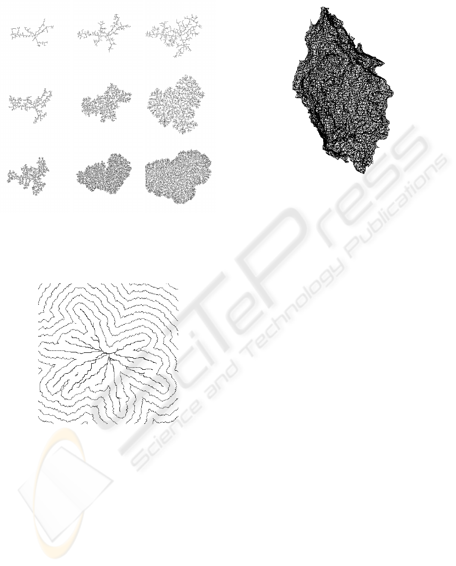
Figure 8: A few fractal dendrites, with different parameters
governing the branching factor and distance limit at each
iteration. Right to left: α = 2,1.5,1.2; top to bottom, β =
2,3,4. All dendrites were built with three iterations.
Figure 9: Two-dimensional isocontours from a dendritic
generator. A surface can be generated by taking one of these
contours.
keeping track during the breadth-first search process
of which site is nearest a given lattice node, has the ef-
fect of segmenting the volume. One region is created
for each generator node, consisting of all the points
nearest that node. A mesh marking the boundary of
one of these regions is shown in Figure 10.
The regions from the segmentation are locally ir-
regular but have a simple overall shape. We have re-
ferred to them as “rocks” because they resemble bro-
ken pieces of some hard and not necessarily homoge-
neous material.
Figure 10: “Rock” mesh from lattice segmentation.
4 RESULTS AND DISCUSSION
We next show some further results created by our
method, in the form of images and models. We have
already shown several examples of simple dendritic
forms, from Figure 1 onward. In this section we give
more elaborate models and provide some commen-
tary on the types of models that our approach can
generate. We give unadorned skeletal models and
meshes; more sophisticated rendering, including tex-
ture mapping, could improve the final images, but in
this paper we are focusing on the models themselves.
We can readily create dendritic forms, i.e., branch-
ing structures. Branching comes about in our model
owing to the use of a common graph for all pathing
queries: paths to nearby destinations will often share
the early portion of their route, so that a single path
appears to emerge from the source, branching when
the two previously overlapping paths deviate. The
same reasoning, plus the fact that we use a common
set of source nodes for all paths, means that the paths
will never cross one another. Given a consistent tie-
breaking mechanism, there is a unique path from the
source nodes to any node in the graph; hence, two
paths that meet do not cross, but rather share the same
path the rest of the way to the generators.
We have set out to imitate the dendritic forms of
DLA, and the results of this imitation are shown in
Figure 11. The two models are visually extremely
similar, although a detailed investigation would reveal
the limited nature of the path planned dendrite (it is
fractal only over the small range of scales explicitly
programmed in). However, to the unaided human eye
the structures look extremely similar; the pragmatic
difference is that the path planned dendrite took about
MODELING DENDRITIC SHAPES - Using Path Planning
33

Figure 11: Top: dendritic form generated by diffusion-
limited aggregation. Bottom: imitation of DLA with a path
planned fractal (4 iterations).
100 times less computer time to create.
We used our system to build a model of staghorn
coral, shown in Figure 12. The coral model was cre-
ated by manually placing endpoints in a 3D graph;
the points were not chosen to exactly duplicate the in-
put model, but to give a visually similar appearance,
i.e., the synthetic coral could plausibly have come
from the same underlying growth process. Despite the
small amount of information provided to the modeler
(only the endpoints of the branches were specified),
the synthetic coral model resembles the real coral
quite well. The synthetic image was rendered using
Pixie (pixie.sourceforge.net), with the high-frequency
structure (thorns) on the surface of the branches ob-
tained from a Renderman displacement shader.
Figure 13 demonstrates one way to exploit the
graph to give high-level control over the dendritic
Figure 12: Left: real coral. Right: coral generated using
path planning.
Figure 13: “Hello” written with dendrites.
shapes. In generating this figure, we created a sepa-
rate graph for each letter, and arranged the nodes of
the graph into the shape of the desired letter. The
resulting paths filled a portion of the space within
the graph, causing the letter to become visible. A
similar mechanism could be used to generate three-
dimensional forms, in a manner akin to the synthetic
topiaries of Prusinkiewicz et al. (Prusinkiewicz et al.,
1994). Our 2D result is comparable to the lichen-
writing of Desbenoit et al., who distributed seeds for
DLA in letter-shaped regions.
Competition for space is one of the phenomena
simulatable within the framework of open L-systems.
We can imitate this phenomenon within our frame-
work by placing multiple disjoint generators within
our graph and scattering endpoints nearby. An exam-
ple of competition is shown in the left of Figure 14.
Although the dendrites do not actually communicate
during the path planning process, the dendritic forms
appear to exhibit an avoidance behaviour.
A dendritic form akin to lightning is shown in the
GRAPP 2007 - International Conference on Computer Graphics Theory and Applications
34
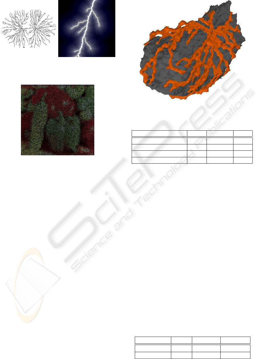
Figure 14: Left: competition for space on the part of two
lichens. Right: endpoint placement producing a shape re-
sembling lightning.
Figure 15: A mossy version of the peppers image.
right of Figure 14. For this 2D example, little needs
to be changed from the typical 2D dendrites we previ-
ously showed: the generator is a single node at the top
of the image, and we initially placed a small number
of endpoints at the bottom of the image, producing the
main lightning strokes. Subsequently, we added more
endpoints in the vicinity of the main strokes, with a
bias towards placing them lower in the image. This
approach can straightforwardly be extended to 3D by
using a 3D lattice.
The lightning example illustrates another control
handle our framework possesses: the endpoints of
the dendrite can be specified exactly. DLA can offer
control over the endpoints of the main branches (by
starting random walkers from the location the branch
should reach), but control over positions of secondary
branches is more difficult to achieve.
We can produce forms resembling moss by having
a plane or other surface as a generator, and comput-
ing paths to destinations near the surface. Figure 15
shows a large number of paths computed up from the
plane. In this example, paths are rendered as chains
of line segments with lighting given by the variant of
deep shadow maps (Lokovic and Veach, 2000) pro-
posed by Bertails et al. (Bertails et al., 2005), and the
colors of the paths taken from the peppers test image.
Hair or fur could be generated similarly.
Figure 16: Lichen on rock, both generated with our method.
Table 1: Table of model timing results.
Model lattice endpoints time
Simple dendrite 600
2
15 0.94 s
Fractal dendrite 512
2
8930 7.55 s
Coral (no refinement) 50
3
11 1.06 s
Coral (with refinement) 50
3
24 3.06 s
Figure 16 shows a lichen growing over a rock.
Both the lichen and the rock models were generated
using our method: the rock mesh by segmenting a
lattice as described in section 3.4, and the lichen by
placing both the path endpoints and the dendrite gen-
erator on the rock and forbidding paths to enter inte-
rior rock nodes. Notice, therefore, that the modelled
lichen is able to leave the surface of the rock briefly
before returning; had we so chosen, we could easily
have constrained the lichen to the rock face, simply
by considering only nodes on the rock boundary. The
rock and lichen models in Figure 16 demonstrate the
flexibility of our approach, with two quite different
models generated by the same underlying process.
Table 1 and Table 2 show timing results for our
method. The figures in Table 1 give times for model
construction; these models were either shown directly
or were rendered using spheres. Timing results in Ta-
ble 1 are given for a 1.8GHz P4 with 512 MB RAM.
Table 2 gives timing figures for the models rendered
using extracted isosurfaces; here, “modeling” is the
Table 2: Timing data for implicit models.
Model lattice modeling isosurface
Rock model 128
3
8.0 s 3.2 s
Rock+lichen 128
3
9.5 s 7.4 s
MODELING DENDRITIC SHAPES - Using Path Planning
35

time needed to create the lattice, produce the den-
dritic shape, and compute the distance field for that
shape, and “isosurface” is the time needed for march-
ing cubes to extract the isosurface from the distance
field. In table 2, timing figures are given with respect
to a 3.2GHz P4 with 1GB RAM.
For 2D dendrites, the sub-one second modeling
time can be considered interactive, so that different
parameter settings can be experimented with live. The
3D modeling times, albeit on a somewhat coarser
grid, are nonetheless only around 10 seconds; for
comparison, the lightning simulations of Kim and Lin
require hours, and the ice simulations (in 2D) still re-
quire at least a few minutes. Desbenoit et al. (Des-
benoit et al., 2004) give times ranging from 1 second
to nearly 500 seconds, depending on the complexity
of the generated lichen. The DLA image shown in
Figure 11 was generated at a resolution of 500× 500
with 25000 particles; the basic random walker algo-
rithm was used on a 3.2GHz P4 and required about
7.5 minutes to complete.
5 CONCLUSIONS
We have presented a fast, simple method for generat-
ing dendritic forms. Because path planning has been
well studied in computer science, many standard al-
gorithms exist and should be familiar to computer
graphics practitioners; in consequence, our algorithm
is easy to implement. The path planning formulation
creates dendrites extremely quickly: less than a sec-
ond for simple structures, and less than 10 seconds for
complex fractal and 3D structures. Orders of magni-
tude more time are required for DLA and other re-
ported systems for creating dendritic shapes.
The range of natural objects expressible as den-
dritic forms is great. In addition to dendrites, the path
planning approach can generate irregular solid objects
by segmenting an input mesh. The versatility of den-
drites, combined with the ability to generate irregu-
lar solid models, gives our method potentially wide
applicability. Unlike L-systems, the path planning
framework is not very mature, and much remains to
be discovered. For example, future work can address
the endpoint placement process, perhaps by distribut-
ing them procedurally in a more sophisticated way.
In this paper, we have given a broad overview of
the dendritic shapes our method can generate. One
avenue for future work is to narrow in on specific phe-
nomena: lightning, trees, and lichens have long been
of interest in computer graphics, and we find moss a
particularly intriguing direction.
ACKNOWLEDGEMENTS
Thanks to Peter O’Donovan for the mossy peppers
image. This work was supported by NSERC RGPIN
299070-04.
REFERENCES
Ball, P. (2004). The Self-Made Tapestry: Pattern Formation
in Nature. Oxford University Press.
Bertails, F., M
´
enier, C., and Cani, M.-P. (2005). A practi-
cal self-shadowing algorithm for interactive hair anim
ations. In Graphics Interface 2005.
Bunde, A. and Havlin, S. (1996). Fractals and Disordered
Systems. Springer-Verlag, Berlin.
Desbenoit, B., Galin, E., and Akkouche, S. (2004). Simulat-
ing and modeling lichen growth. Computer Graphics
Forum, 23(3):341–350.
Gastner, M. and Newman, M. (2006). Shape and efficiency
in spatial distribution networks. Journal of Statistical
Mechanics, 01(P01015).
Kim, T., Henson, M., and Lin, M. C. (2004). A hybrid algo-
rithm for modeling ice formation. In 2004 ACM SIG-
GRAPH/Eurographics symposium on Computer ani-
mation, pages 305–314, New York, NY, USA. ACM
Press.
Kim, T. and Lin, M. C. (2003). Visual simula-
tion of ice crystal growth. In 2003 ACM SIG-
GRAPH/Eurographics symposium on Computer ani-
mation, pages 86–97. Eurographics Association.
Kim, T. and Lin, M. C. (2004). Physically based anima-
tion and rendering of lightning. In Pacific Conference
on Computer Graphics and Applications 2004, pages
267–275.
Lindenmayer, A. and Prusinkiewicz, P. (1990). The Algo-
rithmic Beauty of Plants. Springer-Verlag, New York.
Lokovic, T. and Veach, E. (2000). Deep shadow maps.
In Proceedings of SIGGRAPH 2000, pages 385–392,
New York, NY, USA. ACM Press.
Mech, R. and Prusinkiewicz, P. (1996). Visual models of
plants interacting with their environment. In Proceed-
ings of SIGGRAPH 1996, pages 397–410, New York,
NY, USA. ACM Press.
Prusinkiewicz, P., James, M., and Mech, R. (1994). Syn-
thetic topiary. In Proceedings of SIGGRAPH 1994,
volume 28, pages 351–358.
Winston, P. (1992). Artificial Intelligence. Addison-Wesley
Publishing Company, Reading, MA, USA.
Witten, T. and Sander, L. (1981). Diffusion-limited aggre-
gation, a kinetic critical phenomenon. Physical Re-
view Letters, 47(19):1400–1403.
GRAPP 2007 - International Conference on Computer Graphics Theory and Applications
36
