
A HYBRID BACKWARD-FORWARD METHOD FOR
INTERACTIVE REFLECTIONS
Chunhui Mei, Voicu Popescu and Elisha Sacks
Computer Science Department, Purdue University, 305 N University Street, West-Lafayette, USA
Keywords: Reflection rendering, interactive frame rates, projection, ray-tracing, k-d tree, continuous 3-ray camera.
Abstract: We propose a two phase hybrid reflection rendering method based on approximating the reflected rays with
a set of simple cameras modeled as continuous 3-ray cameras. In the first, "backward", phase, the view
volume of each simple camera is intersected with a hierarchical subdivision of the scene to find the
geometry it encompasses. In the second, "forward", phase the geometry is projected with the simple camera.
Since the shape and topology of reflected triangles is complex, point based rendering is adopted to
reconstruct the reflection. The hybrid method is efficient since it combines advantages of backward and
forward techniques: there are two orders of magnitude fewer simple cameras than reflected rays, the
hierarchical scene subdivision implements fast view volume culling for each of the simple cameras, and the
reflection piece corresponding to each simple camera is computed efficiently in feed-forward fashion.
1 INTRODUCTION
Reflective surfaces are the first to draw the attention
of a user that visually explores a 3D scene. In
addition to intriguing aesthetic quality, reflections
bring concrete contributions to the user’s
understanding of the scene, revealing surface
properties and the relative position of objects.
Unfortunately, rendering reflections is challenging.
The difficulty comes from the fact that every
reflective surface is essentially a portal into a world
that is potentially more complex than the directly
observed scene. In the reflected scene the rules of
image formation are substantially more complex
than those in the case of single perspective: a 3D
point can have more than one projection, straight
lines project to curves, some surfaces are magnified
and others minified to the extreme. Much work has
been devoted to rendering reflections, but no
technique exists that renders accurate reflections on
general surfaces at interactive rates. We group prior
techniques in four categories.
Ray tracing techniques search for scene
geometry along desired view and reflected rays.
Such techniques produce breathtaking reflections,
but the backward mapping from the output pixels to
input geometry is inefficient, and ray tracing is not
the approach of choice in interactive graphics. The
feed-forward graphics pipeline, with the main stages
of projection and rasterization, has proven to be the
best suited for computer graphics applications where
efficiency is at a premium. However, rendering
reflections with the feed-forward approach requires
solving the difficult problem of projecting reflected
vertices. For a general reflector surface there is no
closed form solution to the problem of finding the
image plane location of a reflected 3D point. Feed-
forward techniques were developed for planar and
convex reflectors, cases when the problem of
projecting reflected vertices is tractable.
Reflected-scene approximation techniques
intersect reflected rays with a simpler version of the
scene, in the interest of efficiency. A prime example
is environment mapped reflections, where the
reflected scene is replaced with a distant color
panorama. Less drastic approaches simplify the
scene using billboards or depth map impostors. The
disadvantages of the approach are loss of accuracy
and additional modeling burden.
Image-based rendering (IBR) techniques employ
pre-acquired or pre-rendered reference reflections to
reconstruct the reflections in the desired view. The
forte of these techniques is the visual realism
inherited from photographs or from reference
images elaborately rendered offline. Disadvantages
include limited support for highly reflective
284
Mei C., Popescu V. and Sacks E. (2007).
A HYBRID BACKWARD-FORWARD METHOD FOR INTERACTIVE REFLECTIONS.
In Proceedings of the Second International Conference on Computer Graphics Theory and Applications - GM/R, pages 284-292
DOI: 10.5220/0002076802840292
Copyright
c
SciTePress
surfaces, which require a high sampling rate, and
limited support for dynamic scenes, where reference
reflections become obsolete.
In this paper we describe a hybrid technique that
combines elements characteristic to ray tracing with
feed-forward rendering. The desired view and the
reflectors in the scene define a set of reflected rays
for each frame. Depending on frame resolution and
on how much of the frame is covered by reflectors,
the set of reflected rays can contain hundreds of
thousands of rays. Our technique approximates these
rays with a few thousand simple cameras by taking
advantage of the local coherence exhibited by the
ray set. A simple camera is an atomic camera that
has an efficient projection function. A simple
camera could be modeled as a planar pinhole
camera, but the reflected rays are not concurrent and
forcing them through a pinhole introduces large
errors. We use instead a continuous 3-ray camera
(C3RC) (Popescu et al., 2006), a non-pinhole model
that interpolates between 3 given rays. The C3RC is
a generalization of the general linear camera (Yu
and McMillan, 2004), with the advantage of
projection continuity across shared edges of adjacent
cameras.
In a first phase, the view volume of each C3RC
is intersected with the scene to find the geometry it
encompasses. This backward mapping phase is
common to ray tracing techniques, and we accelerate
it using a kd-tree (Bentley, 1979) scene subdivision.
The kd-tree ensures efficient frustum culling for the
C3RCs.
In a second phase, the reflection is computed in
feed-forward fashion. Each simple camera renders
the geometry inside its view volume to produce a
piece of the reflection. Although the reflected
objects are modeled with triangle meshes,
conventional vertex projection followed by projected
triangle rasterization is complicated by several
factors. First, a vertex could have more than one
projection, even within a single C3RC. Second, the
view volume of the C3RC is complex and triangle
clipping is expensive. Third, the edges of the
projected triangles are curved, which requires
subdividing the triangle such that its projected edges
can be acceptably approximated with straight
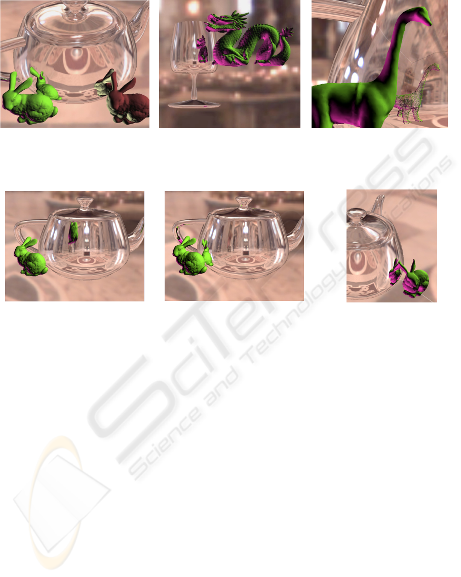
Figure 1: Objects reflected with our technique. The reflector complexity [thousands of triangles], reflected objects total
complexity [thousands of vertices], and average frame rate [fps] are 4, 74, and 5 for the left image, and 2, 100, and 4 for the
middle image. The reflection of the objects is rendered in point-based fashion, as illustrated in the right image.
Figure 2: Comparison to environment mapping. Environment mapping (left) is inaccurate for objects close to the reflector.
Our technique (middle) produces correct reflections even if the object intersects the reflector (right).
A HYBRID BACKWARD-FORWARD METHOD FOR INTERACTIVE REFLECTIONS
285

segments. A point-based representation of the
reflected objects bypasses these challenges. As a
preprocess we sample the reflected geometry and
store the points in the kd-tree. At run time the points
are splatted using the C3RC to form the reflection.
The two phase backward-forward approach
produces quality reflections at interactive rates, see
Figure 1, 2, and 5, and the accompanying video. The
method has an efficiency advantage over ray tracing
because there are two orders of magnitude fewer
C3RCs than there are reflected rays, and because the
geometry within the view volume of a C3RC is
processed efficiently in feed-forward fashion.
Compared to a naïve feed-forward approach that
renders each triangle with each of the C3RCs, our
method benefits from the view volume culling
provided by the hierarchical scene subdivision.
2 PRIOR WORK
Image-based rendering
Light fields (Levoy and Hanrahan, 1996), are the
most powerful IBR primitive and they naturally
support reflections. Light fields can be used to
render reflections in one of several ways. The light
field can directly provide the desired view ray—it
does not matter whether the ray was reflected one or
several times on its path from the light source to the
eye. Another approach is to use a surface light field
(Miller, 1998), (Wood et al., 2000) attached to the
reflector in which to lookup the desired view rays
that intersect the reflector. A third possibility is to
surround the reflector with a conventionally
parameterized light field and to look up the reflected
ray, a technique called light field mapping (Yu and
McMillan, 2005). A fourth approach is based on
decoupling reflector properties from illumination.
This is achieved with a light field that maps incident
rays to reflected rays (Heidrich, 1999), or to a set of
radiance environment maps (Cabral and Olano,
1999).
Several techniques have been developed for
rendering reflective surfaces from 2D ray databases,
such as view dependent texture mapping (Debevec
et al., 1998), or parameterized environment maps
(Hakura, 2001). A disadvantage common to all IBR
reflection rendering techniques is the lack of support
for dynamic scenes: if the reflecting or reflected
objects move, or if the lighting conditions change,
the reference rays become obsolete. A second
disadvantage is limited support for highly reflective,
mirror-like surfaces, which require a high sampling
rate and generate impractically large ray databases.
Feed-forward methods
These methods set out to solve the reflected-point
projection problem, in order to make reflection
rendering tractable in the context of the feed-forward
pipeline. Projection is simple in the case of planar
reflectors (Diefenbach, 1996), but it does not have a
closed form solution in the case of curved reflectors.
Explosion maps (Ofek and Rappoport, 1998) and
sample-based cameras (Popescu et al., 2006) tackle
the projection problem for curved reflectors.
Explosion maps need to be recomputed for every
frame, which is inefficient, and the projection of
reflected vertices is approximate.
Sample-based cameras are similar to our method,
so we describe them in more detail. For each frame,
the set of reflected rays is partitioned recursively in
sets that are small enough such that they can be
approximated well with a planar pinhole camera. An
approximation is considered acceptable if the
projection error is below a user specified threshold,
typically 1 to 5 pixels. The planar pinhole cameras
are stored at the leafs of a binary space partitioning
tree (BSP), which is called a sample based camera
(SBC). The reflection is rendered with the SBC by
projecting scene vertices and then by rasterizing the
resulting triangles in pure feed-forward fashion. In
order to avoid excessive redundancy during the BSP
construction and inefficiency during projection, the
view frusta of the planar pinhole cameras need to be
disjoint. This condition is only satisfied by convex
reflectors, which is a severe limitation.
Our method does not require the view frusta of
the simple cameras (C3RCs in our case, planar
pinhole cameras in the case of SBCs) to be disjoint,
since, instead of partitioning the view frusta, we
partition the scene to be reflected. The SBC is a
compound camera which finds the simple camera
that contains a given point in logarithmic time. The
first phase of our method on the other hand is similar
to ray tracing in that it iterates over all simple
cameras and finds the geometry each of them sees in
logarithmic time. The advantage is lifting the
limiting condition that the reflector be convex.
Ray tracing
Ray tracing (Whitted, 1980), (Glassner, 1989) is a
general rendering technique that produces high
quality reflections. In the context of interactive
graphics, the challenge is performance. A wide
range of acceleration schemes have been proposed,
and ray tracing has been shown to run at interactive
rates on shared memory parallel computers (Parker,
1999), on special hardware (Hall, 2001), on a single
CPU (Wald, 2001), (Wald et al., 2001), (Reshetov et
GRAPP 2007 - International Conference on Computer Graphics Theory and Applications
286

al., 2005), and on GPUs (Purcell et al., 2002), (Carr
et al., 2002), (Weiskopf et al., 2004). At least for the
foreseeable future, GPUs will remain a primarily
feed-forward rendering engine. Therefore,
techniques like ours that attempt to cast the problem
of reflections in terms suitable for feed-forward
rendering will continue to best leverage GPUs.
Reflected-scene approximation methods
First order reflected rays can be easily computed
with the feed-forward graphics pipeline: the reflector
is processed like any geometry and per-pixel
reflected rays are computed using per-pixel normals.
Per-pixel normals are computed by interpolating
vertex normals, by perturbing interpolated normals
according to a bump map, or by looking up a normal
map. The problem is to intersect the scene with the
reflected ray. Several techniques solve this problem
by approximating the reflected scene. Environment
mapping (Blinn and Newell, 1976), (Greene, 1986)
is the classic example.
The reflected scene can be modeled with layered
depth images (LDIs) (Shade et al., 1998), and,
although ray tracing LDIs is less expensive than ray
tracing the entire scene, performance remains an
issue (Lischinski and Rappoport, 1998). A more
efficient method models the reflected scene with a
sphere of size comparable to size of the environment
(Bjorke, 2004). The disadvantage is that the sphere
is a crude approximation of the environment, which
translates in reflection inaccuracy. A cube map with
per-texel depth provides a tighter reflected scene
approximation (Szirmay-Kalos et al., 2005).
However, the impostor-ray intersection algorithm
makes drastic simplifying assumptions precluding
complex scenes.
3 ALGORITHM OVERVIEW
Given a scene of reflectors and diffuse nearby
objects, the algorithm proceeds as follows.
3.1 Preprocessing
In order to support point-based rendering of the
reflection, the diffuse geometry is pre-sampled
uniformly. One of the challenges of point-based
rendering is hole-free reconstruction. One advantage
specific to reflections is that the distance from the
reflected object to the reflector places a lower bound
on the distance between the viewpoint and the point-
based rendered object.
Another advantage is that curved reflectors
typically minify the reflected object, which reduces
the required sampling rate. Even for concave
reflectors there is only a relatively small region of
space where rays are condensed. After the quasi-
convergence region rays diverge again. When a
reflected object is placed in the quasi-convergence
region, point-base reconstruction is challenging.
Front surface opacity can be maintained by
increasing the splat size during rendering. For the
examples shown in this paper it was easy to find
sampling rates that do not leave holes even for small
splat sizes, which ensures a quality reconstruction.
Once the diffuse triangle meshes are sampled,
reflections are rendered from the set of diffuse
points and the reflector triangle meshes with the
following run-time algorithm.
3.2 Run-time
For each frame
Build a kd-tree K for the diffuse point set (Section 4).
Construct C3RCs for each triangle of each reflector
mesh (Section 5).
For each C3RC C
Intersect view volume V of C into K to find the
set S of leafs of K that intersect V (Section 5.2).
For each leaf L in S (Section 6)
For each point P in L
Project P with C to P’ (Section 5.1)
Rasterize P’
4 KD-TREE CONSTRUCTION
We use a standard kd-tree to organize the diffuse
point set hierarchically. The termination criterion for
the recursive construction of the tree is reaching a
minimum number of points or a minimum size for
the leaf node. For simple diffuse objects the kd-tree
construction is fast enough to be performed on the
fly. Higher complexity diffuse point sets are
partitioned off-line. A kd-tree remains valid under
rigid body transformations.
5 CONTINUOUS 3-RAY CAMERA
C3RCs are the mechanism for taking advantage of
reflected ray coherence. A C3RC is built for each
reflector triangle, replacing the reflected rays
generated by that triangle. A C3RC interpolates
A HYBRID BACKWARD-FORWARD METHOD FOR INTERACTIVE REFLECTIONS
287
between 3 construction rays of unit length (Popescu
et al., 2006). The 3 rays are the reflected rays at the
vertices of the reflector triangle (Figure 3). Given
the normal at the vertex and the desired viewpoint,
the reflected ray can be easily computed. The C3RC
image plane is defined by the tails of the 3
construction rays, thus it coincides with the reflector
triangle that generated the C3RC. The C3RC model
is based on the general linear camera model (Yu and
McMillan, 2004), but they have the important
advantage of projection continuity across an edge
shared by two adjacent C3RCs. In our algorithm
C3RCs are called upon to perform two basic
operations: 3D point projection and box-view
volume intersection.
5.1 C3RC Projection
The C3RC projection equation is cubic (Popescu et
al., 2006) so a C3RC can have up to 3 real
projections. We analyzed C3RC projection in detail
to understand if there are cases when more than one
of these real projections falls inside the triangular
image frame (base) of the C3RC. Such a multiple
projection occurs if two or more rays intersect, so a
natural approach is to solve the system of equations
that searches for a point on two rays. Intersecting
two rays yields a fourth order equation. Although
closed form solutions exist, it is difficult to decide
whether a solution is possible for rays inside the
triangular image frame, which has to be tested with
inequations on the barycentric coefficients of the
rays.
A simpler approach that confirmed the existence
of multiple projections is to describe the view
volume with a sweeping triangle that cuts equal
segments on the construction rays (Figure 4, left).
The first sweeping triangle is the C3RC base itself.
If a point Q projects inside the base of the C3RC at
barycentric coordinates a, b, and (1-a-b), then there
is a position T of the sweeping triangle that contains
Q at barycentric coordinates a, b, and (1-a-b). If Q is
to have two valid projections, there will be two
positions of the sweeping triangle that contain Q.
Figure 4, right shows two intersecting instances of
the sweeping triangle. Any point on the intersection
segment has at least two valid projections.
The sweeping triangle does not self-intersect for
divergent C3RCs, nor does it intersect for all
convergent-then-divergent C3RCs like the one seen
in Figure 4. We have established a method for
deciding whether a C3RC can have multiple
projections based on the observation that the
sweeping triangle cannot self-intersect while all 3
construction rays are on the same side of the
triangle’s plane. Initially all construction rays are on
the same side of the base. A construction ray
switches sidedness when it is contained in the plane
of the sweeping triangle.
The sweeping triangle positions where it contains
one of the construction rays are found by solving a
quadratic equation. If none of three equations has a
solution, the construction rays remain on the same
side of the sweeping triangle and no multiple
projections can occur. If one or more equations have
solutions, the view volume sub-region where
multiple projections can occur is defined by
sweeping parameter values in intervals where two
construction rays are on one side, and one if on the
opposite side of the sweeping triangle. For the
example shown in Figure 4, right, multiple-
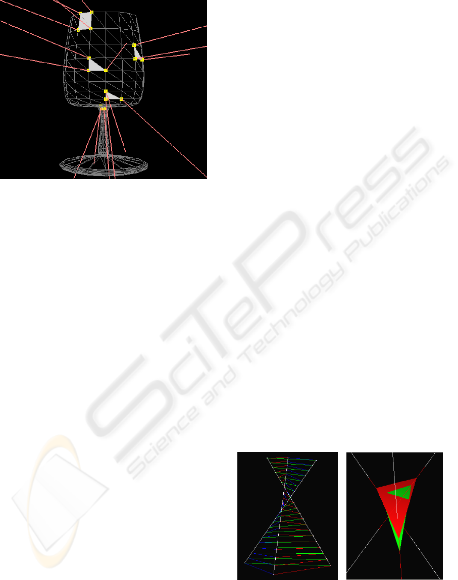
Figure 3: Visualization of sample C3RCs built for a glass
shaped reflector. The reflector triangles that define a C3RC
are shown in gray. The C3RC construction rays are shown
in red.
Figure 4: Sweeping triangle visualization of C3RC view
volume (left) and self-intersection of sweeping triangle
(right).
GRAPP 2007 - International Conference on Computer Graphics Theory and Applications
288
projections can occur when the sweeping triangle
intersects the construction rays inside the red
segments, which correspond to [0.98, 1.49].
5.2 Box-view Volume Intersection
During the “backward” phase the view volume of
each C3RC is intersected with the kd-tree to quickly
find the diffuse points inside visible to the C3RC.
For this one needs to decide whether a kd-tree node
(a box) does or does not intersect the view frustum.
A box clearly does not intersect a C3RC frustum if
both conditions below are met:
1. The box is not completely inside the frustum.
2. None of the 6 faces of the box intersects any
of the 3 side walls of the C3RC frustum.
Testing whether the first condition is satisfied is
simply done by testing whether an arbitrary box
corner does not have a valid projection.
To test for the second condition, we define the
side wall corresponding to base edge (v
1
, v
2
) of a
C3RC with the following parametric surface
)()(
)())(1(),(
121121
22111
dddvvv
dvdvS
−++−+=
++
+
−=
λαλα
λ
α
λ
α
λ
α
where 0 <= α <=1, and d
1
and d
2
are the
directions of the rays through base vertices v
1
and v
2
.
S
1
is intersected with a planar face of the box with
corner point o
1
and normal n
1
by solving the
equation
0)(
11
=− nop
to find
11211
11211
)(
)(
nddnd
nvvnv
−+
−+
−=
α
α
λ
Substituting λ back into the equation of S
1
, the
intersection between the box face and the frustum
side wall is determined as a parametric curve p(α)
))((
)(
)(
)()(
121
11211
11211
121
ddd
nddnd
nvvnv
vvvp
−+
−+
−+
−
−+=
α
α
α
α
α
The curve p(α) is intersected with the four
segments defining the face frame, to determine
whether the side wall intersects the box plane inside
the face. Each intersection implies solving a
quadratic equation.
As always, the box–view frustum intersection is
over conservative for the purpose of occlusion
culling since the box is assumed to be completely
filled with payload geometry. The efficiency of the
occlusion culling is analyzed in the results section.
6 FEED-FORWARD PHASE
When a kd-tree leaf intersects the view volume of
the current C3RC, the points contained by the leaf
are projected with a GPU vertex program.
Unfortunately the GPU programming framework
does not support issuing multiple fragments per
vertex, so multiple projections are not supported.
The projected vertices are rasterized as square points
of fixed size (1 or 2 pixels). The reflected scene is
three dimensional and proper visibility sorting needs
to be enforced. When two points land on the same
pixel, the one closer to the reflector surface should
win. This is implemented by pushing back a
projected point along its desired view ray, similarly
to the visibility enforcing mechanism described for
sample-based cameras (Popescu et al., 2006). The
push back amount equals the distance from the
original diffuse point to the reflector surface, which
is given by the distance to the C3RC image plane.
The point-based approach was chosen to avoid
the difficulties of reflecting triangle meshes.
Consider a diffuse mesh of triangles. Each vertex
can have 0 or more projections. The multiple
projections can originate from the same C3RC, and,
more frequently, from different C3RCs. Before
rasterization can begin, one needs to examine the
projections of the 3 vertices of a given triangle in
order to form projected triangles. We have not found
a reliable way of grouping vertex projections in
projected triangles. Cases when the 3 vertices have a
different number of projections or when the
projections cannot be easily separated in clusters of
triples remain challenging. Moreover, even if the
grouping succeeds, conventional rasterization
assumes that the edges of the projected triangle are
straight, which holds only for small triangles or flat
reflectors. The approximation error has to be
controlled by subdividing the diffuse geometry,
which converges to the point-based approach.
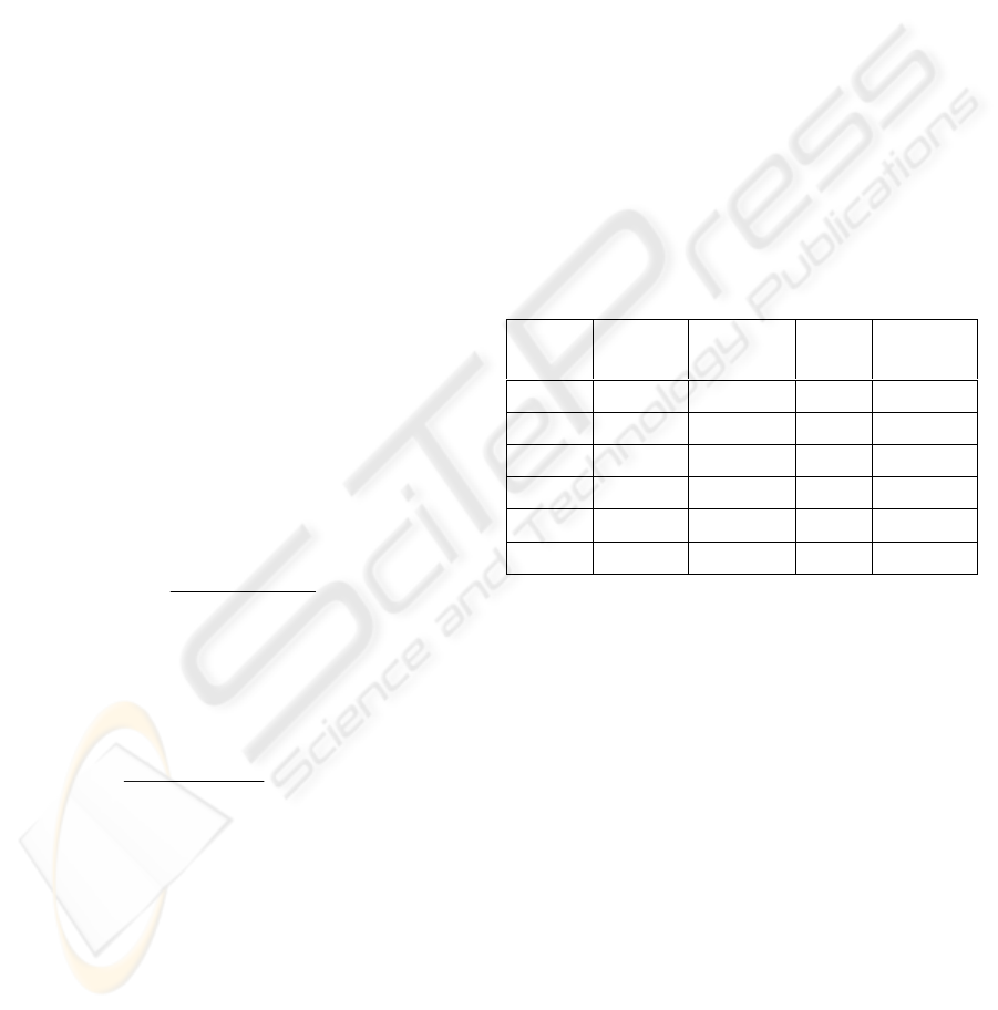
Table 1: Kd-tree construction performance.
Scene
Points
x1,000
Constr.
time [ms]
Avg.
depth
Vertices
per leaf
Statue0 543 577 7.4 122
Dragon0 437 533 7.2 121
Bunny0 147 190 6.1 121
Dragon1 100 95 5.7 122
Bunny1 37 25 4.7 121
Dinosaur 10 6 3.4 123
A HYBRID BACKWARD-FORWARD METHOD FOR INTERACTIVE REFLECTIONS
289
A possible way for bypassing the difficulty of
forming reflected triangles is to work within one
C3RC at a time and to clip triangles that extend
outside the view volume of the C3RC. Since the side
walls of the C3RC are not planar, clipping a triangle
is expensive, and the resulting shape is complex,
possibly disconnected. Even a triangle completely
contained in the view volume of a C3RC can have a
complex projection if it crosses the sub-regions
where multiple projections occur.
7 RESULTS
We have tested the hybrid reflection rendering
method on several scenes with good results (Figures
1, 2, and 5, and accompanying video). The
background reflection is first rendered by
environment mapping and then the reflection of the
(synthetic) objects near the reflector is computed
with our method.
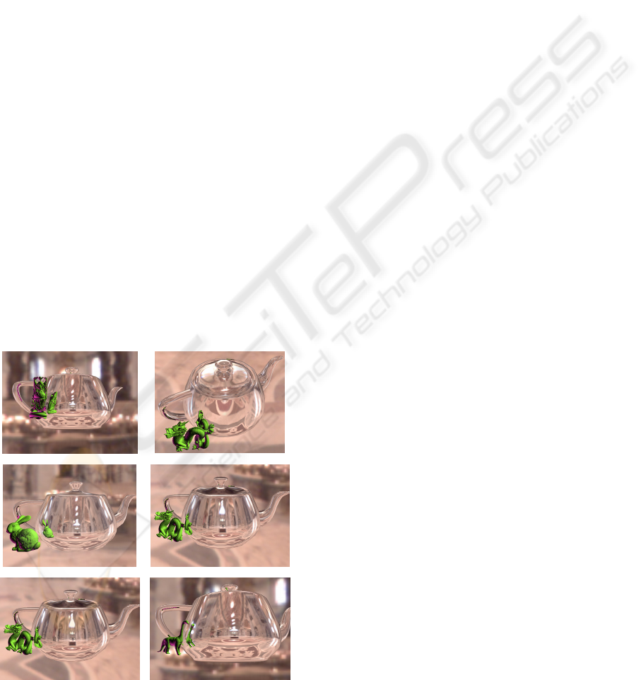
We have quantified performance for 6 test scenes
with variable diffuse geometry complexity. Images
of the 6 scenes are shown in row major order in
Figure 6. The same 4,000 triangle teapot is used as
reflector. All timing data reported in this paper was
measured on a 3GB 3.4GHz Pentium 4 Xeon PC
with a Quadro FX 3400 Nvidia graphics card.
The performance numbers of the kd-tree
construction are given Table 1. For small point sets
the kd-tree can be constructed on the fly. Rigid body
transformations of the diffuse object do not require
re-computing the kd-tree. The powerful eight-way
recursion makes the average tree depths and
numbers of points per leaf small.
The average hardware projection performance is
3.4 million vertices per second. The performance of
each of the two phases of reflection rendering is
given in Table 2 for each of the 6 test scenes. A
frame rate of 4 fps or better is obtained on all but the
two most complex diffuse scenes. Appropriate
parameters need to be chosen in the kd-tree
construction to balance the computation burden
between software culling and hardware projection. A
deep kd-tree and small leaf nodes accelerate
projection by increasing the ratio of valid projections
at the expense of slowing down view volume
culling. On the other hand a shallow tree and large
leafs reduce the culling effort at the expense of a
large number of unnecessary projections. The table
shows that for our system a good balance between
the two phases was obtained for a ratio of valid
projections of about 20%.
The performance of the method depends on the
complexity of the reflector in two ways. The number
of C3RCs equals the number of reflector triangles,
so the number of times the two rendering phases are
executed is linear in the number of reflector
triangles. The reflector shape complexity also
greatly influences performance. High curvatures
generate C3RCs with wide open view volumes,
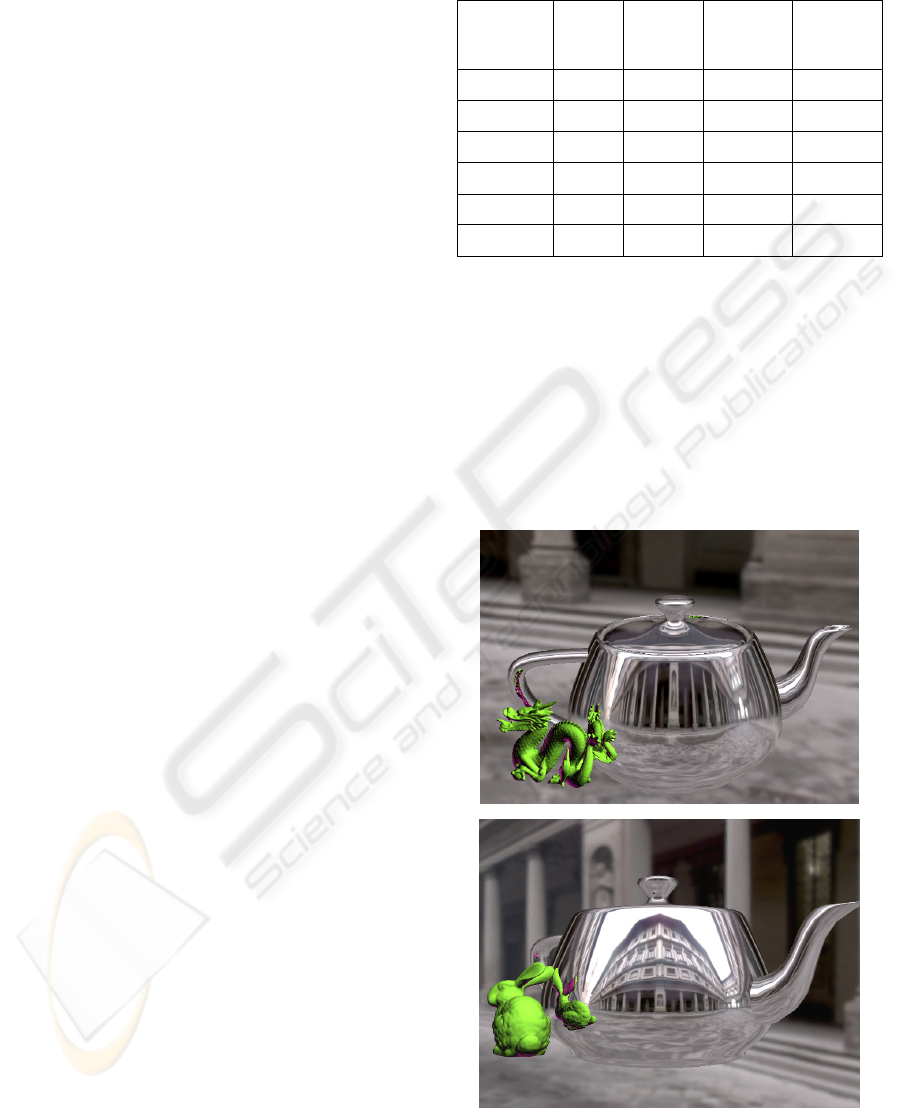
Table 2: Reflection rendering performance.
Scene
Total
time [ms]
Culling
[ms]
Projection
[ms]
Valid proj.
[%]
Statue0 650 304 346 21
Dragon0 588 273 315 20
Bunny0 264 136 128 19
Dragon1 250 134 116 20
Bunny1 121 63 58 19%
Dinosaur 48 25 23 19%
Figure 5: Reflections of dragon and bunny rendered with
our method over an environment mapped background.
GRAPP 2007 - International Conference on Computer Graphics Theory and Applications
290
which project a large number of points. For the
teapot for example, the handle, spout, and lid knob
project almost every point. Consequently most
points have on average 4 projections. Since the knob
is small in screen space, it should be rendered with
environment mapping.
8 CONCLUSIONS
Hybrid backward-forward reflection rendering
produces good results at interactive frame rates. The
versatility of points was leveraged to overcome
difficulties that arise in rendering reflected meshes.
This paper also furthers the understanding of
continuous 3-ray cameras which are important
infrastructure for applications beyond reflections.
Compared to ray-tracing, our technique is faster
if forward rendering of the geometry inside the
C3RC view volume is faster than ray tracing the
same geometry. This is the case if the reflector
triangle covers sufficient pixels in screen space. If
the reflector triangle covers only a few pixels, feed-
forward rendering does not pay off since the setup
cost is not amortized over enough pixels. Compared
to IBR techniques, our method has the advantage of
supporting highly specular surfaces and moving
objects, whereas IBR techniques can render scenes
with unknown geometry. Compared to reflected-
scene approximation techniques, our method is more
accurate, at the expense of performance.
Probably the best avenue for increasing
performance is to provide hardware support for the
C3RC. The projection is constant time, but the
constant is rather large, requiring solving a cubic.
Dedicated hardware could make C3RC projection as
efficient as conventional perspective projection.
Software view-frustum culling is equally expensive,
and we will investigate approaches for traversing the
kd-tree in the vertex program.
ACKNOWLEDGEMENTS
This work was supported by the United States
National Science Foundation through grants SCI-
0417458 and CCR-9617600.
REFERENCES
Bentley, J. L.: Data structures for range searching.
Computing Surveys, 11(4), December 1979.
Bjorke K.: Image-based lighting. GPU Gems, Fernando
R., (Ed.). NVidia, (2004), pp. 307–322.
Blinn J.F., Newell M.E.: Texture and Reflection in
Computer Generated Images. CACM 19:10, 542-547,
1976.
Cabral B.: Olano M., NEMEC P.: Reflection Space Image
Based Rendering. In Proc. of SIGG ‘99, pp.165-170.
Carr N., Hall J.D., Hart J.C. The Ray Engine, Graphics
Hardware (2002), pp. 1-10
Debevec P., Yu Y., Borshukov G.: 1998. Efficient view-
dependent image-based rendering with projective
texture-mapping. In Proc EGWR, 105–116.
Diefenbach P. J.: Pipeline Rendering: Interaction and
Realism Through Hardware-Based Multi-Pass
Rendering. PhD thesis, University of Pennsylvania,
(June 1996).
Glassner, A. An introduction to ray tracing. Academic
Press, 1989.
Greene, N. Environment mapping and other applications
of world projections. IEEE CG&A, 6:11, (1986).
Hall D.: The AR350.
Hakura Z.: Parameterized Environment Maps. In Proc. of
ACM I3D 2001 (2001), pp 203-208.
Hanrahan P., Mitchell D.: Illumination from curved
reflectors. In Proc. of SIGG ’92, ACM Press, pp. 283–
291.
Heidrich W.: Light Field Techniques for Reflections and
Refractions. EGRW 1999 (1999), pp.195-375.
Levoy M., Hanrahan P.: Light Field Rendering. Proc. of
SIGGRAPH 96 (1996), 31-42.
Lischinski D., Rappoport A.: Image-Based Rendering for
Non-Diffuse Synthetic Scenes. Eurographics
Rendering Workshop 1998 (1998), pp.301-314.
Figure 6: Scenes used to measure performance.
A HYBRID BACKWARD-FORWARD METHOD FOR INTERACTIVE REFLECTIONS
291

Miller G.: Lazy Decompression of Surface Light Fields
for Precomputed Global Illumination, Eurographics
Workshop on Rendering 1998 (1998).
Ofek E., Rappoport A.: Interactive reflections on curved
objects. In Proc. of SIGGRAPH ’98, ACM Press, 333-
342.
Parker, S.: Interactive ray tracing. ACM Symposium on
Interactive 3D Graphics (1999), 119–126.
Popescu, V., Dauble J., Mei, C., and Sacks, E.: An
Efficient Error-Bounded General Camera Model. In
Proc. of Third International Symposium on 3D Data
Processing, Visualization, and Transmission (2006).
Popescu, V., Sacks, E., and Mei C.: Sample-Based
cameras for feed forward reflection rendering. IEEE
Transactions on Visualization and Computer
Graphics, (2006), to appear.
Purcell T.J., Buck I., Mark W. Ray Tracing on
Programmable Graphics Hardware, In Proc. of SIGG
'02 (2002).
Reshetov A., Soupikov R., Hurley J.: Multi-Level Ray
Tracing Algorithm, In Proc. of SIGG 2005 (2005).
Shade J., Gortler S., He L., Szeliski R.: Layered Depth
Images, In Proc. of SIGG 98 (1998), 231-242.
Szirmay-Kalos L., Aszodi B., Lazanyi I., Premecz M.:
Approximate Ray-Tracing on the GPU with Distance
Impostors. Eurographics 2005 24, 3.
Wald I., Slussalek P., Benthin C.: Interactive distributed
ray tracing of highly complex models. In Rendering
Techniques 2001: 12th EGWR (2001), 277–288.
Wald I.: Interactive rendering with coherent ray tracing.
Computer Graphics Forum 20, 3 (2001), 153–164.
Weiskopf D., Schafhizel T., Ertl T. GPU-Based Nonlinear
Ray Tracing, In Proc. of EG '04 (2004).
Whitted T.: An improved illumination model for shaded
display. Comm. Of the ACM (1980), 23, 6, pp. 343-
349.
Wood D.N., Azuma D. I., Aldinger K.: Surface light fields
for 3D photography. In Proc. of SIGG ’00, pp. 287-
296.
Yu J., and McMillan, L.: General Linear Cameras In 8th
European Conference on Computer Vision (ECCV),
2004, Volume 2, 14-27.
Yu, J. and McMillan, L.: Real-time reflection mapping
with parallax. In Proceedings of ACM Symposium on
Interactive 3D Graphics and Games (I3D), 2005.
GRAPP 2007 - International Conference on Computer Graphics Theory and Applications
292
