
SURFACE MODELING OF MULTI-POINT, MULTI-FLUTE
CUTTING TOOLS
Puneet Tandon
PDPM- Indian Institute of Information Technology, Design and Manufacturing Jabalpur, India, 482 011
Phalguni Gupta, Sanjay G. Dhande
Department of Computer Science & Engineering, Indian Instiute of Technology Kanpur, India
Keywords: Surface modeling, geometric modeling, fluted cutters, tool geometry, mapping.
Abstract: Cutting tools are usually represented by two-dimensional representation schema(s). The two-dimensional
nomenclatures have their inherent limitations. This paper outlines a detailed surface based modeling
paradigm for a variety of multi-point, multi-flute cutting tools. The work presents the generic biparametric
surface based models of slab mills, end mills and drills. The flutes are modeled as helicoidal surfaces. The
relations to map proposed three-dimensional (3D) rotational angles that generate 3D geometric models to
conventional angles (forward mapping) and their reverse relations (inverse mapping) are also developed.
The new paradigm offers immense technological advantages through numerous downstream applications.
1 INTRODUCTION
Traditionally, the geometry of cutting tools has been
defined using the principles of projective geometry.
Such definitions are two-dimensional (2D) in nature.
The developments in the field of Computer Aided
Geometric Design (CAGD) now provide a designer
to specify the cutting tool geometry in terms of
biparametric surface patches. Such an approach
provides the comprehensive three-dimensional (3D)
definitions of the cutting tools. The surface model of
a cutting tool can be converted into a solid model
and then may be used for down stream applications.
The existing 2D representation schemes are unable
to directly provide the necessary data for such
applications. The 2D modeling data need to be
converted into 3D models before they can be used.
The primary goal of this work is to outline surface
models of multi-point, multi-fluted cutters.
A wide range of cutters used in practice are
multi-point and multi-fluted in geometry (Drodza,
1983). Considerable work has been done in the area
of geometric modeling of the drill (Armarego, 1998,
Hsieh, 2002, Wang, 2001), helical milling cutters
(Sheth, 1990) and end mills (Chen, 2001); however,
the works are not in the direction of development of
unified representation schemes. Tandon et al. have
proposed the unified modeling schemes for slab
mills (Tandon, 2004) and end mills (Tandon, 2005).
In the present work, mathematical models of the
complex geometry of the fluted cutters are
formulated as a combination of surface patches. The
orientation of the surface patches is defined by 3D
angles, termed as rotational angles. Relations to
calculate the conventional two-dimensional (2D)
tool angles and the 3D rotational angles from one to
other are developed. Finally, graphics output in the
form of rendered image of the cutter is shown for
verification of the methodology.
2 SLAB MILLING CUTTERS
Slab mills produces flat surfaces parallel to the axis
of the spindle. The cutting edges can be straight or
helical and are on the circumference (Drodza, 1983).
2.1 Modeling the Surface of Slab Mill
The flutes of the slab mill is made up of five surface
patches and they are face (Σ
1
), land (Σ
2
), flank (Σ
3
),
tooth back (Σ
4
) and fillet (Σ
5
). The tooth geometry is
172
Tandon P., Gupta P. and G. Dhande S. (2007).
SURFACE MODELING OF MULTI-POINT, MULTI-FLUTE CUTTING TOOLS.
In Proceedings of the Second International Conference on Computer Graphics Theory and Applications - GM/R, pages 172-175
DOI: 10.5220/0002077501720175
Copyright
c
SciTePress
completed by left and right hand planar surfaces
(Σ
6
/Σ
7
). The flute is modeled as a sweep surface. For
this, a generic composite curve perpendicular to the
axis and a sweeping rule is required. When the
sweeping is linear, the straight tooth cutter is formed
and when the sweep is a combination of rotational
and parallel sweep, then the resultant surface is
helicoidal surface and the cutter is helical slab mill.
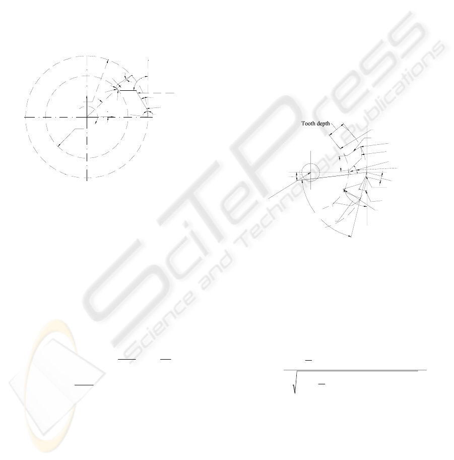
The composite curve in XY plane is composed of
vertices V
1
…V
7
(Figure 1). Let D, D
R
and l
1
be
cutter diameter, root circle diameter and width of
primary land respectively and α
i
, β
i
, γ
i
be the angles
of rotation of surface patch ‘i’ about X, Y, Z axis
respectively.
γ
V
γ
γ
V
V
V
V
V
V
V
D
D
2
3
1
γ
0
1
2
3
4
5
6
7
O
X
Y
ψ
R
c
1
Figure 1: Sectional Curve of a Slab Mill.
The cross-section curve V
1
V
7
is composed of five
parametric curve segments defined in terms of
parameter ‘s’. The curve segments p
1
(s), p
2
(s), p
3
(s)
and p
5
(s) are straight lines between vertices V
1
V
2
,
V
2
V
3
, V
3
V
4
and V
6
V
7
respectively, while the curve
p
4
(s) is a circular arc of radius R. The sweep
surfaces Σ
1
to Σ
5
are formed as p
i
(s, φ) = p
i
(s).T
s
.
For helical mill's tooth, if φ is the rotational angle
and P the pitch of the helical cutter, then the
transformation matrix T
s
is
⎥
⎥
⎥
⎥
⎥
⎦
⎤
⎢
⎢
⎢
⎢
⎢
⎣
⎡
−
−
=
0
2
00
0100
00cossin
00sincos
π
φ
φφ
φφ
P
S
T
;
P
L
P
L
π
φ
π
≤≤
−
(1)
The body of the slab mill has left end surface
(Σ
50
), right end surface (Σ
51
), bore surface (Σ
52
) and
the keyway. The body of slab mill has eight
transitional surfaces in the form of chamfers. The
chamfer between surface patch Σ
i
and Σ
j
is denoted
as σ
i,j
, where i = 50, 51 and j = 52, 53, 54, 55.
2.2 Mapping Relations for Slab Mills
The process of conversion of tool angles given in
one nomenclature to other is known as mapping.
When 3D rotational angles developed in this work
are converted to conventional 2D nomenclatures, the
mapping is called the forward mapping. On the
contrary, when angles defined as per existing
standards are mapped to proposed rotational angles,
the process is called the inverse mapping. The angles
for a slab mill are shown in Figure 2.
Radial Rake Angle (γ
R
) is formed by face Σ
1
with
ZX plane and viewed on projection to XY plane. To
find γ
R
, the normal to Σ
1
is projected on XY plane
and dot product of the projected normal with the unit
vector along Y axis is taken. This gives cosγ
R
=
cos(γ
1
+φ). For straight tooth cutter, angle φ is zero,
while for helical cutters, γ
R
is evaluated on z=0
plane. This gives γ
R
= γ
1
Tooth thickness
Tooth face
Cutting edge
Back of tooth
Flute
Land
Fillet (radius R)
Center of cutter
Lip angle
2nd clearance angle
Relief angle
1st clearance angle
Gash angle
Root circle
Radial rake angle
Figure 2: Conventional Tool Geometry of Slab Mill.
In the same fashion, relief angle (α
P
) is formed
by land Σ
2
about YZ plane when projected on XY
plane and is given as α
P
= γ
2
. Surface patch Σ
3
(Flank) of tooth forms first clearance angle (α
1P
)
with YZ plane on projection to the XY plane and the
angle α
1P
is expressed by the following relation:
()
()
⎥
⎥
⎥
⎥
⎥
⎦
⎤
⎢
⎢
⎢
⎢
⎢
⎣
⎡
−+
⎟
⎠
⎞
⎜
⎝
⎛
+−
−+
⎟
⎠
⎞
⎜
⎝
⎛
+−
=
−
2
213
2
213
213213
1
1
cossin
2
coscossinsin
2
cos
γγ
φγφγ
α
lVl
D
V
lVl
D
V
yx
yx
P
Second Clearance Angle (α
2P
) is formed by patch
Σ
4
and can be expressed as α
2P
= γ
4
. Gash angle (δ)
is the angle of fillet and is 908+γ
1
-γ
4
+(2π/N), where
N is the number of teeth of the slab mill. Lip angle is
the angle formed by the tooth solid side at the
cutting edge. In terms of rotational angles the lip
angle is evaluated as υ
la
= 908+γ
1
-γ
2
.
SURFACE MODELING OF MULTI-POINT, MULTI-FLUTE CUTTING TOOLS
173
3 MODELING OF END MILL
End mills are multi-point cutters with cutting edges
both on the end face and the circumference (Drodza,
1983). Figure 3 shows the projected geometry of a
flat end mill. The geometry of an end mill consists
of geometry of fluted shank and end geometry.
Figure 3: Two-Dimensional Geometry of End Mill.
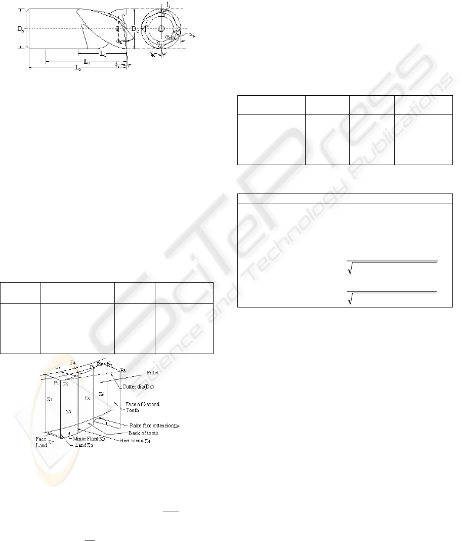
3.1 Geometry of Fluted Shank
A single tooth of the end mill is modeled with nine
surface patches, labeled Σ
1
to Σ
9
(Table 1). Surfaces
Σ
1
to Σ
6
are the surfaces on the fluted shank. These
surfaces are formed as helicoidal surfaces. The
composite sectional curve (P
1
…P
8
) is composed of
six segments (Figure 4). Three segments of the
composite curve are straight lines and correspond to
the three land widths, namely peripheral land, heel
and face. While the other three segments are circular
arcs of radii r
3
, r
2
and R and correspond to fillet,
back of tooth and blending surface.
Table 1: Surface Patches of End Mill.
Symbol Surface Patch
Name
Symbol Surface
Patch Name
Σ
1
Σ
2
Σ
3
Σ
4
Σ
5
Face
Peripheral Land
Heel
Blending Surface
Back of Tooth
Σ
6
Σ
7
Σ
8
Σ
9
Fillet
Face Land
Minor Flank
Rake Face
Extension
Figure 4: Modeling of an End Mill Tooth.
The helicoidal surface for fluted shank is described
as p(s,φ) = p(s).T
S
, where
In the above equation, L is the length of fluted
shank. The length may be equal to L
1
for flat end
mills and (L
1
-D
c/
/2) for ball end mills. Three
different sweeping rules can be formulated for the
fluted shank and the end profile of the cutter. These
rules are for cylindrical, conical and hemispherical
helical path.
3.2 Mapping Relations for End Mill
Mapping guide table (Table 2) shows the planes that
forms the conventional angles. The forward mapping
relations are summarized in Table 3.
Table 2: Mapping Guide Table for End Mill.
Conventional
Angles
Formed
by
About
the Plane
Plane of
Projection
γ
R
α
R
α
1R
φ
e
α
A
Σ
1
Σ
2
Σ
3
Σ
7
Σ
7
ZX
YZ
YZ
XY
XY
XY
XY
XY
ZX
YZ
Table 3: Forward Mapping Relations for End Mill.
Conventional Angles Rotational Angles
Radial Rake Angle, ±γ
R
=
1
γ
m
Radial Relief Angle, α
R
=
2
γ
Radial Clearance Angle, α
1R
=
3
γ
Axial Relief Angle, α
A
=
⎥
⎥
⎦
⎤
⎢
⎢
⎣
⎡
+
−
7
2
7
2
1
2
7
1
cossincos
cos
cos
ααγ
α
End Cutting Edge , φ
e
=
⎥
⎥
⎦
⎤
⎢
⎢
⎣
⎡
+
−
7
2
7
2
1
2
7
1
cossinsin
cos
cos
ααγ
α
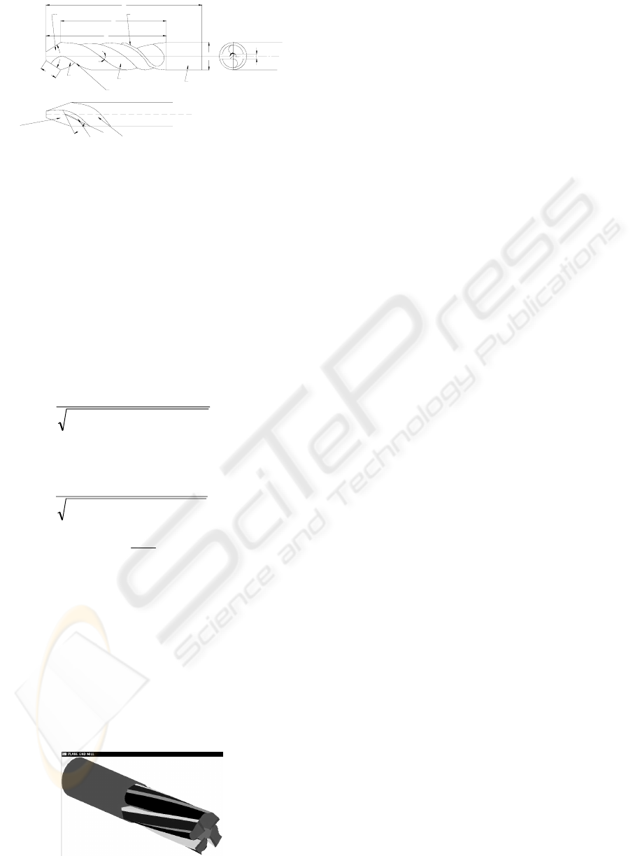
4 MODELING OF TWIST DRILL
Drills are rotary cutting tools used for the generation
of holes (Drodza, 1983). In this paper, modeling of a
two-flute, right-cut, straight shank type of solid twist
drill is presented. This is the most commonly used
drill for originating holes.
Geometrically a drill is made of (i) drill body and
(ii) shank. Drill body is the portion responsible for
material removal and the part by which drill is held
and driven in a drilling machine is shank. The drill
body may be segmented into (i) flute and (ii) end
geometry. The flute is the cutting portion of the drill.
The end of the drill is the portion that facilitates
entry of the drill into the workpiece. The
conventional two-dimensional projected geometry of
a twist drill is shown in Figure 5.
⎥
⎥
⎥
⎥
⎥
⎦
⎤
⎢
⎢
⎢
⎢
⎢
⎣
⎡
π
φ
φφ−
φφ
=
1
2
P
00
0100
00cossin
00sincos
s
T
for
P
L
π
φ
2
0 ≤≤
(2)
GRAPP 2007 - International Conference on Computer Graphics Theory and Applications
174
L
L
L
D
S
W
Land
Shank
Flute
Face
Body
2
β
Minor cutting edge
Major flank
λ
ψ
Flute
Land
Lip relief angle
α
4
2
1
Figure 5: 2D Projected Geometry of a Twist Drill.
The sectional geometry of the fluted shank has
three segments, out of which one is a straight line
and forms land (Σ
2
). The other two segments are
circular in geometry and on sweeping form flank
(Σ
3
) and face (Σ
1
) respectively. The drill end is made
of as many surface patches as the number of flutes.
For a two-flute drill, two surface patches form the
drill end. They are labeled as Σ
4
and Σ
5
and known
as lip relief surfaces. The lip relief surfaces can be
planar, cylindrical, conical and helicoidal. For a
drill, the forward mapping relations are:
Half Point Angle,
⎥
⎥
⎦
⎤
⎢
⎢
⎣
⎡
+
=
−
4
2
4
2
4
2
44
1
coscossin
cossin
cos
βγβ
γβ
β
(3)
Chisel Edge Angle, ψ = 90˚ - γ
4
. (4)
Relief Angle,
⎥
⎥
⎦
⎤
⎢
⎢
⎣
⎡
+
=
−
4
2
4
2
4
2
4
1
cossinsin
cos
cos
βγβ
β
α
(5)
Helix Angle,
⎟
⎟
⎠
⎞
⎜
⎜
⎝
⎛
=
−
c
D
P
π
λ
1
tan (6)
Peripheral Relief Angle, α
p
= γ
2
(7)
5 VALIDATION
This section presents an example on 3D modeling of
an end mill. The parameters used to construct the
model of end mill are referred in ANSI/ASME
B94.19-1985 standards. The resultant cutter is
rendered (Figure 6) in OGL environment.
Figure 6: Rendering of an End Mill.
6 CONLUSIONS
The present work has covered the 3D modeling of
the multi-point fluted cutters (slab mills, end mill
and drills) by mathematically expressing the
geometry of the cutting tools in terms of various
biparametric surface patches. Four rotational angles
(γ
1
, γ
2
, γ
3
, γ
4
) are used to define the geometry of a
slab mill along with other dimensional parameters.
Similarly, four rotational angles (γ
1
, γ
2
, γ
3
, α
7
) and
three rotational angles (γ
2
, β
4
, γ
4
) are defined to
model an end mill and drill respectively. The
mathematical definitions of the surfaces have been
used to obtain the standard 2D tool angles from
these proposed rotational angles. The inverse
relationships to obtain the rotational angles from the
conventional angles are also obtained. The entire
exercise attempts to recast the method of defining a
cutting tool in terms of 3D geometric models.
REFERENCES
Armarego, E.J.A., Kang; D.,1998. Computer-Aided
Modeling of the Fluting Process for Twist Drill
Design and Manufacture, Annals of the CIRP, Vol.47,
No.1, pp. 259-264.
Chen, C.-K., Lin, R.-Y., 2001. A Study of Manufacturing
Models for Ball-End Type Rotating Cutters with
Constant Pitch Helical Grooves, International Journal
of Advanced Manufacturing Technology, Vol.18,
No.3, pp. 157-167.
Drodza, T.J., Wick, C., 1983. Tool and Manufacturing
Engineers Handbook, Volume I - Machining, Society
of Manufacturing Engineers, Dearborn, MI.
Hsieh, J.F., Lin, P.D., 2002. Mathematical Model of
Multiflute Drill Point, International Journal of
Machine Tool & Manufacture, Vol.42, pp. 1181-1193.
Sheth, D.S., Malkin, S., 1990. CAD/CAM for Geometry
and Process Analysis of Helical Groove Machining,
Annals of the CIRP, Vol.39, No.1, pp. 129-132.
Tandon Puneet, Gupta P., Dhande S.G., 2004. Geometric
Modeling of Slab Mills, Proceeding of International
CAD conference - CAD'04, Thailand.
Tandon Puneet, Gupta P., Dhande S.G., 2005. Geometric
Modeling of End Mills, Computer Aided Design and
Applications, Vol. 2, Nos. 1-4, pp.57-66.
Wang, G.C., Fuh, K.H., Yan, B.H., 2001. A new
mathematical model for Multifacet Drills derived by
using Angle-Solid Model, International Journal of
Machine Tool & Manufacture, Vol. 41, pp. 103-132.
SURFACE MODELING OF MULTI-POINT, MULTI-FLUTE CUTTING TOOLS
175
