
INTERACTIVE COLLISION DETECTION
FOR FREE-VIEWPOINT VIDEO
Bert De Decker, Tom Mertens and Philippe Bekaert
Expertise Centre for Digital Media, Hasselt University, Wetenschapspark 2, Diepenbeek, Belgium
Keywords:
Video-based graphics, animation and rendering, collision detection, rigid body simulation, visual hull.
Abstract:
We present a novel way of interacting with a virtual 3D scene in the context of free-viewpoint video. Using a
multi-camera setup, our technique detects collisions between virtual objects and real objects, including people.
We perform collision computations directly on the image data, as opposed to reconstructing the full geometry
of the subject. This reduces implementation complexity, and moreover, yields interactive performance. We
demonstrate the effectiveness of our technique by incorporating it in a rigid body sim ulation. The subject
can interact with virtual objects and observe his or her actions while being able to adjust the viewpoint, all in
real-time.
1 INTRODUCTION
A lot of work has been invested in reconstructing 3D
shapes from still or moving images in the last decades
in the field of Computer Vision, and recently also in
Computer Graphics. In this context, free-viewpoint
video has emerged as a extension of traditional live-
action video, which enables a more immersive expe-
rience for the observer. In particular, the observer is
able to view the scene from any viewpoint as opposed
to a single viewpoint. Scenes one typically considers
involve some sort of human performance, possibly in-
cluding other moving elements. To implement such a
system, a multi-camera setup is used to reconstruct
shapes and material properties of the scene, which
can then be used to render novel views. This pro-
cess typically consists of three steps: capturing the
scene and/or performance, analysis of video frames
and synthesis of novel viewpoints. Analysis and syn-
thesis might be performed offline, or offline and on-
line, respectively. Alternatively, the entire process
might be implemented as a real-time system such that
live performances can be viewed in real-time, akin to
a live television broadcast. Since we are dealing with
interaction (usually involving a human subject), our
work is mostly applicable to the latter application do-
main.
In this paper, we go beyond free viewpoint video
by adding interactions between the real world and a
virtual scene. More precisely, we introduce a tech-
nique to determine collisions between real and vir-
tual objects. A straightforward approach to tackle this
problem, would be to apply 3D reconstruction tech-
nique “X” to obtain a triangle mesh of the scene, on
which standard collision detection schemes can be ap-
plied. However, it would be better to avoid this inter-
mediate reconstruction step, for the sake of simplicity
and computational efficiency. Our technique is there-
fore designed to work directly on the information in
the video frames.
In the classic collision detection problem, contact
is determined from a full 3D description of the partic-
ipating shapes (i.e. a triangle mesh). In our case, each
camera only provides a discrete, 2D description of the
real-world shapes. First of all, the information of the
set of 2D frames acquired from each camera has to be
aggregated to derive a collision test in 3 dimensions.
We implement this based on the concept of a visual
hull, i.e. the volume extruded from the silhouette of
an object or subject. This information is readily avail-
able as a result of fast and simple foreground segmen-
tation, and thereby avoids a costly 3D reconstruction
step. Since camera registration is inherently a discrete
process (granularity = one pixel), we have to be care-
114
De Decker B., Mertens T. and Bekaert P. (2007).
INTERACTIVE COLLISION DETECTION FOR FREE-VIEWPOINT VIDEO.
In Proceedings of the Second International Conference on Computer Graphics Theory and Applications - AS/IE, pages 114-120
DOI: 10.5220/0002078901140120
Copyright
c
SciTePress
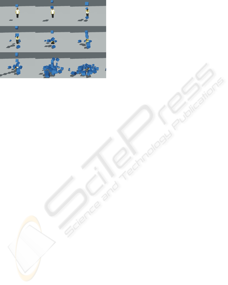
Figure 1: A person, captured by multiple calibrated digi-
tal video cameras, interacts with a rigid body simulation at
interactive speeds.
ful in avoiding aliasing artifacts when determining the
exact collision location. Finally, the analysis has to
process data at a high bandwidth, since frames from
multiple cameras have to be processed at each instant,
while maintaining interactive performance. We there-
fore introduce a simple acceleration scheme to effi-
ciently test the visual hull data. These issues will be
explored in the remainder of the paper. We conclude
with results and directions for future work.
2 RELATED WORK
Free Viewpoint Video Our collision detection
technique was developed specifically with free view-
point video in mind. Since our technique is fairly sim-
ple, and works directly on the video frame data, we
are free to choose any existing free viewpoint video
reconstruction and rendering technique, such as the
voxel-based visual hull calculation by Hasenfratz et
al. (Hasenfratz et al., 2003) or the real-time polygo-
nal visual hull calculation by Matusik et al. (Matusik
et al., 2001). For our experiments, we implemented
the photohull calculation technique by Li et al. (Li
et al., 2004).
Collision Detection between Virtual Objects
Many techniques have been developed for collision
detection between only virtual objects (Guendel-
man et al., 2003; Baraff, 1992; Pauly et al., 2004;
Heidelberger et al., 2004) , cloth (Bridson et al.,
2002; Govindaraju et al., 2005) , deformable objects
(Debunne et al., 2001; Teschner et al., 2005; Dewaele
and Cani, 2004) , articulated objects (Redon et al.,
2004) and fluids (Losasso et al., 2006) .
Interaction Techniques The technique presented
here can also be seen as a way to interact with a vir-
tual environment (Hand, 1997; Bowman and Hodges,
1997; Grossman et al., 2004). Yoshifumi et al. (Ki-
tamura et al., 2003) implement interaction between
real and virtual objects by defining a constrained set
of physical laws. Xiyong et al. (Wang et al., 2005)
present a system where users can manipulate scanned,
articulated virtual representations of real objects.
Force Feedback In our work, we perform a one
way interaction: the real world can interact with the
virtual world, but not vice versa. There are also some
techniques that provide interaction in 2 directions. An
example of such a technique is presented by Linde-
man et al. (Lindeman et al., 2004). They describe a
system that gives haptic feedback to a user that walks
around in a virtual environment. Since we allow arbi-
trary real-world objects in our scene, it is not readily
possible to implement such feedback.
Collision Detection between Real and Virtual Ob-
jects Allard et al. (Allard and Raffin, 2006; Allard
et al., 2006) present a physically-based animation sys-
tem in which users can interact with the objects in
the scene using a visual hull. They calculate a mesh
representation of the visual hull of the real world
and use this mesh to calculate the collision detection
and response information. Breen et al. (Breen et al.,
1996) and Hasenfratz et al. (Hasenfratz et al., 2004)
also describe a system where some geometry of the
real world is calculated as a preprocessing step in the
collision detection between real and virtual objects.
Stam (Stam, 2000) presents a method where a depth
map is calculated by filming a person with a special
camera, using this depth map a person can interact
with a fluid simulation.
We bypass the mesh generation and work directly
on the images which results in higher performance.
Most related to our work is the system by Lok et
al. (Lok et al., 2003). Instead of using an interme-
diate mesh representation of the real world, they ras-
terize every virtual triangle to all the input cameras to
determine collisions using graphics hardware. How-
ever, they assume there is at most one collision be-
tween one virtual object and the visual hull of the real
object at a time. This is true in some cases (for ex-
ample a virtual ball bouncing off a wall). However,
when a virtual box lies on a real table, for instance,
this assumption breaks down. The main advantage of
our algorithm over theirs, is the fact that we take into
account multiple simultaneous collisions.
INTERACTIVE COLLISION DETECTION FOR FREE-VIEWPOINT VIDEO
115
3 OVERVIEW
The main contribution of this paper is an algorithm to
detect and respond to collisions between real and vir-
tual objects. Collisions are determined from captured
video data of real scene with multiple digital cameras.
The collision algorithm is based on the visual hull
representation (Laurentini, 1994). When a virtual ob-
ject intersects the visual hull of the real scene at a
given time, the system will resolve this collision by
moving the virtual object out of the visual hull and by
flipping its velocity vector over the tangent plane of
the visual hull at the collision point. This way, the vir-
tual object is no longer intersecting the visual hull and
is moving away from it after the collision. An impor-
tant difference between traditional collision detection
and this case, is that the shape of the real objects is
only available at discrete time steps. So it is impossi-
ble to find to exact moment of contact. Instead of pre-
venting collisions, the system will recover from them
by computing an appropriate collision response vec-
tor that undoes the penetration, as introduced by Lok
et al. (Lok et al., 2003). The distance the virtual object
is moved to undo the penetration should be as small
as possible, so the collision response vector is chosen
to be perpendicular to the penetrated real-world ob-
ject and its length is chosen to be such that the virtual
object will no longer be in a state of collision in the
next time step. Other definitions of the collision re-
sponse vector could be used, but we found that this
one gives good results while still allowing interactive
speeds. For example a better collision response vector
could be constructed by taking the speeds of the col-
liding objects into account. But since it is very hard
to calculate the speed of the surface of the visual hull
of the real object at interactive speeds, we can not use
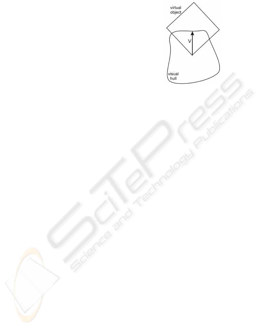
it for our purpose. In figure 2 a simple example is
shown that illustrates the technique.
4 POINT COLLISION
DETECTION
Before detailing our general collision detection
scheme, we first focus on the special case of deter-
mining collision between a real object and a point. In
the following section, this procedure will be general-
ized to arbitrary objects.
4.1 Inside/Outside Test
For every input camera, we compute the object’s sil-
houette using simple background subtraction (Cheung
et al., 2000), which forms the visual hull. Since we
Figure 2: A simple example where a virtual object is inter-
secting the visual hull. The collision response vector is rep-
resented by v, the vector that is perpendicular to the visual
hull. If the virtual object is translated along v, the virtual
object is no longer intersecting the visual hull.
know the intrinsic and extrinsic parameters of each
camera, each point can be projected into its view. By
simply looking up the foreground/background classi-
fication and the corresponding pixel, we can deter-
mine whether the point is inside the hull.
Even though this test is extremely simple, when
many such queries are executed, computational per-
formance becomes limited by the sheer amount of
memory access. Bounding volumes of the visual
hull can be used to reduce the number of times an
explicit image-based inside/outside test needs to be
performed. We use 2 types of bounding volumes:
the bounding frustum of the visual hull, and the axis
aligned bounding box of this frustum. The bounding
frustum is constructed from the center of projection of
the corresponding camera and the 2D bounding rect-
angle of the actual visual hull. This rectangle can be
obtained efficiently in a single pass by iterating over
all visual hull pixels and keeping track of the extreme
coordinate values. Before testing a point against the
4 planes that form the frustum, we first test it against
the axis-aligned bounding box of the bounding frus-
tum, as this test is even simpler.
4.2 Collision Response
If a point lies inside the visual hull, the collision re-
sponse vector has to be calculated. Figure 3 shows
an example where the collision response for point a is
needed.
As described in section 3, the collision response
vector has to be perpendicular to the visual hull sur-
face and when the rigid body is translated along this
vector, it is no longer intersecting the visual hull.
GRAPP 2007 - International Conference on Computer Graphics Theory and Applications
116

Figure 3: Left: one of the silhouette images. Right: a 5x5
window of this silhouette image, point a is intersecting the
visual hull, point b is the closest point on the surface, but
with the wrong normal, c is the point on the surface with
the right normal
The naive way to find this vector would be to find
the point on the visual hull surface that is the closest to
a (point b in the figure) and defining the collision re-
sponse vector as the vector connecting a and b (vector
v is the figure). To find the point b, a is projected to all
the input images. For every iteration of the search al-
gorithm, a square window around the projection of a
is considered for every input image. If one of the pix-
els of the window is not inside the silhouette image,
than the projection of b is found. To obtain b we sim-
ply need to backproject its projection into 3D space.
The initial size of the window is 3 by 3 pixels and it
grows at every step of the iteration until we find the
projection of b. But one pixel distance in one cam-
era image corresponds to a different distance in 3D
than one pixel distance in another camera image. The
search window of cameras that are almost perpendic-
ular to the surface grows faster than that of cameras
that are at an angle with respect to the surface. The
grow speed of the windows is calculated as follows:
for every camera the pixel below and the pixel on the
right of the pixel where b was projected are projected
back in 3D and the smallest distance between b and
these backprojected pixels is called d. So each cam-
era has its own d and the maximum of these values
is called dmax. The growspeed for the window of a
camera is now defined as dmax / d.
When point a lies far away from the surface of the
visual hull, the algorithm for the calculation of the
collision response described above would be a good
option and the direction of v would be close to the
surface normal. But due to the discrete nature of the
input images, this presents a problem for points close
to the surface of the visual hull. If a was for exam-
ple a boundary pixel, the length of v would be half
a pixel and there would only be 8 possible directions
for v: up, down, left, right, front and back. [When
using v to calculate the normals of the visual hull, the
visual hull surface will not be smooth, instead there
would be a sharp edge at points in space that are pro-
jected onto the edge of two neightbouring pixels that
are part of the silhouette boundary of one of the in-
put images.] We don’t want the normal at one point
of the surface of the visual hull because it is prone to
the discrete nature of the images, instead we want the
normal of some area around the point, integrating out
the discrete nature of the images.
To construct a collision response vector with the
same direction as this better surface normal, the fol-
lowing algorithm is used. The point b is calculated
as described above. Typically, there is only one input
image for which the projection of b lies on the silhou-
ette boundary, for all the other images it will lie inside
the silhouette. So only one input image provides in-
formation about the surface normal at b. The excep-
tion to this is when b lies on an edge or on a corner
of the visual hull, in that case the projection of b lies
on the silhouette boundary of multiple images. When
this special case occurs, the first image for which the
projection of b lies on the silhouette boundary is cho-
sen, the others are ignored and the algorithm acts as
if the special case does not exist. So when the spe-
cial case occurs, the algorithm doesn’t return the nor-
mal at b, but the normal of another point that lies at
the distance of one pixel from b. While this is not
completely correct, this will not be visible in the final
simulation and is a lot faster to calculate. So only one
image is needed to calculate the 3D surface normal
of the visual hull at point b. A 2D silhouette normal
is calculated at the projection of b in this image. For
every pixel that is outside the silhouette and inside a
5x5 window around the projection of b, a 2D vector is
created from the projection of b to this pixel. The 2D
silhouette normal is the average of all these vectors.
The 3D normal vector is obtained by backprojecting
the 2D silhouette normal to 3D space. The final col-
lision response vector w is defined as the vector con-
necting the collision point a and point c where c is the
intersection between the visual hull surface and the
ray starting in a in the direction of the previously cal-
culated surface normal. The algorithm used to find c
is similar to the one used to calculate b, except that in
this case no search window is used but a search line
that grows longer and longer each iteration.
5 GENERAL COLLISION
DETECTION
To perform general collision detections with objects
instead of points, we represent each object as a col-
INTERACTIVE COLLISION DETECTION FOR FREE-VIEWPOINT VIDEO
117
lection of points using surface sampling. For each in-
dividual point of an object, we perform the collision
test and response computation as described in the pre-
vious section. We compute a single vector V by aver-
aging over all of the per-point response vectors of the
object. For each sampled point, we search along this
direction until a point on the hull boundary is found
and a vector connecting this point and the sampled
point is constructed. The response vector of the rigid
body is obtained by taking the longest of these vec-
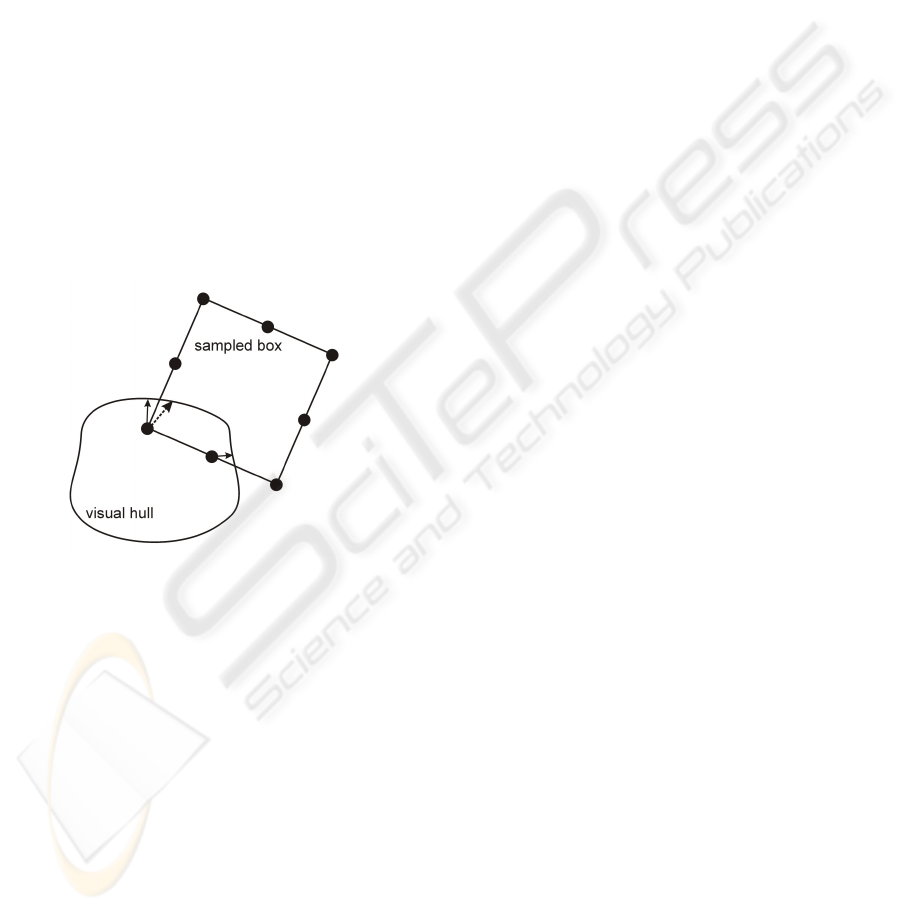
tors. See figure 4 for an illustration.
The difference with the technique by Lok et. al.
(Lok et al., 2003) is, they only consider one point of
the surface of the virtual object during the calculation
of the collision response. This is the reason why they
can not model certain effects, for example a virtual
box lying in rest on top of a real one. The technique
presented here does not have this limitation because
multiple points on the surface of the virtual object that
are in collision with the visual hull are taken into ac-
count.
Figure 4: Point-based collision detection for arbitrary ob-
jects. For each point, we compute a collision response vec-
tor. By rescaling the average of these vectors, the response
vector of the rigid body is obtained.
Bounding box tests can be used to cull entire ob-
jects for collisions tests: if the axis aligned bound-
ing box of the visual hull does not intersect with axis
aligned bounding box of the rigid body then the rigid
body will not intersect with the visual hull either and
further tests are not necessary.
If the virtual object is sampled too sparsely, it is
possible that the detection “misses” some collisions.
Because calculating the per-point test is very cheap,
it is possible to sample the objects dense enough
while still being able to perform the collision de-
tection at high speeds. In our implementation the
amount of samples used for a certain object depends
on the size of the object. In the experiment shown
in figure 1 between 250 and 500 samples per box are
used. Another advantage is that all objects that can
be point sampled can be dealt with, such as spheres,
meshes and implicit surfaces. The only requirement
on the pointsampling is that two neighbouring sam-
ples should lie close enough to each other in order that
no part of the visual hull could pass between them.
Uniform sampling will give the best accuracy for a
given number of samples, but is no requirement.
6 RESULTS
6.1 Collision Detection System
The algorithm described above was implemented in
a real-time free viewpoint video system. The cam-
era setup consists of 7 cameras positioned in a hemi-
sphere, and all the cameras are directed to the sub-
ject. The room is covered with green cloth to simplify
the background subtraction. The cameras are cali-
brated using Svoboda’s (Svoboda et al., 2002) calibra-
tion tool. The cameras are distributed across 3 PCs.
These PCs are responsible for acquiring the images
from the cameras and for calculating the silhouette
images. The images along with the silhouette images
are gathered on a central PC which performs the rigid
body simulation, the collision detection and the vi-
sualization. The real-world scene is rendered by the
Photohull plane sweeping algorithm by Li et al.(Li
et al., 2004) and runs entirely on the GPU. We cou-
pled our collision detection system with a rigid body
simulator (Open Dynamics Engine(ODE, 2006)).
Our proof-of-concept implementation runs at ap-
proximately 10 frames per second when 7 cameras
are used and the scene is rendered at a resolution of
640x480. The system can calculate collision detec-
tion response information at about 500K points per
second. The bottleneck is not the central PC which
does the visualization and collision detection, but the
transmition of the images over the network. For the
moment the images are not compressed when they are
sent over the network, taking more time than strictly
necessary. Simple run-length encoding of the visual
hull images will likely improve performance signifi-
cantly.
6.2 Experiments
In Figure 1, 5 and 6 we show some examples.
In our first experiment, shown in Figure 5, a stack
of virtual boxes on top of a real box is tipped over by
lifting the real box. This demonstrates how our tech-
nique is capable of modeling virtual objects that are
lying in rest on top of real ones, because we can deal
GRAPP 2007 - International Conference on Computer Graphics Theory and Applications
118
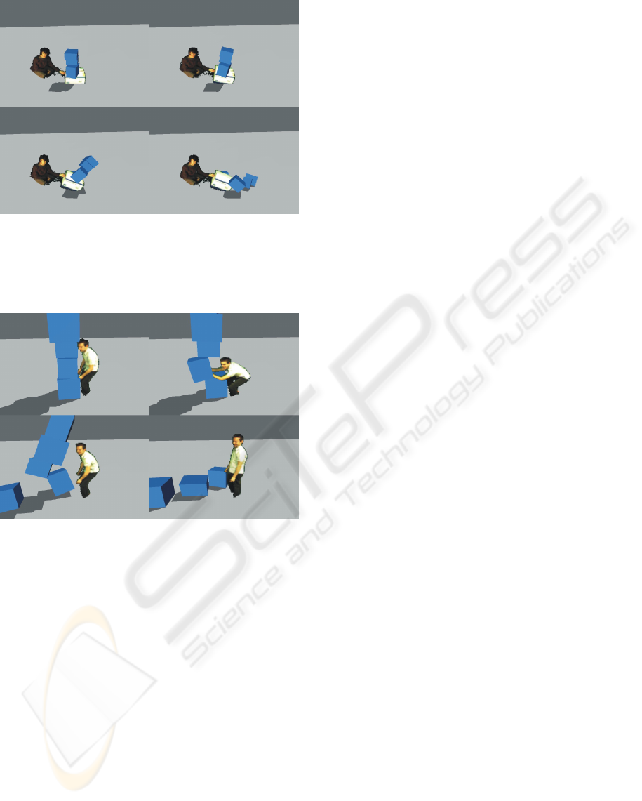
Figure 5: A stack of virtual boxes on top of a real box is
tipped over by lifting the real box. This demonstrates how
our technique is capable of modeling virtual objects that are
lying in rest on top of real ones, due to correct treatment of
multiple simultaneous collisions.
Figure 6: A real person topples a stack of virtual boxes.
with multiple simultaneous collisions. Figure 6 shows
the interaction between a human and a pile of boxes.
In the last experiment (Figure 1) we demonstrate a
scene involving many virtual objects.
7 CONCLUSION AND FUTURE
WORK
We presented a novel technique that interactively han-
dles collision detection between real and virtual ob-
jects in the context of a free-viewpoint video setup.
Using the concept of the visual hull extracted from
a number of different views of the real-world scene,
collisions are determined by point sampling the vir-
tual objects, and performing simple and efficient in-
side/outside tests on these points. Our technique is
fast enough for interactive applications, and com-
pared to previous visual hull-based approaches, we
are able to handle multiple simultaneous collisions.
At the moment, the system can not handle very
fast moving objects. If at one instant, the visual hull
is in front of a rigid body and at the next frame it is be-
hind the rigid body, the contact that should have been
detected is missed. To solve this, we need to know for
every camera which pixels were occupied by the real
object between the two time steps. We should also be
able to query the visual hull in between two frames,
so we can calculate the precise time of the collision
of 2 fast moving objects. When objects are moving
relatively slow as in our examples, we don’t need this
much precision to generate a plausible simulation.
The system could also be extended to make it pos-
sible for the users to grab virtual objects and move
them around in the real world. One could for example
have the user carry a button in his hand and when it
is pushed, the visual hull would becomes sticky and
objects touched by the user would stick to his body
until he releases the button.
The algorithm is also very suited for parallel im-
plementation on a cluster. Since we need multiple
machines to connect the cameras anyway, we might
as well use them to help in the collision calculations.
The main advantage would not be the increased frame
rate, but the possibility to use high resolution images.
The speed of the algorithm presented here is inde-
pendent of the resolution of the input images (except
for the background subtraction), but it requires that
all the images are gathered on one central machine
which implies bandwidth limitations. When using a
distributed approach, none of the images need to be
send over the network, and all the calculations regard-
ing one image are performed locally on the PC that
gathered the image from the camera.
ACKNOWLEDGEMENTS
The authors acknowledge financial support on a struc-
tural basis from the European fund for regional devel-
opment (ERDF), the Flemish institute for broadband
communication (IBBT), as well as impuls financing
from the transnationale Universiteit Limburg.
REFERENCES
Allard, J., Franco, J., Menier, C., Boyer, E., and Raffin, B.
(2006). The grimage platform: A mixed reality envi-
ronment for interactions. In ICVS.
Allard, J. and Raffin, B. (2006). Distributed physical based
INTERACTIVE COLLISION DETECTION FOR FREE-VIEWPOINT VIDEO
119

simulations for large vr applications. In IEEE Virtual
Reality Conference.
Baraff, D. (1992). Dynamic simulation of non-penetrating
rigid body simulation. PhD thesis.
Bowman, D. and Hodges, L. (1997). Techniques for grab-
bing and manipulating remote objects in immersive
virtual environments. In ACM Symposium on Inter-
active 3-D Graphics.
Breen, D., Whitaker, R., and Tuceryan, M. (1996). Inter-
active occlusion and automatic object placement for
augmented reality. In Computer Graphics Forum,
Blackwell Publishers.
Bridson, R., Fedkiw, R., , and Anderson, J. (2002). Robust
treatment of collisions, contact and friction for cloth
animation. In conference on Computer graphics and
interactive techniques.
Cheung, K. M., Kanade, T., Bouguet, J.-Y., and Holler, M.
(2000). A real time system for robust 3d voxel re-
construction of human motions. In Proceedings of the
2000 IEEE Conference on Computer Vision and Pat-
tern Recognition (CVPR ’00), volume 2, pages 714 –
720.
Debunne, G., Desbrun, M., Cani, M.-P., and Barr, A. H.
(2001). Dynamic realtime deformations using space
and time adaptive sampling. In ACM SIGGRAPH.
Dewaele, G. and Cani, M.-P. (2004). Interactive global and
local deformations for virtual clay. In Graphical Mod-
els.
Govindaraju, N., Knott, D., Jain, N., Kabul, I., Tamstorf,
R., Gayle, R., Lin, M., and Manocha, D. (2005). Inter-
active collision detection between deformable models
using chromatic decomposition. In ACM SIGGRAPH.
Grossman, T., Wigdor, D., and Balakrishnan, R. (2004).
Multi-finger gestural interaction with 3d volumetric
displays. In UIST ’04: Proceedings of the 17th an-
nual ACM symposium on User interface software and
technology, pages 61–70, New York, NY, USA. ACM
Press.
Guendelman, E., Bridson, R., , and Fedkiw, R. (2003).
Nonconvex rigid bodies with stacking. In ACM SIG-
GRAPH.
Hand, C. (1997). A survey of 3-d interaction techniques. In
Computer Graphics Forum, Blackwell Publishers.
Hasenfratz, J., Lapierre, M., Gascuel, J., and Boyer, E.
(2003). Real-time capture, reconstruction and inser-
tion into virtual world of human actors. In Vision,
Video and Graphics Conference.
Hasenfratz, J., Lapierre, M., and Sillion, F. (2004). A
real-time system for full body interaction with virtual
worlds. In Eurographics Symposium on Virtual Envi-
ronments.
Heidelberger, B., Teschner, M., and Gross, M. (2004). De-
tection of collisions and self-collisions using image-
space techniques. In WSCG.
Kitamura, Y., Ogata, S., and Kishino, F. (2003). A manip-
ulation environment of virtual and real objects using
a magnetic metaphor. In ACM Symposium on Virtual
Reality Software and Technology.
Laurentini, A. (1994). The visual hull concept for silhouette
based image understanding. In IEEE PAMI.
Li, M., Magnor, M., and Seidel, H. (2004). Hardware-
accelerated rendering of photo hulls. In Computer
Graphics Forum.
Lindeman, R. W., Page, R., Yanagida, Y., and Sibert, J. L.
(2004). Towards full-body haptic feedback: The de-
sign and deployment of a spatialized vibrotactile feed-
back system. In ACM Virtual Reality Software and
Technology (VRST).
Lok, B., Naik, S., Whitton, M., and Jr, F. B. (2003). Incor-
porating dynamic real objects into immersive virtual
environments. In Proceedings of the 2003 symposium
on Interactive 3D graphics.
Losasso, F., Shinar, T., Selle, A., and Fedkiw, R. (2006).
Multiple interacting liquids. In ACM SIGGRAPH.
Matusik, W., Buehler, C., and McMillan, L. (2001). Poly-
hedral visual hulls for real-time rendering. In Euro-
graphics Workshop on Rendering.
ODE (2006). Open dynamics engine (ode).
Pauly, M., Pai, D. K., and Guibas, L. J. (2004). Quasi-rigid
objects in contact. In Eurographics/ACM SIGGRAPH
Symposium on Computer Animation.
Redon, S., Kim, Y. J., Lin, M. C., and Manocha, D.
(2004). Fast continuous collision detection for articu-
lated models. In ACM Symposium on Solid Modeling
and Applications.
Stam, J. (2000). Interacting with smoke and fire in real time.
In Communications of the ACM.
Svoboda, T., Hug, H., and Gool, L. V. (2002). Viroom
- low cost synchronised multicamera system and its
self-calibration. In Gool, L. V., editor, Pattern Recog-
nition, 24th DAGM Symposium, LNCS, pages 512–
522. Springer.
Teschner, M., Kimmerle, S., Heidelberger, B., Zachmann,
G., Raghupathi, L., A. Fuhrmann, M.-P. C., Faure, F.,
Magnenat-Thalmann, N., Strasser, W., and Volino, P.
(2005). Collision detection for deformable objects. In
Computer Graphics Forum.
Wang, X., Kotranza, A., Quarles, J., Lok, B., and Allen,
B. D. (2005). Rapidly incorporating real objects for
evaluation of engineering designs in a mixed reality
environment. In 3D User Interfaces Workshop, IEEE
Virtual Reality.
GRAPP 2007 - International Conference on Computer Graphics Theory and Applications
120
