A VIRTUAL ENVIRONMENT FOR ARCHIVING
MICRO-PRESENCE WITH IMAGE-BASED MODEL ACQUISITION
Masahiko Morita
1
, Tastuya Saito
2
and Kenji Kohiyama
1
1
Graduate School of Media and Governance, Keio University, 5322 Endoh, Fujisawa-shi, Kanagawa, Japan
2
Tokyo National University of Fine-Arts and Music, 12-8 Ueno Kouen, Taito-ku, Tokyo, Japan
Keywords:
Computer graphics, photography, transparent, transparency, diffusivity.
Abstract:
Micro Archiving is a new method of photography that helps anybody digitally archive minute structures that
existing capturing systems cannot deal with. For research use, it is an effective way to make high-fidelity
virtual specimens of small objects that allowscholarstosharethepreciousacademicresourcesover the Internet
in a digital format. For commercial use, the virtual models captured by the technology can be applied to
computer graphics, games, digital cinemas and other digital entertainment media. Technically, our Micro
Archiving technology enables easy and fast construction of high-quality and high-resolution textured virtual
3D models of small objects. Currently, application contents of Virtual Reality, Augmented Reality and other
interactive media are dependent on the use of elaborate 3D models, which require expensive manual task.
Micro Archiving technology provides automatic capturing process that can comprehensively handle a high-
resolution all-focused imaging, 3-dimensional modeling and transparency capturing simultaneously. Micro
Archiving is best suited for minute and complex objects such as machine parts, insects, plants and small
archaeological materials.
1 INTRODUCTION
Invention of optical devices such as telescopes and
microscopes widened the perceivable spectrum of the
reality of the natural world by allowing us to see what
is invisible to our naked eyes.
Macro
Micro
Hidden
Visible Reality
Micro-Presence
Reality
Hidden
Reality
Figure 1: Micro Presence.
As well as revealing hidden aspect of the world,
archiving it has been a challenge of importance in
research fields where replicable duplication of spec-
imens and samples plays a crucial role. For example,
in biological studies on a small animals such as in-
sects and microscopic organisms, a photography and
hand-drawn sketches help researchers share scientific
knowledge on invariable specimens. This applies to
studies on artificial objects such as archaeological ma-
terials from the ancient time. In ancient sculptures
and fossils, their fine surface structures are historical
and cultural proofs that tell about how the objects are
produced and how they are used. Archiving and in-
vestigating these proofs is an important element of a
research task.
Here, the concept of Micro-Presence is introduced
to mean a kind of reality that is too small to be directly
experienced by our sensorial organs. A microscope is
a good example of a device to unveil Micro-Presence
by providing us with a way to observe microstructures
of both natural and artificial objects.
Archiving Micro-Presence such as insects, plants,
mineral substances and small-sized archaeological
findings for research use is often useful in that it al-
lows researchers and archaeologists to observe elabo-
rate virtual samples to inspect physical features with-
out having the actual samples. Use of virtual sam-
ples became a major technical topic as multimedia
database technology has highly advanced in the last
decade and the access to it has became extremely low-
cost. This trend will be accelerated in the future as
145
Morita M., Saito T. and Kohiyama K. (2007).
A VIRTUAL ENVIRONMENT FOR ARCHIVING MICRO-PRESENCE WITH IMAGE-BASED MODEL ACQUISITION.
In Proceedings of the Second International Conference on Computer Graphics Theory and Applications - GM/R, pages 145-152
DOI: 10.5220/0002081101450152
Copyright
c
SciTePress

the bandwidth of the Internet increases and interface
technology becomes easily accessible. Our project,
Micro Archiving, aims at developing a technology to
archive Micro-Presence in highquality. For research
use, it is an effective way to make highfidelity vir-
tual specimens that allow scholars to share academic
resources over the Internet. For commercial use, the
virtual models captured by our technology can be ap-
plied to computer graphics, games, digital cinemas
and other entertainment media. The technical goal
of this project was to build a new device for archiv-
ing small physical objects in digital form on these ad-
vancing future platform for helping researchers con-
duct research. The proposed imaging device needed
to have specific features for this use and we designed
the system to satisfy this goal. Our technique can scan
3-dimensional structure, all-focused color image, dif-
fusion and transmission coefficients of a target object.
A small object often has very fine and minute
structures that require a sophisticated optical device
such as a microscope to be observed. For generating
an all-focused image, where all the picture elements
are focused, a con-focal microscope is one effective
choice to scan a target object in high-resolution and
high quality. However, it has a deficiency in that it
cannot capture color information. Traditionally, for
creating archives of small physical objects from ar-
chaeological sites,microscopic cameras and other 2-
dimensional optical apparatus have been used. This
kind of an image resource is a historical asset that
provides cultural and scientific explanation on what
our ancestors’ life and technologies of those days
were like. These replicable resources are one of the
most important elements in conducting an archaeo-
logical research. However, the imaging technique
is accompanied by loss of information that derives
from transformation of 3-dimensional structure to the
2-dimensional medium. To solve this problem, 3-
dimensional scanning technologies have been attract-
ing attention in the research field. A 3-dimensional
scanner is a device that can capture 3-dimensional
structure of the target object often with color infor-
mation.
There are varieties of 3-dimensional scanners for
different uses. lazer-scanning technique is probably
the most popular technique and there are a number of
commercial products based on this technique. There
is another technique that utilizes an active lighting.
By projecting a certain pattern on a target object and
recognizing the projected pattern, this technique an-
alyzes the 3-dimensional surface shape of the target
object. In these two methods, color-information are
captured in a separate process often with a differ-
ent imaging device. In Stereo camera method, cor-
responding two points in two images taken by a set
of camera arranged in parallel are extracted to recon-
struct 3-dimensional surface structure of a target ob-
ject. This method is effective in scanning a large-scale
object such as an architectural structure and a land-
scape(Levoy, 2000). However, they have deficiency
in that they cannot deal with an extremely small ob-
ject less than 5 cm.
2 SYSTEM DESIGN
Our Micro Archiving technology can comprehen-
sively handle high-resolution all-focused imaging, 3-
dimensional capturing and transparency capturing si-
multaneously. Constructing high-resolution 3D mod-
els is an expensive and time-consuming task. In often
cases, 3-dimensional scanners and other image-based
modeling methods are used to automate this process.
However, existing systems had a trouble in case of a
small object. This is the main issue that our newly
proposed method solves. As we design the system,
we examined required features and functions that sat-
isfy our goal of providing researchers with an ultimate
archiving system.
2.1 Depth Measurement
It was the primal objective that our system can cap-
ture 3-dimensional structure of a small object that ex-
isting technique cannot deal with. Small objects, es-
pecially in case of a natural object and small animals
such as mineral materials and insects, have complex
and minute structures of fine concavity and convexity.
Our system needed to capture these physical
features. Our methodology is based on an exist-
ing image-based model acquisition method called
”Shape-from-focus”(Nayer and Nakagawa, 1994). In
general, Shape-from-focus method is done in the fol-
lowing process. Firstly, a optical device, usually a
camera, is focused onto a part of the target object. By
slightly changing the focal length of the optical de-
vice, a sequence of images are taken each of these
images contains different region in focus as shown in
figure 2. In general, focusing depends on the distance
from the camera to the target object. Therefore, by
extracting focused pixels in each image, it is possi-
ble to measure the 3-dimensional surface shape of the
target object.
However, the drawback of this method is that it is
difficult to generalize the focus model. Especially in
case of a complex object, pixels that are out of focus
affect neighboring pixels and this effect is extremely
complex to analyze. In general, a pixel becomes the
GRAPP 2007 - International Conference on Computer Graphics Theory and Applications
146
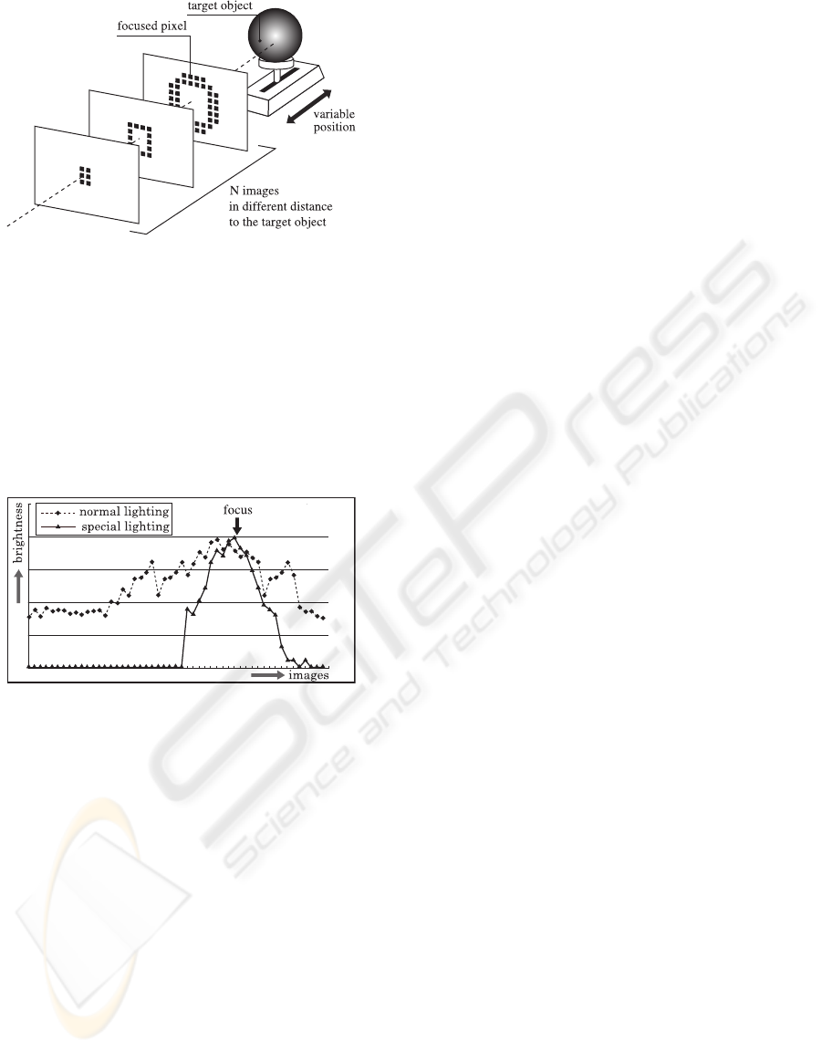
Figure 2: Shape from Focus.
brightest when it is in focus. The figure shows transi-
tion of brightness of a pixel in the captured sequence
of images. The x-axis represents the distance from the
camera to a part on the target object corresponding to
the pixel. As can be seen, it is difficult to know at what
position the pixel is focused(Figure 3 : normal light-
ing). This is largely because of complicated blur ef-
fect of neighboring pixels. This effect becomes more
complex when measuring the 3-dimensional structure
of a very complex object.
Figure 3: Transition of Brightness under our slit-lighting
equipment... or a normal lighting equipment.
To simplify this complex blur effect, we designed
a special slit lighting system as shown in figure 4. The
lighting system and a digital camera is set up on a
shock prevention table. The slit lighting system is
composed of 8 illuminators which are attached to a
ring plate with a hole in the middle. A target object
goes through this hole when it is scanned. Each of the
illuminator is connected to a light-box through an op-
tical fiber cable. Light comes from the light-box and
gathered and bundled to about 0.5 mm thick by a lens
in the illuminator (Figure 5).
The slit-lighting system is arranged so that the
beam of light goes parallel with the focal surface of
the camera lens and it illuminates only the part of
the target object that is located very near to the fo-
cused part. Therefore, a sequence of captured images
contains mostly focused part radically eliminating the
complex blur effect.
Under the slit lighting system, the transition of the
brightness of each pixel becomes extremely simple
and it also becomes easy to find focused pixels (Fig-
ure 3 : special lighting). We have not yet done an
elaborated evaluation of the effectivity of this lighting
system. However, with the proposed hardware pre-
operation utilizing the slit-lighting, a set of technical
problems in case of analyzing a structure of a small
complex object can be resolved.
As mentioned, our technique is based on Shape
from focus method. In our proposed method, a target
object is moved instead of changing the focal-length
of the camera lens. Our system has an object manip-
ulation arm that is attached on the shock prevention
table and moves a target object in high precision with
a built-in precision stepping motor. For a target ob-
ject in 2.0 cm to 5.0 cm length, the manipulation arm
is set to move in 0.1 mm pitch. For an object smaller
than 2.0 cm, it is set to move even in smaller pitch of
0.05 mm.
2.2 Resolution and Image Quality
To archive a target object in great detail, the capturing
device needs to be able to deal with high-resolution
imaging. As we used a high-end digital camera, the
resulting image can be as high-resolution as what the
image sensor can handle. However, in conventional
photography, it has been impossible to focus onto the
whole part of the target object at once because of tight
depth-of-field especially in case of capturing a minute
object. This problem becomes even more critical in a
microscope. We solved this problem by utilizing the
depth data that is already captured by the system. To
capture the target object in natural color, the system
takes a sequence of pictures under a flash lighting.
Since we already know what part is in what depth pa-
rameter meaning that it is possible to extract pixels in
focus from the image sequence.
The sequence of images is taken under 4 strobo-
scopic lighting devices (TWINKLE FII by COMET)
with a set of diffusers. With these lighting devices,
a target object is uniformly illuminated. As is men-
tioned in the following chapter, this lighting does not
necessarily have to be in this way and it can be any
kind of lighting condition as is used in various kinds
of existing active stereo 3D scanning methods.
This synthesizing technique makes it possible to
take images of the target object under various kinds of
lighting condition. Therefore, our method can be ex-
tended to support other image-based modeling tech-
nique. One of these modeling techniques is extraction
of reflection model. It is often that physical object is
composed of many different materials with different
physical characteristics. For example, a shell surface
of insects in a distinctive structure called structural
A VIRTUAL ENVIRONMENT FOR ARCHIVING MICRO-PRESENCE WITH IMAGE-BASED MODEL
ACQUISITION
147
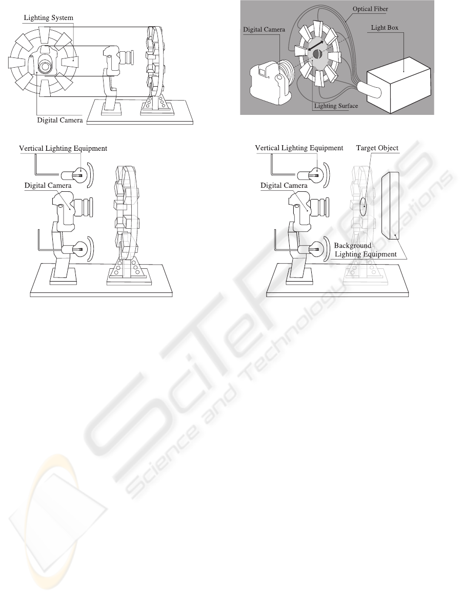
Figure 4: Slit Lighting.
Figure 5: Slit Lighting structure.
Figure 6: Transition of Brightness under our slit-lighting
equipment.
Figure 7: Transition of Brightness under our slit-lighting
equipment.
color. The surface emits various colors depending on
the lighting condition. Being able to manipulate the
lighting condition allows modeling this kind of reflec-
tion pattern. Another example is transparency of the
target material. We in fact designed a lighting system
and transparency scanning technique using it to cap-
ture diffusion and transmission coefficients. This is
discussed in the following chapter.
We used a high-end consumer digital camera
(Canon EOS-1Ds Mark II) and SIGMA MACRO 50
mm F2.8 EX DG lens. The camera resolution is 5000
x 3400 pixels and the resulting depth data is also in
this resolution, which is almost unattainable in exist-
ing 3-dimensional scanners. Our system does not de-
pend on a specific function of a certain digital camera.
The current camera can be replaced by any kind of a
new product with higher resolution imaging capabil-
ity.
2.3 Capturing Other Physical Features
The lighting condition a sequence of images for gen-
erating all-focused image can be in any form for mea-
suring other physical features. By designing a pro-
prietary background illuminator, our system can also
capture transparency of the target object. This is an
element that did not exist in the conventional photog-
raphy.
In the natural world, there are semi-transparent
materials such as a glass, feather of insects. To
represent these semi-transparent objects in com-
puter graphics, it is indispensable to take into ac-
count transmission, refraction and diffusive reflection.
To deal with these optical characteristics of semi-
transparency in photography, it is needed to check
the materiality of the object corresponding to each
pixel of an image. However, it is time-consuming,
expensive and practically difficult. In existing re-
search, there are several methodologies proposed that
uses blue-screen to measure semi-transparency. In
fact, even with these methods, semi-transparency is
assigned to a virtual object in computer graphics by
empirical assessment of an engineer and an artist.
Also, diffusion effect, where a background image gets
blurred in accordance with the distance between the
background object and a foreground semi-transparent
object, is hardly considered. In case of need, an ob-
ject is modeled so that it appears to have a diffusion
effect. In this research, we propose a new methodol-
ogy to capture two characteristics of transmission and
diffusion effect of a thin semi-transparent object from
a series of photographic images and represent them in
computer graphics.
In general, transparency means the ratio of how
GRAPP 2007 - International Conference on Computer Graphics Theory and Applications
148
a foreground object is mixed with a background ob-
ject. Diffusivity means how the background object
gets blurred as the distance between the foreground
object and the background object increases. In the
current state of the industry, assigning these parame-
ters to 3-dimensional models for use in films and com-
puter graphics is empirically done and never seriously
considered. We succeeded in developing a system to
capture these parameters from a real object.
On top of this, the resulting scanned model is in
general 3D computer graphics format. Therefore, it
can be edited on various kinds of commercial 3DCG
software and also shown on general viewers such as
a regular 3D viewer software and Web3D viewer for
observation. Using a general format allows other
structural features such as internal structure captured
by X-ray inspector to be easily added to the captured
model.
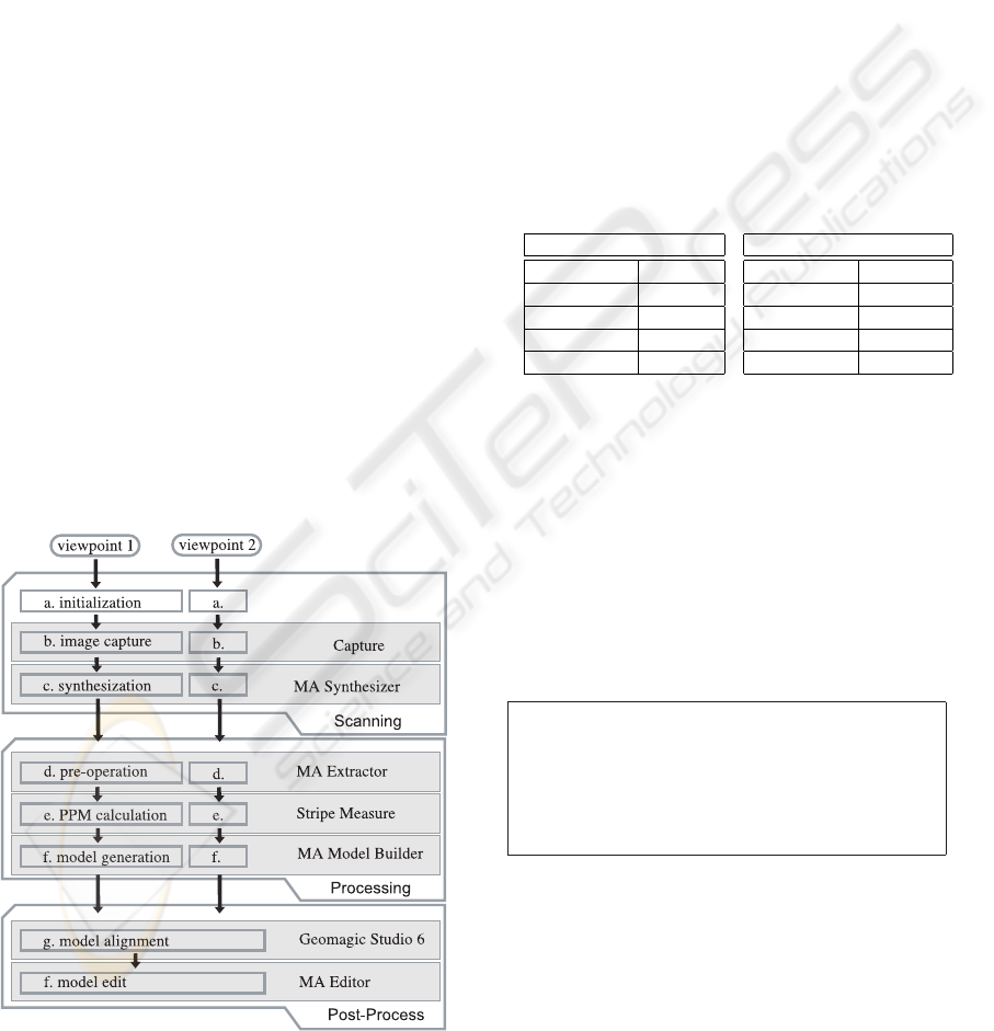
3 SCANNING PROCESS
Our Micro Archiving scanning process is mainly
composed of three parts in shown figure 8: scanning,
image processing and postprocessing. In the scanning
process, sequences of images are captured by our pro-
posed system. In the image processing, the sequences
of images are processed to extract 3-dimensional sur-
face shape, an all-focused image and a transparency
map. Finally, in the post-processing, these data are
EOS
Figure 8: Transition of Brightness under our slit-lighting
equipment.
combined together to output a 360 degree model and
texture data. Also the model data is converted into a
generic 3D model data format and also Web3D format
for rendering.
3.1 Initialization
Firstly the target object is set on the moving arm and
all the mechanical parts are set to be at the initial po-
sition. The slitlighting is set to illuminate the top of
the target object. The lens of the digital camera is also
set to focus on the illuminated part.
Camera parameter is also critical and it affects the
quality of the resulting model data. It needs to be fine-
tuned depending on what the target object is. How-
ever, we heuristically know that the following param-
eters are the best as default settings for an average
target object.
Table 1: Camera parameters.
For slit-lighting condition
Exposure 1.00 [sec]
Lens Aperture F/5.6
ISO 400
Shutter Speed 1.00 [sec]
Aperture F5.6
For strobo lighting condition
Exposure 1/160 [sec]
Lens Aperture F/8.0
ISO 100
Shutter Speed 1/160 [sec]
Aperture F8.0
After the initial calibration, all the steps of captur-
ing and processing are done by an automated script
program.
3.2 High-Resolution 3-dimensional
Imaging
Because focusing depends on the distance from the
camera to the corresponding part in the image, it is
possible to calculate how far from the camera each
pixel in a taken image is.
Img(x, y) : a pixel at the coordinate(x, y)
Img(x, y) : a pixel at the coordinate(x, y)
|Img(x, y)| : brightness of the pixel at the coordinate (x,y)
ImgAF : all-focused image
ImgD : depth image
ImgS
Index
: Index
th
image taken under the slit lighting.
ImgC
Index
: Index
th
image taken under the flash lighting.
For measuring 3D structure, the following process
is automatically done.
|ImgD(x, y)| = Index
where,
|ImgS
Index
(x, y)| =
max(|ImgS
0
(x, y)|, |ImgS
1
(x, y)|, ··· , |ImgS
n
(x, y)|)
This process is done by our proprietary software
called MA Synthesize.
A VIRTUAL ENVIRONMENT FOR ARCHIVING MICRO-PRESENCE WITH IMAGE-BASED MODEL
ACQUISITION
149
3.3 High-Resolution All-Focused
Imaging
For generating an all-focused image, the following
process is automatically done. For this process, depth
image that is acquired in the previous process is used
to specify the pixels used to construct the all-focused
image.
ImgAF(x, y) = ImgC
|ImgD(x,y)|
(x, y)
Our proprietary computer program synthesizes
these images to put together only focused pixels to
construct an allfocused image.
3.4 Transparency Capturing
In the natural world, there are semi-transparent mate-
rials such as a glass, feather of insects. To represent
these semitransparent objects in computer graphics,
it is indispensable to take into account transmission,
refraction and diffusive reflection(Figure 9).
Figure 9: Diffusive Effect.
To deal with these optical characteristics of semi-
transparency in photography, it is needed to check
the materiality of the object corresponding to each
pixel of an image. However, it is time-consuming,
expensive and practically difficult. In existing re-
search, there are several methodologies proposed that
uses blue-screen to measure semi-transparency. In
L
A
L
B
P
U
i-3
U
i-2
U
i-1
U
i
U
i+1
U
i+2
U
i+3
Q
i-3
Q
i-2
Q
i-1
Q
i
Q
i+1
Q
i+2
Q
i+3
Background Lighting
Foreground Lighting
Figure 10: Lighting Model.
fact, even with these methods, semitransparency is
assigned to a virtual object in computer graphics by
empirical assessment of an engineer and an artist.
Also, diffusion effect, where a background image gets
blurred in accordance with the distance between the
background object and a foreground semi-transparent
object, is hardly considered. In case of need, an ob-
ject is modeled so that it appears to have a diffusion
effect. In this research, we propose a new methodol-
ogy to capture two characteristics of transmission and
diffusion effect of a thin semi-transparent object from
a series of photographic images and represent them in
computer graphics.
The target object is fixed between the vertical
lighting system and the background illuminator. As
shown in figure 10, assuming that the vertical light-
ing is composed of a number of points U
i
and the
background illuminator is composed of points Q
i
, the
color Γ(x) = [x
R
, x
G
, x
B
]
T
which is observed at the
point x on the camerafs projection plane can be de-
scribed by Lambertfs cosine law and inverted square-
root law as follows.
γ(x) = κ
′
L
A
∞
−∞
∞
−∞
cos
arctan
q
X
′2
d
+Y
′2
d
Z
′
d
X
′2
d
+Y
′2
d
+ Z
′2
d
dX
′
d
dY
′
d
+
κL
B
∞
−∞
∞
−∞
cos
arctan
q
X
2
d
+Y
2
d
Z
d
X
2
d
+Y
2
d
+ Z
2
d
dX
d
dY
d
+ ιL
B
,
= 2πκ
′
L
A
+ 2πκL
B
+ ιL
B
.
(1)
Here, U
i
− P = [X
′
d
, Y
′
d
, Z
′
d
]
T
,Q
i
− P =
[X
d
, Y
d
, Z
d
]
T
κ
′
are diffusive reflection coefficients
when observed from the front side, κ is the diffusive
reflection coefficient when the semitransparent object
is observed from the backside and κ represents trans-
mission coefficient of the semi-transparent object
observed from the backside. It is assumed that the
brightness U
i
of the vertical lighting U
i
is composed
of uniform color elements L
A
= [L
A
, L
A
, L
A
]
T
and
the brightness Q
i
of the background illuminator
Q
i
is also composed of uniform color elements
L
B
= [L
B
, L
B
, L
B
]
T
.
Estimation of the color of semi-transparent object
Γ(P) and its diffusive reflection coefficient a The sum
of κ and ι is defined to be diffusive reflection coeffi-
cient a.
Using α, the equation (1) can be rewritten as fol-
lows.
Γ(x) = (1− α)Γ(P) + αL
B
, Γ(P) =
2πκ
′
1− α
L
A
.
(2)
Here, the point Γ(P) can be presumed to be a point
on the semi-transparent object P.
From the equation (2), By measuring the color
of the semi-transparent object Γ(x
W
) captured on a
white background, the color of the white background
L
W
, the color of the semi-transparent object Γ(x
G
)
captured on a gray background and the color of the
gray background L
G
, it is possible to calculate Γ(P)
and α shown in the table 2.
GRAPP 2007 - International Conference on Computer Graphics Theory and Applications
150
Estimation of diffusive reflection coefficient κ and
transmission coefficient ι, acquired α split into diffu-
sive reflection coefficient κ and transmission coeffi-
cient ι.
With an object that has a known diffusive reflec-
tion coefficient, it is possible to measure κ
′
of a semi-
transparent object. In our method, a target object is
assumed to be a very thin object. Therefore, it is as-
sumed that κ can be approximated to κ
′
as long as it
does not exceed α and κ, ι are approximated by the
following equation.
κ
′
= min(α, κ), ι = α − κ
B
.
(3)
Acquired κ, ι are shown in the table 2.
Table 2: Acquired transparency maps of a sheet of japanese
hand-made paper.
Img(L
W
) Img( Γ(x
W
)) Img(L
G
) Img(Γ(x
G
))
Img(Γ(P)) Img(α) Img(κ) Img(ι)
3.5 Rendering
To render with acquired coefficients, three images,
the rendered image of the semi-transparent object
Img( Γ(P)), the image blurred in accordance with the
distance between the background object and the semi-
transparent object Img(Blur(L
B
)) and the background
image Img(L
B
), are prepared. As shown in the table
2, Img(α), Img(κ), Img(ι) are applied to the blending
map of each image.
We proposed a method for measuring diffusive re-
flection coefficient and transmission coefficient from
photographic images and a rendering method for
them. By this, it became possible to easily mea-
sure pixel-by-pixel transmission and diffusion effect
from a photography. It also became possible to repre-
sent diffusion effect, which has been hardly consid-
ered in conventional computer graphics. Since we
can not exactly know diffusive reflection coefficient
and transmission coefficient, which this paper deals
with yet, the validity of our method has not yet been
fully proved. However, because elements needed for
photo-realistic computer graphics are variables rela-
tive to neighboring pixels, our method is expected to
be highly effective.
transparency map
all-focused image
rendered images
Figure 11: Examples of scanned transparency map and ren-
dered images.
4 POST PROCESS
4.1 Integrating Coordinate System
Our system scans a target object from multiple direc-
tions. The multiple model surfaces are in different
coordinate systems and needed to be in a common
coordinate system to be aligned and merged. Our
technique does this by calculating how big in a cap-
tured image an object in a known size is represented.
This size is represented in a unit called PPM(pixels
per millimeter). The XY coordinates of the scanned
all-focused image and the Z coordinate of the depth
data are converted into a common 3-dimensional co-
ordinate by this parameter.
4.2 Mesh Alignment
Because our system can capture a target object from
only one direction at one time. To create a model that
can be observed from 360 degree, mesh data from
multiple direction have to be combined seamlessly.
Our system utilizes a commercial software called Ge-
omagic Studio 6. This software is used to align sur-
face models captured from different angles.
4.3 Mesh Merging
Once the surface models are aligned, they are merged
together to form a continuous surface. This opera-
A VIRTUAL ENVIRONMENT FOR ARCHIVING MICRO-PRESENCE WITH IMAGE-BASED MODEL
ACQUISITION
151
tion is done by our proprietary software called Micro
Archiving Mesh Editor.
Figure 12: Mesh aligning.
5 RESULTS
The current maximum scannable texture size is 5000
x 3400 pixels and our technique allows maximum
model data size of about 30,000,000 bytes (2.3 G
bytes).
For a target object in the size of 2.0 cm long, it
takes about 30 minutes to scan from one direction.
Usually to create 360 degree model, a target object
needs to be scanned from 8 directions. Therefore it
takes 240 minutes to scan the whole target object.
6 APPLICATIONS
6.1 Web3d/webstereo
On the current broadband Internet, Web3D technol-
ogy can potentially be used for various kinds of
applications such as online museums and multime-
dia database systems for both general public and re-
searchers specialized in a certain region. This fact
will necessitate rapid development of content for such
applications. Our Micro Archiving technology pro-
vides a technical solution. We created some Web3D
contents public on an Internet website where any-
body can observe and interact with high-resolution 3-
dimensional models. Users can freely zoom into a
detail to observe the minute structures.
Figure 13: Web3D contents.
6.2 Animation
The 3-dimensional models captured by our method
can be edited on many kinds of 3D computer software
for various purposes. One possible application would
be 3D computer animations. Such as digital films,
games and other many different kinds of entertain-
ment media that requires photorealistic 3-dimensional
models.
Figure 14: Animation sequence.
6.3 Academic Research
Entomology, which is a study on insects, often re-
quires real specimens of insects to conduct a research.
The models that can be captured by our methodol-
ogy has enough resolution, accuracy and dense infor-
mation including color, shape and transparency. We
also succeeded in combining X-ray scanning struc-
tural data. With our proprietary interaction software,
anybody can interact with and observe the 3D models.
This would be strong application software for aca-
demic researchers who always need access to speci-
mens.
Figure 15: A proprietary interactive viewer.
REFERENCES
Levoy, M. (2000). The digital michaelangelo: 3d scanning
of large statues. In Proceedings ACM SIGGRAPH
2000. ACM.
Nayer, S. K. and Nakagawa, Y. (1994). Shape from fo-
cus. In IEEE Transactions on Pattern Analysis and
Machine Intelligence. IEEE Computer Society.
GRAPP 2007 - International Conference on Computer Graphics Theory and Applications
152
