
TOWARDS INTELLIGENT VR
Multi-Layered Semantic Reflection for Intelligent Virtual Environments
Marc Latoschik and Christian Fr
¨
ohlich
AI & VR Lab, Bielefeld University, PO 100131, 33501 Bielefeld, Germany
Keywords:
Intelligent Virtual Environment framework, Simulation Core, Software Design.
Abstract:
This paper introduces semantic reflection, a novel concept for a modular design of intelligent applications.
SCIVE, a simulation core for intelligent Virtual Environments (IVEs), provides semantic reflection on mul-
tiple layers: SCIVE’s architecture grants semantic driven uniform access to low-level simulation core logic,
to specific simulation modules’ application definitions, as well as to high-level semantic environment de-
scriptions. It additionally provides a frame to conveniently interconnect various simulation modules, e.g.,
for graphics, physics, audio, haptics, or AI etc. SCIVE’s Knowledge Representation Layer’s base formalism
provides the central organizing structure for the diverse modules’ data representations. It allows bidirectional
knowledge driven access between the modules since their specific data structures and functions are transi-
tively reflected by the semantic layer. Hence SCIVE preserves, integrates and provides unified access to the
development paradigms of the interconnected modules, e.g., scene graph metaphors or field route concepts
etc. well known from todays Virtual Reality systems. SCIVE’s semantic reflection implementation details are
illustrated following a complex example application. We illustrate how semantic reflection and modularity
support extensibility and maintainability of VR applications, potential for automatic system configuration and
optimization, as well as the base for comprehensive knowledge driven access for IVEs.
1 INTRODUCTION
Developing sophisticated Virtual Reality (VR) appli-
cations can become extensively complex. Rich be-
lievable worlds demand the integration of various
simulation aspects, e.g., for the simulation of graph-
ics, sounds, and physics. Furthermore, smart graph-
ics, intelligent environments, games, or ubiquitous
computing etc., demand the integration of Artificial
Intelligence methods. AI provides fundamental meth-
ods for (path) planning, application logic, or semantic
environment descriptions and more. Such methods
support tasks ranging from advanced multimodal in-
teractions to simulated physical object behavior, e.g.,
required for virtual construction or the simulation of
autonomous entities (agents or NPCs – non-player
characters) with cognitive capabilities.
Since visual perception is considered a primary
sense for immersion, many real-time VR applica-
tions center around the graphics representation. Scene
application design
simulation core logic
specific modules' definitions
scene entities
Figure 1: Semantic reflection maps the data and object rep-
resentations from various simulation applications’ layers to
a unified semantic knowledge representation.
graph tools like OpenGL Performer (Rohlf and Hel-
man, 1994), Open Inventor (Strauss and Carey, 1992),
Open Scene Graph, OpenSG (Reiners et al., 2002) or
X3D (ISO/IEC, JTC 1/SC 24, 2004) follow an hier-
archical scene structure which additionally provides
performance optimizations, e.g., for picking, culling
or state sorting. Extension mechanisms, field route
data propagation networks as well as scripting sup-
249
Latoschik M. and Fröhlich C. (2007).
TOWARDS INTELLIGENT VR - Multi-Layered Semantic Reflection for Intelligent Virtual Environments.
In Proceedings of the Second International Conference on Computer Graphics Theory and Applications - AS/IE, pages 249-259
DOI: 10.5220/0002081302490259
Copyright
c
SciTePress

port the design of customized nodes and application
graphs using rapid prototyping mechanisms.
Purpose-built VR development tools extend these
concepts with VR-specific key features: First,
input/output device customizability and embed-
ding (Preddy and Nance, 2002) is mandatory,
see, e.g., AVANGO (Tramberend, 1999), Light-
ning (Blach et al., 1998), VR Juggler (Bierbaum
et al., 2001) or commercially available ones like the
CAVELib
TM
or the WorldToolKit
R
. Second, network
distribution features are commonly integrated, e.g., in
AVANGO (Tramberend, 1999), MASSIVE 3 (Green-
halgh et al., 2000), DIVE (Hagsand, 1996)(An-
thony Steed, 2004) or Net Juggler. They either allow
distributed rendering on cluster architectures, hence
again output device support, or to develop shared vir-
tual environments. Third, application programmers
often require an entity centered access to world states
or world logic which is often realized using event
mechanisms, see, e.g., Lightning (Blach et al., 1998).
The provided scene and data propagation graphs
initially offer a useful representation. Complete sim-
ulation applications are build around the graph struc-
tures utilizing node inheritance and routing methods.
While well motivated in the beginning, such a de-
sign leads to a close coupling between the applica-
tions’ content and the specific design tool. This is
a source of several drawbacks now known for some
time (Bethel et al., 1999) (Arnaud and Jones, 1999),
e.g., w.r.t. a clean software design: extensibility and
portability are especially required during the integra-
tion or replacement of additional simulation modules
to render animations, sounds, physics, haptics, or AI.
Such modules are either included on a case by case
base, or they are integrated a priori into holistic ar-
chitectures as found in many 3D game engines like
the Doom 3 Engine, the Unreal Engine 3, the Source
Engine, the C4 Engine or the CryENGINE
TM
Extensible and portable architectures modularize
VR system implemetation (Kapolka et al., 2002)(Al-
lard et al., 2004) . The goal is a decoupling of specific
application content from the internals of a simula-
tion engine—a challenging task due to the potentially
close data coupling but distinct data representations
and data-flow in the various modules. This requires an
abstract high-level interface specification for both, the
included simulation modules as well as their internal
data flow and hence the inter-module data exchange.
Here, on a fine grained implementation level, ob-
ject oriented programming (OOP) paradigms provide
the concept of reflection to support extensible and
portable software designs, e.g., for dynamic program-
ming approaches. Reflection provides meta-access to
an object’s API during runtime which enables calling
objects to automatically query target objects’ capabil-
ities and adjust to their interfaces.
Descending from a different line of research,
a principle found in intelligent virtual environ-
ments (Luck and Aylett, 2000) is a semantic represen-
tation of scene content (Soto and Allongue, 2002)(Pe-
ters and Shrobe, 2003)(Latoschik and Schilling,
2003)(Kalogerakis et al., 2006)(Lugrin and Cavazza,
2007) to provide knowledge driven access to the
scenes’ entities, an approach similar to current seman-
tic web efforts. Lately, semantic models have also
gained interest in OOP (Meseguer and Talcott, 2002)
as an abstract description for object reflection. Fol-
lowing these directions, we propose a concept called
semantic reflection for intelligent virtual environ-
ments. Semantic reflection derives from two princi-
ples: The well-known reflection principle of OOP lan-
guages and the semantic entity descriptions provided
by AI based knowledge representations.
Semantic reflection provides ontology based dy-
namic access to all modules and entities in a simu-
lation application during runtime. Integrated into a
modular architecture, semantic reflection has to be in-
corporated on multiple layers (illustrated in figure 1):
First, it has to reflect the simulation core’s logic, e.g.,
which modules are incorporated and how data access
and flow of control is defined between these modules.
Second, it has to reflect the modules’ specific repre-
sentations, e.g., it should allow scene graph, applica-
tion graph, or physics access on the semantic layer.
Third, it has to reflect on the scenes’ entities on the
conceptual layer as motivated from IVE research. To
provide a modular simulation engine with such ca-
pabilities, the engine has to take specific care of its
semantic reflection binding. In contrast to monolithic
designs of programming languages, here, semantic re-
flection has to map data representations and interfaces
from different modules under one layer while bind-
ing them together in a high performance environment.
The following section will illustrate the implementa-
tion of semantic reflection using SCIVE, a simulation
core for intelligent virtual environments.
2 ARCHITECTURE OVERVIEW
The following example application illustrates pro-
totypical tasks during the design of rich interactive
worlds and SCIVE’s support through its semantic re-
flection based architecture: The goal is the simulation
of an autonomous agent in a Virtual construction ap-
plication in which users and agent can freely interact
with the environment and with each other, i.e., using
miscellaneous input devices (in case of the users), di-
GRAPP 2007 - International Conference on Computer Graphics Theory and Applications
250
rect manipulation, and multi-modal input. User and
agent should be virtually embedded into the environ-
ment. They should be able to perceive their environ-
ment (and each other) while their actions should pro-
duce believable consequences.
graphics
physics
ani-
mation
inter-
action
cog-
nition
world
state
constr.
Figure 2: Required modules for the example application.
All five modules contribute to, and receive data from an
overall world state.
A functional decomposition suggests an architec-
ture where dedicated modules process graphics con-
tent, agent’s perception and cognitive capabilities (in-
put and reasoning), animation planning and genera-
tion (output), physics simulation, as well as constraint
solving and user interaction as illustrated in figure 2.
Note that a functional decomposition allows for dif-
ferent modules to be based on the same software tool
or library, as is the case for the constraint and inter-
action module which both will depend on the same
generalized application graph library.
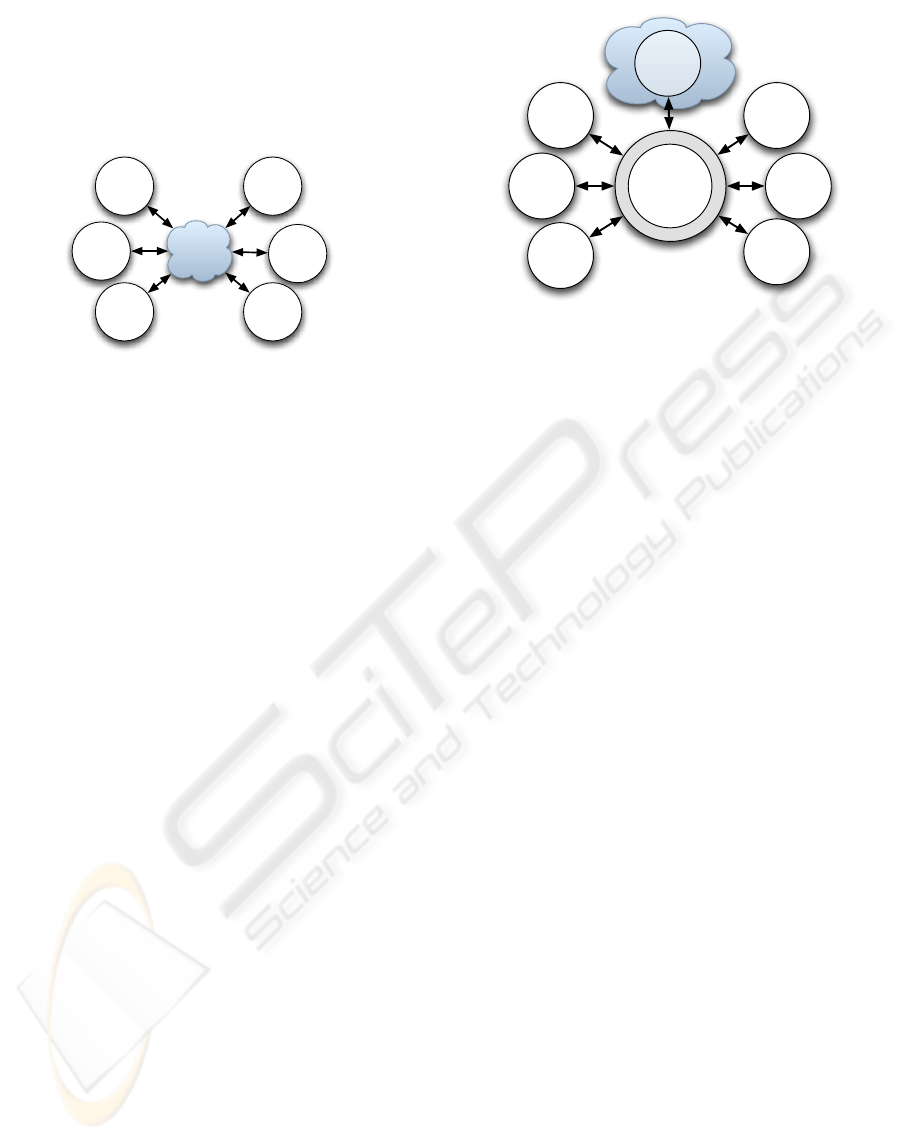
SCIVE’s core logic layer (see figure 1) enables
interconnections of arbitrary simulation modules to
exchange data with each other from single entity at-
tributes to complete world states as illustrated in fig-
ure 3. In this architecture, the world state as depicted
in figure 2 looses its central status. Technically, it is
handled as just an ordinary module with its own world
representation to be kept in synchrony. Since an at-
tribute’s data representation may be highly idiosyn-
cratic per module, we have developed a general data
exchange facility (Heumer et al., 2005).
The provided interconnection schemes range from
simple loose coupling to tight close coupling. In the
first case, a given module is infrequently contributing
to an overall world state, i.e., the module’s simulation
results might only access down to one of an entity’s
attributes once in a while with respect to the main sim-
ulation rate. In the second case, a module might ac-
cess the complete world state, every entity and every
attribute for every main simulation step performed.
Initialization and data flow between modules is
controlled by a temporal synchronization facility
(see section 4). It handles system bootstrapping and
data access order of the modules and hence implicitly
graphics
physics
ani-
mation
inter-
action
cog-
nition
data
exchange
&
synchroni-
zation
constr.
KRL
semantic
reflection
Figure 3: Conceptual interconnection scheme: Every re-
quired module is able to exchange data with every other
module ranging from single entity attributes to complete
world states. This requires facilities for data exchange and
control flow.
handles the multiple-database problem. It triggers the
modules’ local simulation loops asynchronously and
controls the following data collection, conflict res-
olution, and data propagation steps. Note that this
architecture specifically provides performance boosts
on parallel architectures.
3 SEMANTIC REFLECTION
LAYER
A net of interconnected entity definitions implements
semantic reflection in SCIVE. It provides a knowl-
edge representation layer (KRL) that ties the dis-
tributed world representations together. Every appli-
cation object and world entity from the three layers
(see figure 1) is mirrored by a custom-built semantic
net base formalism (Latoschik and Schilling, 2003).
Its low-level C++ implementation provides an event
system that guards read/write accesses from the con-
nected modules to the specific attributes.
Initially, all required modules are augmented with
a wrapper API which provides the necessary links to
the core logic as well as the initial bindings between
the modules’ objects and entities and their seman-
tic reflection layer counterparts. The KRL interlinks
these counterparts—ordinary semantic net nodes—
with the other modules’ representations while node
slots additionally provide a storage facility for at-
tribute values. The KRL knowledge model strictly
follows a common ontology, hence reading out at-
tribute values or traversing the relations from these
specific interlink-nodes can rely on a given schema
while the interlink nodes provide a logical entity in-
terface therefor called semantic entities. This seman-
TOWARDS INTELLIGENT VR - Multi-Layered Semantic Reflection for Intelligent Virtual Environments
251

tic reflection provides a knowledge driven, unified ac-
cess to distributed data representations significantly
enhancing standard OOP reflection.
SCIVE: data exchange & synchronization
KRL
world
state
graphics representation
user
rep.
agent
rep.
: virtual sensor/actors,
displays
: scene representation
inter-
action
anim.
cogn.
agent
user
Figure 4: Application layout 1: Embedding of u ser interac-
tion and agent perception into the graphics scene, which in
turn is linked via SCIVE to the KRL by special node types
(see text).
A pointed out, content creation as well as applica-
tion logic can be accessed bidirectionally. For back-
ward compatibility, application designers are permit-
ted to implement a required function in a specific
module. SCIVE’s inter-module wrappers also in-
clude mappings from the KRL’s semantic entities
to the modules’ object models—usually via multiple
inheritance—which then have full access to all appli-
cation objects and entities as well as to their seman-
tic descriptions. Figure 4 illustrates perception and
action embedding following the example application.
Both, the artificial agent as well as the user are repre-
sented by specific semantic entities embedded in the
graphics module (depicted for the nodes with dotted
lines to the KRL). Semantic entity nodes are directly
placed into the scene graph at the appropriate graph-
ics entities. This results in a strong dependence to the
used graphics engine and hence complicates reusabil-
ity and portability.
In contrast to that, SCIVE promotes discrete ap-
plication logic definition via direct KRL-access which
provides all modules’ functionality by its semantic re-
flection while providing independence from specific
modules and their underlying software. As illustrated
in figure 5, this design avoids specific module depen-
dencies as depicted in figure 4. Even though the KRL
is now located as a type of a central conceptional rep-
resentation, the modules are all interconnected via the
SCIVE facilities. Hence, dependencies are largely
minimized and modules can be exchanged with only
minor modifications. Since the KRL reflects the over-
all system down to the internal simulation core’s con-
figuration, even fine-grained control and data flow is
now available during abstract application design.
user
rep.
agent
rep.
inter-
action
anim.
cogn.
phy-
sics
KRL - world state
SCIVE
graphics
Figure 5: Application layout 2: SCIVE’s KRL centered in-
terconnection of user interaction, agent perception, anima-
tion, and physics modules (see text).
The benefit of semantic reflection can be demon-
strated following our example and the application lay-
out from figure 5. One solution for the implementa-
tion of the agents visual perception is the design of
a sensor which automatically tracks objects in its di-
rection and range. The sensor should work for every
frame, hence it must be linked to the application stage
of the program. Such specialized sensors are often
implemented as graphics nodes. This is reasonable
since graphics node traversal is synchronized with the
application and, embedded as a node, a sensor has au-
tomatic access to the spatial arrangement of the sur-
rounding scene (including the virtual user representa-
tion). Similar approaches are often followed for inter-
action nodes, e.g., draggers or interpolators, etc.
Parametrization of these nodes has to be defined,
e.g., which objects a dragger should and technically
could drag, or the target objects for the view sensors.
One obvious solution is realized by reflection, i.e.,
by using the dynamic runtime-type system available
with most graphics engines. By creating objects of a
specific type, the sensors or draggers etc. can auto-
matically detect compatible target nodes. Such an ap-
proach is cumbersome since it—using compiled pro-
gramming languages like C or C++—requires source
editing and recompilation which largely limits its use-
fulness. Since the KRL can be read/written during
runtime, it can capture this type of data to a large
amount.
For example, in typical applications we don’t want
GRAPP 2007 - International Conference on Computer Graphics Theory and Applications
252

our agent to monitor every entity in a rich environ-
ment, since most of the objects might be irrelevant to
a given task. Hence, the view sensor only searches
for entities which have a given semantic tag, i.e.,
is agent observable. Now, the view sensor pro-
cesses the KRL for every simulation step to collect all
entities it should monitor since it ”knows” what it has
to look for. The KRL is specifically tuned for fast
entity based per attribute access using an extensive
internal hashing. Having collected all target objects,
bidirectional semantic reflection enables the sensor to
easily reach through and read the position data of the
entities for its local spatial ordering.
Runtime type systems are often limited in terms
of their expressiveness, i.e., they are designed to re-
flect the specific modules object model which is often
limited to plain hierarchies and—to some degree—
multiple inheritance. Proprietary implementations
could of course represent semantic object and entity
information as well, but in absence of a unified layer
that again would require module specific low-level
coding strategies and efforts. Yet, such an approach
could not offer an inter-module knowledge represen-
tation and access as provided by the KRL’s seman-
tic net which additionally provides an expressive base
formalism tailored for semantic information.
3.1 Knowledge Definition
The KRL provides SNIL (Semantic Net Interchange
Language) as a high level XML-based descrip-
tion language for content definition. The KRL
supports knowledge-base modularization via sub-
domains which allow a modular knowledge engineer-
ing design, e.g., quite useful during the design phase
or as a facility of inspection, while they still pro-
vide inter-domain relations using ordinary relations.
The following example fragment illustrates how spe-
cific modules’ definitions as well as simulation core
logic is conveniently defined using one unified rep-
resentation language. The first example uses three
sub-domains to structure modules’ specific represen-
tations, one for the central KRL entities, and one each
for the graphics and the physics entities:
<?xml version="1.0" standalone="no" ?>
<semantic-net>
<subdomain name="KR-Central"/>
<subdomain name="SG"/>
<subdomain name="PHYS"/>
<relationtype name="is-a" type="Default">
<transitive />
</relationtype>
<relationtype name="inst-of" type="inst-of"/>
<relationtype name="has-gfx" type="Default"/>
<relationtype name="has-phys" type="Default"/>
</relationtype>
<node name="landscape" type="Default">
<in-subdomain name="KR-Central"/>
</node>
<node name="landscape-gfx" type="Default">
<in-subdomain name="SG"/>
<slot name="File" type="string"
inheritanceType="Attribut" value="room.iv"/>
</node>
<node name="landscape-phys" type="Default">
<in-subdomain name="PHYS"/>
<slot name="File" type="string"
inheritanceType="Attribut"
value="share/landscape-phys.xml"/>
<slot name="Name" type="string"
inheritanceType="Attribut" value="Ground"/>
<slot name="CaName" type="string"
inheritanceType="Attribut" value="GroundCa"/>
</node>
<relation typeName="has-gfx" id="1">
<start-node nodeName="landscape"/>
<end-node nodeName="landscape-gfx"/>
</relation>
<relation typeName="has-phys" id="2">
<start-node nodeName="landscape"/>
<end-node nodeName="landscape-phys"/>
</relation>
</semantic-net>
The next fragment defines parts of SCIVE’s core
logic. Here, the KRL reflects general system setup
and module specification where the semantic net is
used to specify the simulation modules, their pa-
rameters and features (illustrated for one simulation-
module):
<subdomain name="SC"/>
<relationType name="has-module"
type="Default"> </relationtype>
<relationType name="has-feature"
type="Default">
</relationtype> <node name="System_Configuration"
type="Default" id="1">
<in-subdomain name="SC" />
</node>
<node name="Physics" type="module" id="2">
<in-subdomain name="SC"/>
<slot name="configuration_path" type="string"
inheritanceType="Attribute"
value="xml_data/" />
<slot name="priority" type="string"
inheritanceType="Attribute" value="high" />
<slot name="load-time" type="number"
inheritanceType="Attribute" value="3" />
<slot name="frequency" type="number"
inheritanceType="Attribute" value="20" />
</node>
<node "Collision_Detection" type="feature" id="3">
<in-subdomain="SC"/>
<slot name="Method" type="string"
inheritanceType="Attribute"
value="Raycast" />
</node
<relation typeName="has-module" id="4">
TOWARDS INTELLIGENT VR - Multi-Layered Semantic Reflection for Intelligent Virtual Environments
253
<start-node nodeName="System_Configuration"/>
<end-node nodeName="Physics"/>
</relation>
<relation typeName="has-feature" id="5">
<start-node nodeName="Physics"/>
<end-node nodeName="Collision_Detection"/>
</relation>
Instantiation of a new System Configuration (SC)
subdomain is followed by the definition of nec-
essary relations. The relations has-module and
has-feature are later used to connect the root-node
(System Configuration) with it’s modules respec-
tively the modules with their provided features. Mod-
ule definitions require some parameters, which are
given as slot-values inside a node environment. These
parameters configure the modules and their intercon-
nection, and are used for the temporal synchroniza-
tion, which will be discussed in section 4.
”Features” are introduced as another type of
nodes. Existence and implementation of specific fea-
tures can differ from module to module. In case of
the example, a given feature of a physics module is
the Collision Detection. Along with the existence
of a feature, some details, such as the Method, are
specified as slot-values. On the basis of the existence
of features and their capabilities, modules can be se-
lected for an application.
4 TEMPORAL
SYNCHRONIZATION
Since the different simulation modules run asyn-
chronously and each with a different update fre-
quency, these components have to be synchronized
to ensure a consistent state of the simulated world.
The different clock rates are necessary to guarantee
accurate computation of the specific simulation-data.
For example, while the graphics renderer computes
one frame the physics simulator may has to compute
twenty internal steps to ensure a mathematical accu-
rate result. These differences become even clearer
when we take a look at haptics feedback. A mod-
ule computing haptics feedback needs a minimum up-
date frequency of approximately 1000 hertz to give
the user a realistic sensation. Hence inter-module syn-
chronization becomes important to keep module data
consistent with each other.
The temporal synchronization within the SCIVE-
System is divided into two basic areas. While the
macrotemporal area covers the steps required at the
initial startup of the system, as well as those steps ex-
ecuted when loading new modules at runtime, the mi-
crotemporal area includes those which are executed
for every master simulation step. The following ex-
emplifies the necessary steps of the microtemporal
area and shows how they can be reflected on the
semantic level, using Allen’s temporal interval rela-
tions.
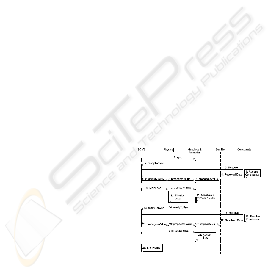
4.1 Microtemporal Processing
Microtemporal steps necessary for computing one
simulation frame in SCIVE’s modular architecture
are illustrated for an example setup in the sequence
diagram in figure 6. The bracketed bold-faced
numbers—(i)—represent the numbers according to
the various steps in the sequence diagram.
Microtemporal processing within SCIVE will be
illustrated for an example application which centers
around the semantic net as the central world state.
Hence, the first step in the sequence-diagram dis-
played in figure 6 sends a sync-signal to the SemNet-
module (1). The sync-signal is answered by a ready-
signal (2) from the semantic module. Before SCIVE
propagates the simulation data to all connected mod-
ules, existing contraints are resolved (3-5). These
constraints can be resolved by SCIVE’s built-in filter
system, or by any other dedicated simulation-module
(see section 5). After this, SCIVE propagates the data
to all modules (6-8). As a result, all simulation mod-
ules now initially work on the data, which was gener-
ated in the prior master simulation step, and resolved
by the dedicated mechanism.
Figure 6: Microtemporal processing of SCIVE.
The next steps consist of the parallel computations
of the simulation modules (in this case the Physics-
and the Graphics/Animation-module). Steps num-
ber (9-10) start the processing of these modules inside
their own update frequencies. The processing itself is
GRAPP 2007 - International Conference on Computer Graphics Theory and Applications
254

displayed in (11-12). Once the modules finish compu-
tation, they synchronize their results with each of the
other modules, again through SCIVE’s data-exchange
mechanism and again with respect to constraint reso-
lution (13-20). The final step in the microtemporal
processing is the rendering of the computed scene.
SCIVE tells the renderer to display the scene (21) and
the graphics renderer executes its render-loop (22).
4.2 Semantic Reflection of Temporal
Processes
The temporal processes described in the previous sec-
tion are as well reflected on the KRL as part of
the simulation core’s internal logic. The following
code depicts a SNIL representation of the temporal
processes using Allen’s temporal interval relations
(Allen, 1984):
<subdomain name="TS"/>
<relationType name="before" type="Default">
</relationtype>
<relationType name="meets" type="Default">
</relationtype>
<relationType name="during" type="Default">
</relationtype>
<node name="Simulation_Frame" type="action" id="1">
<in-subdomain name="TS" />
</node>
<node "Graphics_App" type="action" id="2">
<in-subdomain="TS"/>
</node>
<node "Graphics_Rendering" type="action" id="3">
<in-subdomain="TS"/>
</node>
<node "Constraint_Resolution" type="action" id="4">
<in-subdomain="TS"/>
</node>
<node "Propagate_Data" type="action" id="5">
<in-subdomain="TS"/>
</node>
<node "Sync_Data" type="action" id="6">
<in-subdomain="TS"/>
</node>
<relation typeName="during" id="7">
<start-node nodeName="Simulation_Frame"/>
<end-node nodeName="Graphics_App"/>
</relation>
<relation typeName="before" id="8">
<start-node nodeName="Graphics_App"/>
<end-node nodeName="Sync_data"/>
</relation>
<relation typeName="meets" id="9">
<start-node nodeName="Sync_Data"/>
<end-node nodeName="Constraint_Resolution"/>
</relation>
<relation typeName="meets" id="10">
<start-node nodeName="Constraint_Resolution"/>
<end-node nodeName="Propagate_Data"/>
</relation>
<relation typeName="before" id="11">
<start-node nodeName="Propagate_Data"/>
<end-node nodeName="Graphics_Rendering"/>
</relation>
The example only illustrates application- and ren-
der stage definitions for the Graphics&Animation-
module. Representation for other modules and stages
work analogously.
4.3 Built-in Conflict Resolution
The concurrent access to the central database by the
various simulation modules could lead to an inconsis-
tent world state resulting in wrong or unexpected be-
havior of entities, if the attribute would not be guarded
or controlled in some way. Here, SCIVE provides a
special type of a data propagation graph utilizing a
system of connections and filters. For example, in
a simple configuration filters can forward the output
of the physics module to one entity, a second en-
tity can be controlled by the skeletal animation, and
yet another entity can be controlled by the user in-
teraction. In more complex scenarios, the filters can
compute new values for controlled entity attributes
by combining outputs of two or more modules or fil-
ters. SCIVE offers various filters that can change at-
tribute values directly or indirectly, e.g., a developer
can choose whether he wants an object to be dragged
by directly setting the new position in all modules (in-
cluding the physics module) or by applying appropri-
ate forces generated by the physics engine. Filters can
be instantiated manually or by the various simulation
modules which allows automatic flow control by the
application logic, e.g., if the multi-modal interpreta-
tion module triggers a drag action, a filter is set in
place which binds the interaction target entity to the
interaction module.
The filter-based data-flow is provided by SCIVE’s
conflict resolution component. It is an optional facil-
ity but it provides the necessary functionality for the
design of complex interconnected applications. It can
be completely enabled and disabled on the fly. With
disabled conflict resolution, each value change will
be immediately applied to the central database and
the databases of the modules, overwriting all earlier
changes. With enabled conflict resolution, all value
changes (triggered as events by SCIVE) will be de-
layed until the beginning of the final render stage. In
this case, the requested state changes will be stored
to use them as input for the filter stage. During this
stage, filter can 1) forward an event, 2) combine it
with other events and the relating values, or 3) com-
pletely block it. The order of events is less important
for the conflict resolution since it applies filters with
TOWARDS INTELLIGENT VR - Multi-Layered Semantic Reflection for Intelligent Virtual Environments
255
respect to the event source and its simulating feature.
The last filter in the chain is connected back to the at-
tribute container in the main database. After the eval-
uation of filters and propagation of changes, all mod-
ules must be informed about the rejected changes.
This additional step is necessary, because the module
that has requested the change, has possibly already
changed its internal state and representation.
4.4 Filters
Connections and filters establish an event propagation
graph. They receive events they have registered for.
Filters can process computations on the signaled at-
tribute values and finally produce new signals. In ad-
dition, instead of returning events, a filter can trigger
execution of specific actions in the simulation mod-
ules, e.g., to apply some forces in the physics module
or to generate a new animation which simulates an
agent’s reaction to external influences (as eventually
triggered by the other modules). A certain required
action often can be implemented with different meth-
ods and hence filters. For example, dragging of an en-
tity can be implemented by setting the new position as
a result from the interaction module which basically
follows the user’s ”drag” hand or by applying some
forces by the physics module. In the basic SCIVE in-
terconnection, the interaction module can just change
the position where the actual action is determined by
the current filter. Since the desired action is decoupled
from the actual implementation, setup of this inter-
nal application logic is covenantally implemented on
a high level during runtime or initially using configu-
ration files. The following filters realize the required
functionality for the example application.
• Last module pass through. This is the same as if
no conflict resolution is done.
• Random module selection pass through.
• Specific module pass through.
• Prioritized module list selection. Pass the events
from a priority sorted list of modules. If queue is
empty for a chosen module, take the next lower
prioritized module.
• Physics module pass through. Apply forces to the
entity for all other events with position changes.
• Skeletal animation module pass through. Gen-
erate a dynamic animation and blend it with the
current animations for all other events with posi-
tion changes.
The user can implement additional filters e.g. for
calculating an average value of the incoming events.
The conflict resolution set-up defined for the exam-
ple application allows to simulate physical-based an-
imations on the fly and to mix them with motion cap-
tured or pre-calculated animation data. This exam-
ple illustrates SCIVE’s powerful extensibility which
is utilized at this point to produce believable inter-
actions of skeletal animated characters with the en-
vironment in real time. In order to react to physi-
cal forces, a physical representation of the character
is built up which, on the one hand, influences other
physical bodies and, on the other hand, reports the dis-
placement of the character caused by collisions back
to SCIVE. In case of a collision, the established filter
interconnection decides how to react to the displace-
ment. The agent could just drag the affected parts
back, wobble, or fall down. The reaction can depend
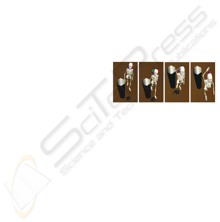
on the force and the place of the impact. Figure 7
shows the generated animation as result of a collision
between a character and a static as well as between a
dynamic object.
(a) (b) (c) (d)
Figure 7: The animated agent filter in action. The motion
captured animated agent collides with a relatively heavy
(the column) and a lighter (the stone) obstacle in its pre-
determined path. The collision signals the activation of an
animation blending filter which controls the colliding body
parts for the specific time interval whereas the collision ob-
jects stay under physics control.
4.5 Filter Application
SCIVE’s supports filter application via rules which
assign filters to certain scene parts. These parts can
have different granularities from one attribute of one
entity to all attributes in the scene. Prioritization of
rules ensures that attributes already connected by a
given rule will not be reconnected by lower prioritized
rules. For example, a scene with a skeletal animated
agent can be described by this two rules:
• Assign ”all properties of obj. A” to ”SkeletalAni-
mationFilter”
• Assign ”all properties in scene” to ”PhysicsOnly-
Filter”
The second rule doesn’t influence the object A (the
agent), because of the first rule’s higher priority. The
GRAPP 2007 - International Conference on Computer Graphics Theory and Applications
256

created filter graph can be changed on the fly by in-
serting and removing rules. To drag an entity X, a
new rule has to be installed just before the other two:
• Assign ”position of object X” to ”InteractionFil-
ter”
This results in the disconnection of the position at-
tribute of entity X from the ”PhysicsOnlyFilter” and
its connection to the ”InteractionFilter”. At the inter-
action end, this rule is simply removed to establish the
initial application logic. This prioritized application
of rules, which describe what the user wants to hap-
pen in the scene, provides a convenient way to create
and assign the—possibly—multitude of required fil-
ters. Each rule takes just few lines of code or script
that—at the end—defines complex filter graphs which
will now automatically be created and removed. This
lets application designer focus on application seman-
tics rather then to care about the proper connection of
filters and attributes.
4.6 Filter Definition on the Semantic
Level
The data propagation graph–including Filters–used in
the built-in conflict resolution system can be defined
on the knowledge representation Layer. To define
such a graph, a subdomain in the semantic net must
be specified in which specific nodes an relations are
created. The following shows a small example:
<subdomain name="CR"/>
<relationType name="has-input-node"
type="Default">
</relationtype>
<relationType name="has-output-node"
type="Default">
</relationtype>
<relationType name="has-filter" type="Default">
</relationtype>
<relationType name="has-cr-connection"
type="Default">
</relationtype>
<node name="crEntity1" type="crEntity" id="1">
<in-subdomain name="CR" />
</node>
<node "crNode1" type="crNode" id="2">
<in-subdomain="CR"/>
</node>
<node "crNode2" type="crNode" id="3">
<in-subdomain="CR"/>
</node>
<node "crFilter1" type="filter" id="4">
<in-subdomain="TS"/>
</node>
<relation typeName="has-input-node" id="5">
<start-node nodeName="crEntity1"/>
<end-node nodeName="crNode1"/>
</relation>
<relation typeName="has-filter" id="6">
<start-node nodeName="crNode1"/>
<end-node nodeName="crFilter1"/>
</relation>
<relation typeName="has-cr-connection" id="7">
<start-node nodeName="crNode1"/>
<end-node nodeName="crNode2"/>
</relation>
<relation typeName="has-output-node" id="8">
<start-node nodeName="crEntity1"/>
<end-node nodeName="crNode2"/>
</relation>
The root node in this example is the crEntity-
node. It is connected with two crNodes, one input-
and one output node. While the input node is the
entry for the data to the conflict resolution network,
the output is the exit which contains the conflict-
resolved data. Filters get connected to crNodes via the
has-filter-relation while crNodes are connected
with each other through the has-cr-connection-
relation. To concatenate the ”cr-network” with an en-
tity of the central knowledgebase the crEntity node
can be connected to the designated node. This is
done analogously to the connection with a physical
or graphical representation as seen in section 3.1.
5 INTERACTION AND
CONSTRAINTS
For applications similar to the example’s type, we
have developed a multimodal interaction module
which processes speech and gesture input. Interac-
tions can be initiated by a variety of uni- or multi-
modal user expressions. Their analysis and realiza-
tion provide another well motivated example that il-
lustrates the power of semantic reflection during the
access of semantic information from different mod-
ules and layers. Speech and gesture interpretation de-
pends on ontology and lexical bindings to identify the
required operations and entities whereas the interac-
tion realization has to access the module specific ob-
jects to set up the appropriate module structures for
the application graph. Both, gesture recognition as
well as interaction realization, are based on similar
metaphors using generalized application graphs.
The module’s integration engine compares all in-
coming signals from gesture and speech recognition.
If it detects the initiation of an operation, it follows
the semantic interlinks between the lexical informa-
tion extracted from the user’s verbal utterance to an
appropriate action concept in the interaction mod-
ule’s knowledge part. Since this directly reflects the
required application graph structures, the integration
engine automatically instantiates such a structure in
TOWARDS INTELLIGENT VR - Multi-Layered Semantic Reflection for Intelligent Virtual Environments
257

handle
user
representation
KRL - semantic reflection
inter-
action
constr.
constraint
transformation
of handle
propagate
movement
detect
grasp
instantiate
interaction
Figure 8: Interaction and constraint module (see text).
the interaction module. The resulting application
graph style interaction binding couples the movement
of the selected object in the KRL with the movement
of the user’s hand as depicted in figure 8.
Since this interaction binding builds a linear chain
from the sensor data of the hand position to the trans-
formation of the object, the interaction module can
be handled in the common way of trigger, collect and
propagate states of the simulation core. However the
filter layer of the data-exchange has to make sure that
the transformation of the object from the user inter-
action overwrites the transformation changes of the
other modules, e.g., the physics layer.
More complex application graphs can be estab-
lished by a dedicated constraint module (Biermann
and Wachsmuth, 2004). For example, mapping of
a user’s hand movements to a target object—let’s
assume a simulated steering wheel—should be re-
stricted to certain degrees of freedom to simulate ac-
curate kinematic object behavior. The constraint for
the handle only allows one rotation axis. If the move-
ment of the handle during the Interaction fails to sat-
isfy this constraint, the transformation of the handle
is restricted to the rotation by calculating the rota-
tional part of the movement and setting this as the
transformation of the handle in the KRL. Further con-
straints propagate the movement to other objects or
gears which are also modeled with constraints and
therefore can e.g. simulate a kinematic chain of a
steering mechanism (see figure 8).
The difference is the way these constraints are
solved during synchronization. Since these con-
straints should globally restrict the attributes of the
objects in the KRL, the execution of the constraint
module must be triggered after the evaluation of the
other modules of the simulation core. This requires
simulation core access from the specific constraint
module which is conveniently provided by the seman-
tic reflection layer. Since the temporal synchroniza-
tion is semantically defined using Allen’s temporal re-
lations, all that has to be done from the module side
is a modification of these structures on the semantic
layer to achieve the desired core logic behavior. On
the other hand, SCIVE’s open architecture provides
modules to also solve core specific tasks. This is addi-
tionally useful if we think of the conflict resolution fa-
cility which can be substituted, e.g., by the constraint
module developed to solve similar tasks as reflected
by the module’s features on the semantic layer.
6 CONCLUSION
This paper introduced semantic reflection as an archi-
tectural concept for developing intelligent interactive
applications. It provides a suitable abstraction layer
to develop reusable, extensible, and portable com-
ponents. Semantic reflection unifies the application
design from low-level simulation core layer to high-
level scene semantic using just one metaphor. As a
base design principle, semantic reflection has proven
to be extremely useful and very promising.
The modular architecture and the Knowledge
Representation Layer of SCIVE—a simulation core
for IVEs—provides bidirectional semantic reflection
to develop module specific code as well as module
independent components. Its inter-module data ex-
change and synchronization can conveniently be con-
figured on a high level which includes the defini-
tion of general application logic down to per-attribute
changes via the filter and rules concept.
SCIVE’s semantic reflection capabilities are ex-
plored in several areas from multi-modal communi-
cation in virtual environments to AI supported vir-
tual prototyping. Its capability to integrate physics,
animation, AI etc. for building intelligent agents is
currently utilized to design a large scale continuously
running virtual world for agent interactions as well as
for the development of a prototypical game engine.
Outlook: The potential of semantic reflection for ap-
plication design can only roughly be estimated right
now by the examples we have explored so far. Since
semantic reflection includes all layers, from simula-
tion core to environment description, it offers verti-
cal reach through between these layers. For exam-
ple, the simulation core could automatically use a
specific module’s functions, e.g., for an alternative
conflict resolution. A module, on the other hand,
could change the core’s behavior depending on its
own running processes. Redundant functions in dif-
ferent modules could automatically be selected w.r.t.
a quality of service attribute for the functions. Lately,
we have modeled an enhanced ontology of interac-
tions which is linked a) to a lexicon and b) to spe-
cific node arrangements which implement these inter-
actions using the interaction module.
GRAPP 2007 - International Conference on Computer Graphics Theory and Applications
258

Grounding the complete application from core
logic to the simulated environment to an adequate
ontology could greatly simplify application develop-
ment. It would provide the necessary semantic infor-
mation for intelligent tools, that, e.g., automatically
map their functions w.r.t. the available resources etc.
while, on the other hand, it would provide an implicit
knowledge representation for building intelligent Vir-
tual Environments.
REFERENCES
Allard, J., Gouranton, V., Lecointre, L., Limet, S., Melin,
E., Raffin, B., and Robert, S. (2004). Flowvr: a mid-
dleware for large scale virtual reality applications. In
Proceedings of Euro-par 2004, Pisa, Italia.
Allen, J. F. (1984). Towards a general theory of action and
time. Artificial Intelligence, (23).
Anthony Steed, E. F. (2004). Construction of collabora-
tive virtual environments. In Segura, M.-I. S., editor,
Developing Future Interactive Systems, number ISBN
1591404126, pages 235–268. Idea Group.
Arnaud, R. and Jones, M. T. (1999). Innovative software
architecture for real-time image generation. In Pro-
ceedings of the I/ITSEC Conference.
Bethel, W., Bass, C., Clay, S. R., Hook, B., Jones, M. T.,
Sowizral, H., and van Dam, A. (1999). Scene graph
apis: wired or tired? In SIGGRAPH ’99: ACM SIG-
GRAPH 99 Conference abstracts and applications,
pages 136–138, New York, NY, USA. ACM Press.
Bierbaum, A. D., Just, C., Hartling, P., Meinert, K., Baker,
A., and Cruz-Neira, C. (2001). VR Juggler: A Vir-
tual Platform for Virtual Reality Application Develop-
ment virtual platform for virtual reality application de-
velopment. In IEEE Virtual Reality 2001 conference
proceedings, pages 89–96, Yokohama, Japan. IEEE
Press.
Biermann, P. and Wachsmuth, I. (2004). Non-physical sim-
ulation of gears and modifiable connections in virtual
reality. In Proceedings of the fifth Virtual Reality In-
ternational Conference (VRIC 2004), pages 159–164,
Laval, France.
Blach, R., Landauer, J., Rsch, A., and Simon, A. (1998).
A Highly Flexible Virtual Reality System. In Future
Generation Computer Systems Special Issue on Vir-
tual Environments. Elsevier Amsterdam.
Greenhalgh, C., Purbrick, J., and Snowdon, D. (2000). In-
side massive-3: flexible support for data consistency
and world structuring. In Proceedings of the third in-
ternational conference on Collaborative virtual envi-
ronments, pages 119–127. ACM Press.
Hagsand, O. (1996). Interactive MultiUser VEs in the DIVE
system. IEEE Multimedia Magazine, 3(1).
Heumer, G., Schilling, M., and Latoschik, M. E. (2005).
Automatic data exchange and synchronization for
knowledge-based intelligent virtual environments. In
Proceedings of the IEEE VR2005, pages 43–50, Bonn,
Germany.
ISO/IEC, JTC 1/SC 24 (2004). X3d abstract. Technical
Report 19775-1:2004, ISO/IEC.
Kalogerakis, E., Christodoulakis, S., and Moumoutzis, N.
(2006). Coupling ontologies with graphics content for
knowledge driven visualization. In Proceedings of the
IEEE VR2006, pages 43–50.
Kapolka, A., McGregor, D., and Capps, M. (2002). A uni-
fied component framework for dynamically extensible
virtual environments. In Fourth ACM International
Conference on Collaborative Virtual Environments.
Latoschik, M. E. and Schilling, M. (2003). Incorporating
VR Databases into AI Knowledge Representations:
A Framework for Intelligent Graphics Applications.
In Proceedings of the Sixth International Conference
on Computer Graphics and Imaging. IASTED, ACTA
Press.
Luck, M. and Aylett, R. (2000). Applying Artificial Intel-
ligence to Virtual Reality: Intelligent Virtual Environ-
ments. Applied Artificial Intelligence, 14(1):3–32.
Lugrin, J.-L. and Cavazza, M. (2007). Making Sense of Vir-
tual Environments: Action Representation, Ground-
ing and Common Sense. In Proceedings of the Intelli-
gent User Interfaces IUI’07.
Meseguer, J. and Talcott, C. (2002). Semantic models
for distributed object reflection. In ECOOP 2002 -
Object-Oriented Programming: 16th European Con-
ference Malaga, Lecture Notes in Computer Science,
pages 1–36. Springer Berlin / Heidelberg.
Peters, S. and Shrobe, H. (2003). Using semantic networks
for knowledge representation in an intelligent environ-
ment. In PerCom ’03: 1st Annual IEEE International
Conference on Pervasive Computing and Communi-
cations, Ft. Worth, TX, USA. IEEE.
Preddy, S. M. and Nance, R. E. (2002). Key requirements
for cave simulations: key requirements for cave sim-
ulations. In WSC ’02: Proceedings of the 34th con-
ference on Winter simulation, pages 127–135. Winter
Simulation Conference.
Reiners, D., Voß, G., and Behr, J. (2002). OpenSG:
Basic Concepts. www.opensg.org/OpenSGPLUS/-
symposium/Papers2002/Reiners Basics.pdf.
Rohlf, J. and Helman, J. (1994). Iris performer: a high
performance multiprocessing toolkit for real-time 3d
graphics. In SIGGRAPH ’94: Proceedings of the 21st
annual conference on Computer graphics and interac-
tive techniques, pages 381–394, New York, NY, USA.
ACM Press.
Soto, M. and Allongue, S. (2002). Modeling methods for
reusable and interoperable virtual entities in multi-
media virtual worlds. Multimedia Tools Appl., 16(1-
2):161–177.
Strauss, P. S. and Carey, R. (1992). An object-oriented 3D
graphics toolkit. In Computer Graphics, volume 26 of
SIGGRAPH Proceedings, pages 341–349.
Tramberend, H. (1999). A distributed virtual reality frame-
work. In IEEE Virtual Reality Conference, pages 14–
21.
TOWARDS INTELLIGENT VR - Multi-Layered Semantic Reflection for Intelligent Virtual Environments
259
