
A SCALABLE GPU-BASED APPROACH TO SHADING AND
SHADOWING FOR PHOTOREALISTIC REAL-TIME AUGMENTED
REALITY
Claus B. Madsen and Rune Laursen
Computer Vision and Media Technology Lab, Aalborg University, Aalborg, Denmark
Keywords:
Augmented Reality, shadows, High Dynamic Range images, video see-through.
Abstract:
Visually realistic Augmented Reality (AR) entails addressing several difficult problems. The most difficult
problem is that of rendering the virtual objects with illumination which is consistent with the illumination of
the real scene. The paper describes a complete AR rendering system centered around the use of High Dynamic
Range environment maps for representing the real scene illumination. The main contribution lies in a novel,
physically-based approach to rendering shadows cast by virtual objects without changing the shadows already
present in the images of the real scene. The proposed approach effectively involves real-time estimation of the
diffuse albedos of the real scene, and essentially relighting these areas to take virtual shadows into account.
Another contribution lies in the fact that the proposed approach is designed to run on graphics hardware and
is scalable in the sense that it offers a simple way to balance performance with visual quality.
1 INTRODUCTION
Augmented Reality (AR) is the process of rendering
virtual objects into a video stream in real-time for in-
teractive applications. AR poses a number of inter-
esting rendering problems most important of which is
the issue of achieving rendering of virtual objects with
illumination which is consistent with the real scene il-
lumination.
The present work proposes some novel solutions
integrated into a complete AR rendering pipeline ex-
tensively based on GPU processing for ease of imple-
mentation and for performance.
1.1 Related Work
Most AR research focuses primarily on AR as an in-
terface and explores ways of using AR for various
interactive applications. This paper only concerns
graphics techniques to maximize the visual realism
of AR. Figure 2 provides an example of our system
being used to render a virtual sculpture into a natural
scene.
Some related research also focuses on achieving
realism with impressive results but at the cost of real-
time performance, (Debevec, 1998; Debevec, 2002;
Sato et al., 1999a; Sato et al., 1999b; Loscos et al.,
2000). Other research achieves real-time performance
but with rather low generality and questionable phys-
ical accuracy, (Kanbara and Yokoya, 2004).
Recently research has been performed in tech-
niques for real-time rendering of virtual objects with
illumination from environment maps, (Havran et al.,
2005; Barsi et al., 2005). Both these works offer a
technique for scene-constistent virtual object illumi-
nation, but neither attack the problem of enabling vir-
tual objects to cast shadows on the real environment.
The present paper addresses this problem.
The most closely related research is presently by
(Gibson et al., 2003). They demonstrate a powerfull
approach for rendering animated virtual objects into
still images with impressive results. Their approach
to rendering shadows involves a very fast implemen-
tation of a radiosity algorithm (which can be difficult
to implement for most people). Our work is focused
on augmentation into a live video stream, is based on
techniques (shadow maps) that are much easier to im-
plement, and in particular we address the problem of
”double shadows”. This problem is described subse-
quently.
252
B. Madsen C. and Laursen R. (2007).
A SCALABLE GPU-BASED APPROACH TO SHADING AND SHADOWING FOR PHOTOREALISTIC REAL-TIME AUGMENTED REALITY.
In Proceedings of the Second International Conference on Computer Graphics Theory and Applications - GM/R, pages 252-261
DOI: 10.5220/0002083602520261
Copyright
c
SciTePress
1.2 Addressed Problem Areas
The present work addresses a number of problems re-
lating to approaching photo-realism in real-time AR.
First of all we wish to achieve scene consistent illu-
mination/shading of virtual objects. We have chosen
to employ a High Dynamic Range environment map
based pipeline for this. Secondly, we wish to create a
unified method to handling shadows to avoid special
cases or loss of generality. In an augmented scene vir-
tual objects should be able to cast shadows on them-
selves and other virtual objects, real objects should be
able to cast shadows on virtual objects, and finally,
virtual objects should be able to cast shadows on real
objects. The latter case poses a severe problem in the
sense that in some areas the image of the real scene al-
ready contains shadows, so in these regions it would
be wrong to further reduce the intensity to encompass
a shadow cast by a virtual object. This is the dou-
ble shadow problem which is a very typical problem
for AR, (Jacobs et al., 2005). Even the very complex
technique presented in (Gibson et al., 2003) has slight
problems with double shadows judging by the exam-
ples given.
2 OVERVIEW OF APPROACH
This section first gives a description of the concrete
system which has been constructed followed by a list-
ing of the assumptions behind the proposed approach.
2.1 Description of System Setup
The goal has been to construct a real-time video see-
through Augmented Reality system, where virtual
objects are augmented seamlessly into a live video
stream and displayed on a computer monitor. To en-
sure very high quality registration between the real
and the virtual scene elements we have restricted the
system to have two rotational degrees of freedom.
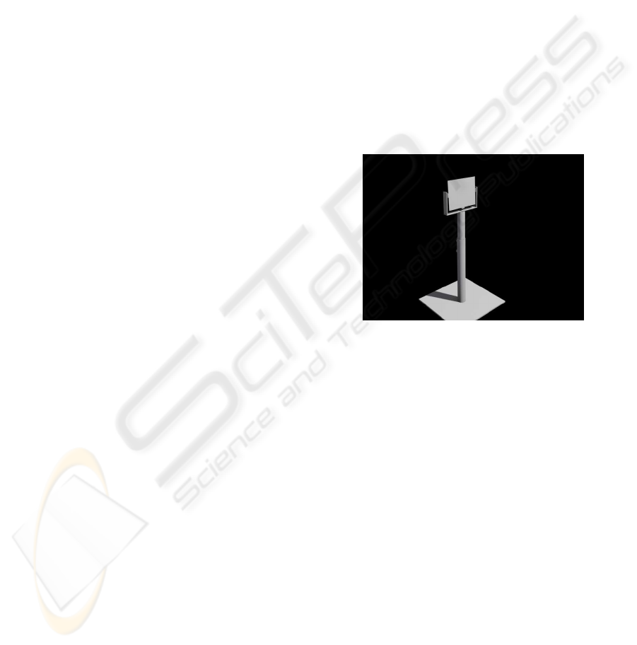
This means that the monitor stands on a pole, the user
can pan and tilt the monitor, and since the video cam-
era is mounted behind the monitor the user can ef-
fectively point the camera in any direction. Figure 1
shows a 3D model of the proposed system.
The video camera approximately rotates around
the optical center of the lens. High precision, high
speed optical encoders (rotations measured with an
accuracy of 1/200th degree) are used to continuously
inform the system about the viewing direction of the
camera).
In the present setup the monitor is a 42 inch
plasma TV. The video camera is a Point Grey Drag-
onfly2 1024x768 color camera connected to the com-
puter with an IEEE 1394 FireWire connection. The
camera gives 30 frames per second in Bayer color
coding pattern (since it is not possible to transmit
full resolution RGB images at 30 fps over FireWire).
The computer is a single processor 2.2 GHz AMD
athlon 64 machine with 3 GByte RAM. The com-
puter is running 32 bit Windows XP (emulating 32
bit). The graphics card is an NVIDIA GeForce 6800
series card. The optical encoders are two Heidenhain
ROD 480 connected to a Heidenhain IK220 PCI slot
interface card in the computer.
The system is implemented in C++ using the Di-
rect3D graphics API. All geometry is loaded into the
system in .x format exported from 3DStudioMax. The
system can handle animations in the form of procedu-
ral rigid body transformations (translation, rotation,
scaling), which are configured with a simple scripting
language.
Figure 1: 3D model of the proposed system. The actual pole
with mounting bracket for panning and tilting the monitor
is not yet constructed. Presently, the monitor is static and
only the camera is mounted in a pan-tilt rig.
2.2 Assumptions
The developed techniques in the present system rest
on a number of assumptions the validity of which is
discussed further in section 5.
The present version of the system assumes the il-
lumination conditions in the real scene to be static. In
fact, a High Dynamic Range (HDR) omni-directional
environment map of the real location is captured as
part of an off-line process while setting up the system
at a given location. This environment map is used
for all rendering of virtual geometry in the scene, and
therefore the system would not respond visually cor-
rect if drastic changes in the illumination conditions
occurred. In locations with purely artificial light it
is easy to ensure that the illumination conditions do
not change. In locations with substantial outdoor il-
lumination the passing of time and changes in cloud
conditions affect illumination conditions, but our ex-
perience with demonstrating the system to hundreds
A SCALABLE GPU-BASED APPROACH TO SHADING AND SHADOWING FOR PHOTOREALISTIC REAL-TIME
AUGMENTED REALITY
253
of people shows that people do not notice that the vir-
tual illumination is slightly inconsistent with the real
illumination, as long as it is merely qualitatively con-
sistent.
The environment map approach additionally as-
sumes that the real scene is distant relative to the vir-
tual geometry, or at least that the environment map is
acquired from a position which is quite close to where
virtual objects will be placed. If the scene is not dis-
tant the environment map acquired at one position is
not valid at other locations, for example 5 or 10 me-
ters away for indoor scenes. In outdoor scenes the
assumption that the real scene is distant is typically
more valid.
It is furthermore assumed that the video camera is
internally calibrated (focal length, image center and
lens distortion). This calibration is also performed
during system setup and therefore no changes can be
made to lens zoom or aperture (iris opening) while the
system is in operation.
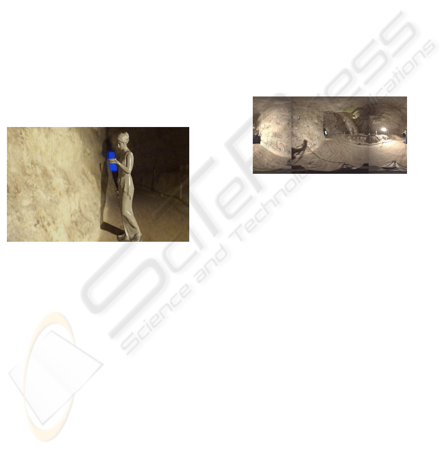
Figure 2: System operating in abandoned chalk mine
demonstrating virtual shadows cast on rough rock wall. The
rock wall is modelled as high resolution mesh with posi-
tional noise added in the normal direction, such that the vir-
tual shadow falls across the rock wall in a credible manner.
Our approach assumes that a 3D model of parts
of the real scene is available. This 3D model is used
for handling occlusion between real and virtual ge-
ometry, for casting virtual object shadows on the real
scene, and vice versa. In many cases the real scene 3D
geometry can be quite rough. Figure 2 shows a screen
shot from the system operating in an abandoned chalk
mine during a recent digital art festival. Finally, our
approach to rendering virtual shadows cast on the real
elements in the scene is only physically valid pro-
vided the shadow receiving real scene surfaces can be
considered as diffuse reflectors.
2.3 Hdr Environment Map
To enable shading of virtual objects in manner which
is consistent with the illumination conditions in the
real scene an illumination model of the real scene
is required. For this work an image-based model
has been adopted similar to e.g., (Barsi et al., 2005;
Havran et al., 2005; Gibson et al., 2003; Debevec,
2002; Debevec, 1998; Kanbara and Yokoya, 2004).
Typically a High Dynamic Range (HDR) omni-
directional image (environment map) of the real scene
is acquired by fusing images taken at multiple expo-
sures of a polished steel/chrome sphere, (Debevec and
Malik, 1997). In the present work environment maps
are acquired with a Canon EOS 1Ds Mark II 16 Mega
pixel digital SLR camera fitted with a Sigma 8mm
180 degree field-of-view fish eye lens. This setup en-
ables us to acquire a complete hemi-sphere in each
exposure. Camera response curve calibration, HDR
fusion, and hemisphere fusion is done with the HDR-
Shop 2.0 software, (Debevec et al., 2006). Figure 3
shows such a finished environment map.
Figure 3: Longitude-latitude HDR environment map of
chalk mine constructed from two hemispherical exposure
sets. Due to slight lens vignetting the seams between the
two hemispheres are visible as darkened vertical lines in
the long-lat mapping. Tripod and photographer shadow arti-
facts are also visible. Such artifacts do not influence virtual
object rendering noticeably. The dynamic range between
the lamp and the floor is approximately 10000:1.
2.4 Shading and Shadowing
All shading of virtual geometry is performed in HDR,
i.e., in floating point values and the last step in render-
ing to the framebuffer is a tonemapping to 8 bit RGB
values (Low Dynamic Range, LDR).
The rendering of virtual geometry in the proposed
system is an additive mixture of diffuse reflection and
reflection mapping. Figure 4 shows a closeup of an
object with a such a mixture. The scripting language
mentioned above also controls which virtual geom-
etry is loaded and what material parameters to ap-
ply when rendering the objects. This way the dif-
fuse reflection coefficient, the diffuse albedo and the
specular reflection coefficient can be specified. At
present texture mapping and glossy reflection is not
supported.
Based on the environment map acquired in ad-
vance the irradiance map (total irradiance for all pos-
sible surface normals) is computed and used in con-
GRAPP 2007 - International Conference on Computer Graphics Theory and Applications
254
junction with the diffuse reflection coefficient and the
diffuse albedo to give the diffuse reflection contribu-
tion. Basing the diffuse shading on the environment
map allows the system to correctly reproduce global
illumination effects such as color bleeding from the
environment to the virtual objects.
The reflection component is achieved with stan-
dard reflection mapping, i.e., by computing the re-
flection direction and looking up in the environment
map to fetch incoming radiance from that particular
direction. The reflection component is scaled by the
specular reflection coefficient.
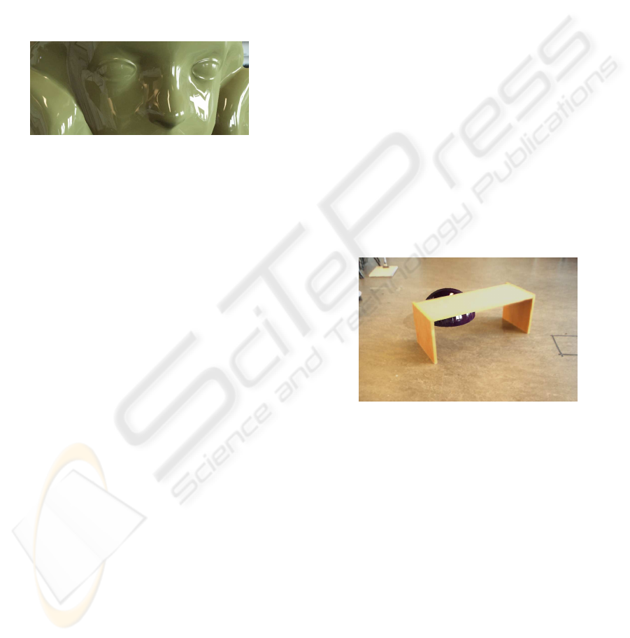
Figure 4: Close-up of virtual sculpture rendered with our
system. A mixture of diffuse reflection and reflection map-
ping, both based on the environment map is used for ren-
dering of virtual objects. The reflection mapping contribu-
tion helps give objects a nice shiny appearance. In a post-
processing step random image noise is added to the ren-
dered virtual geometry to mimic the slight image noise ap-
parent in the feed from the video camera used to film the
real scene.
The handling of shadows represents the core of
the contributions of this work. The HDR environment
map is approximated by a number, N, of point light
sources using techniques which will be described in
section 3.2. These sources are sorted in descending
order according to their intensity, and the strongest M
sources will subsequently be allowed to cast shadows.
The remaining N − M sources contribute to shading
but are considered too weak to cast shadows. This is
where the scalability of the proposed approach comes
in: in principle all sources should cast shadows of
varying depths according to their individual radiant
power, but it is too costly for contemporary graphics
hardware to render shadows from so many sources, so
by only casting shadows from the strongest M sources
we can to chose M so as to balance resulting framerate
and visual quality.
Section 3.6 describes the proposed pixel shader
which renders shadows into the final image on both
real and virtual geometry. The shader essentially
computes an overlay which is multiplied to the image
on a per pixel basis, and which results in appropriate
attenuation in shadowed areas. The shader handles
the double shadow problem described in section 1.2.
3 APPLIED TECHNIQUES
The previous section gave a broad view of the steps
involved in the proposed Augmented Reality render-
ing process. Subsequently a more technical descrip-
tion is provided. First we describe the two main ele-
ments of the off-line phase: 1) calibration of the setup,
and 2) the HDR environment map capture process.
3.1 Calibration of Video Camera and
Pan-Tilt Rig
To render virtual objects which are embedded cor-
rectly in the real scene it is necessary to have com-
plete knowledge of the mapping from world coordi-
nates to image coordinates of the video signal. This
requires knowledge of 1) the internal parameters of
the video camera, 2) the transformation from world
to pan-tilt unit coordinates, and 3) the transformation
from pan-tilt unit coordinates to camera coordinates.
The proposed system incorporates interactive calibra-
tion steps to acquire this information during a system
setup phase. Figure 5 shows how the system can be
calibrated to a world model to handle occlusion be-
tween real and virtual geometry.
Figure 5: Screen dump from system illustrating virtual
sphere being occluded by real table. This requires calibra-
tion of the complete transformation from world to image
coordinates and a 3D model of the occluder.
The internal parameters (focal length, pixel aspect
ratio, image center and lens distortion) are calibrated
from multiple images of a checker board pattern us-
ing the OpenCV computer vision library, (Source-
Forge.net, 2006). Then a cross hair sight is rendered
at the image center and the user then rotates the cam-
era so as to point the cross hair to a number (at least
4) of fixpoints manually identified in the geometric
model of the real environment (real geometry). By
recording encoder readings for each fixpoint sighting
it is possible to calibrate the position and orientation
of the pan-tilt unit relative to the world coordinate
system. This calibration is performed by an iterative
optimization process we developed for this particular
purpose, but which is not described in this paper.
A SCALABLE GPU-BASED APPROACH TO SHADING AND SHADOWING FOR PHOTOREALISTIC REAL-TIME
AUGMENTED REALITY
255

Finally, by freezing an image from the video
stream and identifying (with the mouse cursor) a
number of fixpoints (at least 4) we can calibrate the
position and orientation of the camera relative to
the world coordinate system for that particular im-
age. This calibration step is also accomplished with
the OpenCV library. Multiplying the pan-tilt unit to
world transformation with the world to camera trans-
formation then gives us the pan-tilt unit to camera
transformation.
Once these calibration steps are completed the
real-time mapping from world to image coordinates
is completely controlled by the encoder readings.
3.2 Capturing the Illumination
Conditions
As described previously a HDR environment map is
the central representation of the real scene illumina-
tion conditions in the system. The environment map
is captured as a part of setting up the system. First
we formulate how the concept of irradiance relates to
discrete environment maps.
The environment map is a spatially discrete mea-
surement of the continuous function describing the in-
cident radiance (measured in W/(m
2
· Sr)), which in
turn is a function of the incident direction. Let ~n be
the normal of a differential area surface, and let Ω
~n
be
the hemi-sphere defined by this normal. By integrat-
ing the incident radiance, L(
~
ω), from the direction
~
ω
over the hemi-sphere the total irradiance, E(~n), can
be computed.
In standard spherical coordinates a di-
rection in space is written as
~
ω(θ,φ) =
[sin(θ)cos(φ),sin(θ)sin(φ),cos(θ)], where θ is
the angle the direction vector makes with the coordi-
nate system z-axis (latitude), and φ is the angle the
projection of the vector on the xy-plane makes with
the x-axis, (longitude).
In this paper we will exclusively use the latitude-
longitude mapping (LL mapping) of environment
maps. Let the resolution of the LL environment map
be W by H pixels, and let u and v represent pixel
coordinates in an image coordinate system with ori-
gin in the top left corner of the LL map, and v-
axis oriented downwards. Thus the top row corre-
sponds to θ = 0 and the bottom row corresponds to
θ = π. Moreover φ = 0 corresponds to the leftmost
column. Each environment map pixel, P(u, v), repre-
sents the radiance in W/(m
2
· Sr) (if the map acquisi-
tion is radiometrically calibrated) from the direction
given by
~
ω(u,v) =
~
ω(θ(v),φ(u)), where θ(v) = v∆
θ
and φ(u) = u∆
φ
, where ∆
θ
= π/H and ∆
φ
= 2π/W.
The discrete version of the total irradiance, E(~n), for
a given normal~n then becomes:
E(~n) ≈
∑
u
∑
v
P(u,v)(~n·
~
ω(u,v))sin(θ(v))∆
θ
∆
φ
(1)
where summations are subject to the constraint that
(θ(v),φ(u)) ∈ Ω
~n
, i.e., that the combinations of u and
v represent pixels inside the region corresponding to
the hemi-sphere defined by the surface normal~n.
From Eq. 1 it is evident that if every pixel, P(u, v),
in the LL map is scaled with ∆
θ
· ∆
φ
= 2π
2
/(W · H)
and weighted by sin(θ(v)), we get a very simple
summation. We therefore produce a new LL map,
where each pixel Q(u,v) = 2π
2
P(u,v)sin(θ(v))/(W ·
H). The irradiance for a given normal is then simply
computed as:
E(~n) ≈
∑
u
∑
v
Q(u,v)(~n·
~
ω(u,v)) (2)
where the summations again are subject to the con-
straint that (θ(v),φ(u)) ∈ Ω
~n
.
To recapitulate in a different way: Each pixel in
the LL map acts as a small area light source subtend-
ing a solid angle of A
p
= 2π
2
/(W · H) [Sr/pixel]. By
weighting each pixel by sin(θ(v)) we achieve ”per-
mission” to treat all pixels equally in the sense that
we cancel out the effect of the non-uniform sampling
density of the LL mapping (poles are severely over-
sampled). By subsequently scaling by A
p
we convert
the solid angle domain from steradians to pixels. I.e.,
each Q(u,v) = 2π
2
P(u,v)sin(θ(v))/(W · H) measures
the radiance in W/(m
2
· pixel), such that by perform-
ing a simple cosine weighted sum of pixels we di-
rectly get the irradiance contributed by the pixels in-
volved in the sum (Eq. 2). Another way of putting
it is: each pixel Q(u, v) is an area light source con-
tributing Q(u,v)(~n ·
~
ω(u,v)) irradiance to the differ-
ential area surface with normal~n.
Several techniques exist for approximating an en-
vironment map with a limited number of light sources
to reduce the computational cost associated with
Image-Based Lighting, (Debevec, 2005; Barsi et al.,
2005; Havran et al., 2005; Cohen and Debevec, 2001;
Madsen et al., 2003). For this work the Median Cut
technique described in (Debevec, 2005) has been cho-
sen. The technique recursively splits the environment
map along the longest dimension into regions of ap-
proximately equal summed radiance. The techniques
splits all regions K times, resulting in either 2, 4, 8,
16, 32 etc. regions. Each resulting region is finally
replaced with a single light source at the centroid, and
the radiance of that source is set to the sum of all the
pixel values in the region. Figure 6 shows the result of
applying the Median Cut technique to an environment
map.
We apply the Median Cut algorithm to the Q(u,v)
map to produce N sources (on the order of 16 to 128),
GRAPP 2007 - International Conference on Computer Graphics Theory and Applications
256

Figure 6: Regions and sources resulting from running the
Median Cut approximation algorithm to a depth of 5, i.e., to
32 regions.
then we sort them according to power and pick the M
strongest, which in the real-time steps of the system
will be treated as separate point sources contributing
with irradiance and will be involved in casting shad-
ows using the shadow map technique. The remaining
N − M sources are integrated with cosine weighting
into a combined irradiance for each of all possible
normal directions in an LL irradiance map. The in-
tention with this irradiance map is to capture the ”am-
bient” illumination in the scene, but it still depends
on normal directions and is thus much more realistic
than a standard Phong ambient term. During subse-
quent rendering the ”ambient” irradiance for a given
normal direction is then found by a simple look-up
into the irradiance map.
Let ℜ
i
be the ith region, and let (u
i
,v
i
) be the
centroid of the ith region. Furthermore, let L
i
be the
summed radiance within region ℜ
i
:
L
i
=
∑
ℜ
i
Q(u,v) (3)
The ”ambient” irradiance map, E
a
(u,v), is then com-
puted in some resolution, e.g., W by H, by integrating
cosine weighted contributions from each of the N− M
weakest sources:
E
a
(u,v) =
N−M
∑
i=1
L
i
· (~n(u,v) ·
~
ω(u
i
,v
i
)) (4)
For a given normal, ~n, the ambient irradiance,
E
a
(~n), is then found by look-up in the E
a
(u,v) map.
3.3 The On-Line Rendering Process
Having thus described the steps involved in prepar-
ing for running the system we now turn toward de-
scribing the actual real-time rendering process. In
pseudo-code the process may be described as follows:
while(1)
1. grab video image and get optical encoder readings
2. demosaic Bayer video image to full RGB, rectify
image and expand to HDR texture
3. render real geometry to depth buffer (for subse-
quent occlusion handling between real and virtual
geometry)
4. render virtual geometry to the HDR texture from
step 2 applying depth check with depth buffer
from step 3, and using a shader which computes
diffuse and specular reflection
5. render real geometry to R channel of each of the
M spotlight depth textures
6. render virtual geometry to G channel of each of
the M spotlight depth textures
7. render virtual and real geometry to the HDR tex-
ture, this time with a shader which computes how
much each fragment must be attenuated to take
shadows from the M sources into account
8. render post-processing effects (e.g., additive im-
age noise)
9. render quad to framebuffer with a shader that
tonemaps the HDR texture to LDR
do
We subsequently provide further explanation on
each of these steps.
3.4 Processing Video Images
The implemented application runs in two threads: one
for rendering and one for getting encoder readings.
Time stamps from the video image grabbing process
are used to synchronize encoder readings to images.
As explained in section 2.1 images are grabbed in
Bayer pattern format and the uploaded to the graphics
card as a texture. A full screen quad with this texture
is the rendered to another texture using a pixel shader
which demosaics Bayer pattern to full RGB and rec-
tifies the image by correcting for the lens distortion
using the distortion parameters from the internal cal-
ibration. Finally a full screen quad textured with the
demosaiced and rectified video image is rendered to a
High Dynamic Range (HDR) texture in order to ex-
pand the 8 bit per channel video image to floating
point values, because the rest of the rendering process
is carried out in HDR.
3.5 Rendering Virtual Geometry
The next step is to render the virtual (augmented) ge-
ometry into the HDR texture containing the processed
video image. As described in section 2.4 virtual ge-
ometry is rendered with a mixture of diffuse shad-
ing and reflection mapping. The reflected radiance
from a fragment, L( f ), of the virtual geometry is con-
trolled by the diffuse (K
d
) and specular (K
s
) reflec-
tion coefficients, respectively. Let ~n( f ) and ~p( f) be
the normal and the position of the fragment, and let
~
l
i
be the direction vector from the fragment to the ith
A SCALABLE GPU-BASED APPROACH TO SHADING AND SHADOWING FOR PHOTOREALISTIC REAL-TIME
AUGMENTED REALITY
257

light source. The fragment’s radiance can then be ex-
pressed as:
L( f) = K
d
E
a
(~n( f)) +
N
∑
i=N−M+1
L
i
· (~n( f) ·
~
l
i
)
!
+
K
s
· Q(u(~r( f)), v(~r( f))) (5)
expressing the fact that total irradiance at the fragment
is the sum of the ambient irradiance (from a look-up
in the E
a
map) and the combined irradiance contribu-
tion from the M most powerfull sources. The reflec-
tion vector~r( f) for the fragment is used for a look-up
into the environment map to compute the reflection
mapping radiance contribution.
The virtual geometry is rendered into the HDR
texture using a pixel shader which implements the
shading function in eq. 5. As described in step 3 in
section 3.3 the real geometry has previously been ren-
dered into the z-buffer so that when rendering virtual
geometry occlusions can be handled correctly (as il-
lustrated in figure 5).
3.6 Handling Shadows
The HDR texture now contains the processed video
image and the rendered virtual geometry. Naturally
the video image contains shadows from real geometry
onto real geometry, but no shadows involving virtual
geometry, neither as occluder nor as receiver.
In this work the shadow map algorithm has been
used as the basic technique in detecting shadows,
(Watt and Policarpo, 2001). Basically the algorithm
involves first rendering the depth values of the scene
from the viewpoint of the light source into a shadow
map. Then the scene is rendered from the normal
viewpoint and the for each fragment the fragment po-
sition is transformed to the light source coordinate
system and the distance to the transformed point is
checked against the stored depth value in the shadow
map. If the depth of the fragment is larger than what is
stored in the shadow map the fragment is in shadow.
The proposed system operates with M shadow
casting sources. These sources were found from the
environment map and therefore only have direction
vectors. We place the sources at a distance which is
suitable given the size of the scene. Alternatively,
source directions can be intersected with a coarse
3D model of the environment to get a more accurate
source placement. We then render the real geometry
to the R channel of each of the M shadow maps, and
the virtual geometry to the G channels.
Using the R and G channels for real and virtual
geometry respectively allows the shadow shader pro-
gram to distinguish between shadows cast by real and
virtual geometry. Subsequently we will use a notation
where RS
i
( f) is a Boolean which is true if no real ge-
ometry casts shadow on the fragment f given the ith
source. Similarly VS
i
( f) is true if no virtual geome-
try occludes the fragment’s ”view” of the ith source.
Our approach to shadows is based on thinking in
terms of shadows being the absence of irradiance. Let
E
R
( f) denote the irradiance on a fragment (real as
well as virtual) which only takes into account shad-
ows cast by real objects:
E
R
( f) = E
a
(~n( f)) +
N
∑
i=N−M+1
RS
i
( f) · L
i
· (~n( f) ·
~
l
i
) (6)
Now, at this point in the rendering chain every-
thing in the HDR texture is only subjected to shadows
from real geometry, namely shadows in the real scene
as captured by the video camera. So if the HDR tex-
ture is divided by the E
R
( f) irradiance for every pixel
the result would be the diffuse albedo of the fragment,
since radiance equals the product of albedo and irra-
diance for diffuse surfaces. This in effect corresponds
to taking the shadows away from the original image.
If we then multiply the albedos with a per frag-
ment irradiance, E
R+V
( f), which takes into account
both real and virtual geometry for casting shadows,
we would get the correct radiances where virtual ge-
ometry also casts shadows.
E
R+V
( f) = E
a
(~n( f)) +
N
∑
i=N−M+1
RS
i
( f) · VS
i
( f) · L
i
· (~n( f) ·
~
l
i
) (7)
In practice we do the following. We set alpha
blending mode to modulation (multiplication), and
then render real and virtual geometry into the HDR
texture with a pixel shader which returns the irradi-
ance fraction E
R+V
( f)/E
R
( f). Due to the modulation
blending this ratio is multiplied with the pixel values
(radiances) in the HDR texture. In this way we in one
step compute the diffuse albedos of the entire scene
and then re-light the whole scene with illumination
taking shadows from both real and virtual geometry
into account.
For most real scenarios it will be impossible to ac-
curately model all real geometry, and in most of our
examples will only have a few essential objects and a
ground plane modelled. The irradiance fraction multi-
plication will degenerate to a multiplication with 1 in
all image areas (all fragments) where virtual objects
do not cast shadows. Therefore it is not necessary to
3D model real geometry apart from potential virtual
geometry shadow receiving surfaces.
The presented AR shadow pixel shader is physi-
cally correct when shadow receiving surfaces can be
GRAPP 2007 - International Conference on Computer Graphics Theory and Applications
258
characterized as diffuse reflectors. This is naturally
not generally the case in real scenes, but in our expe-
rience the error made is rarely actually noticeable.
The next step in the rendering pipeline is to ren-
der post-processing effects such as simulated camera
noise on virtual geometry. A fixed noise texture has
been generated off-line and is mapped on a full-screen
quad. This quad is then rendered to the HDR texture
in additive blending mode. To avoid the noise overlay
appearing completely static a random offset is added
to the texture coordinates per cycle, and texture ad-
dressing is set to wrap. Rendering of the noise quad
is masked by a stencilbuffer set up by a render pass
of virtual geometry so only virtual geometry receives
simulated camera noise.
Finally a full-screen quad mapped with the HDR
texture is rendered to the framebuffer with a pixel
shader which transforms HDR fragment radiance,
L( f), to an LDR brightness value as brightness =
1− exp(−γ· L( f)), where γ is an adjustable exposure
value. There are may more advanced tone mapping
operators, but we have not made an important issue of
this since the available video stream of the real scene
is inherently LDR.
4 EXPERIMENTAL RESULTS
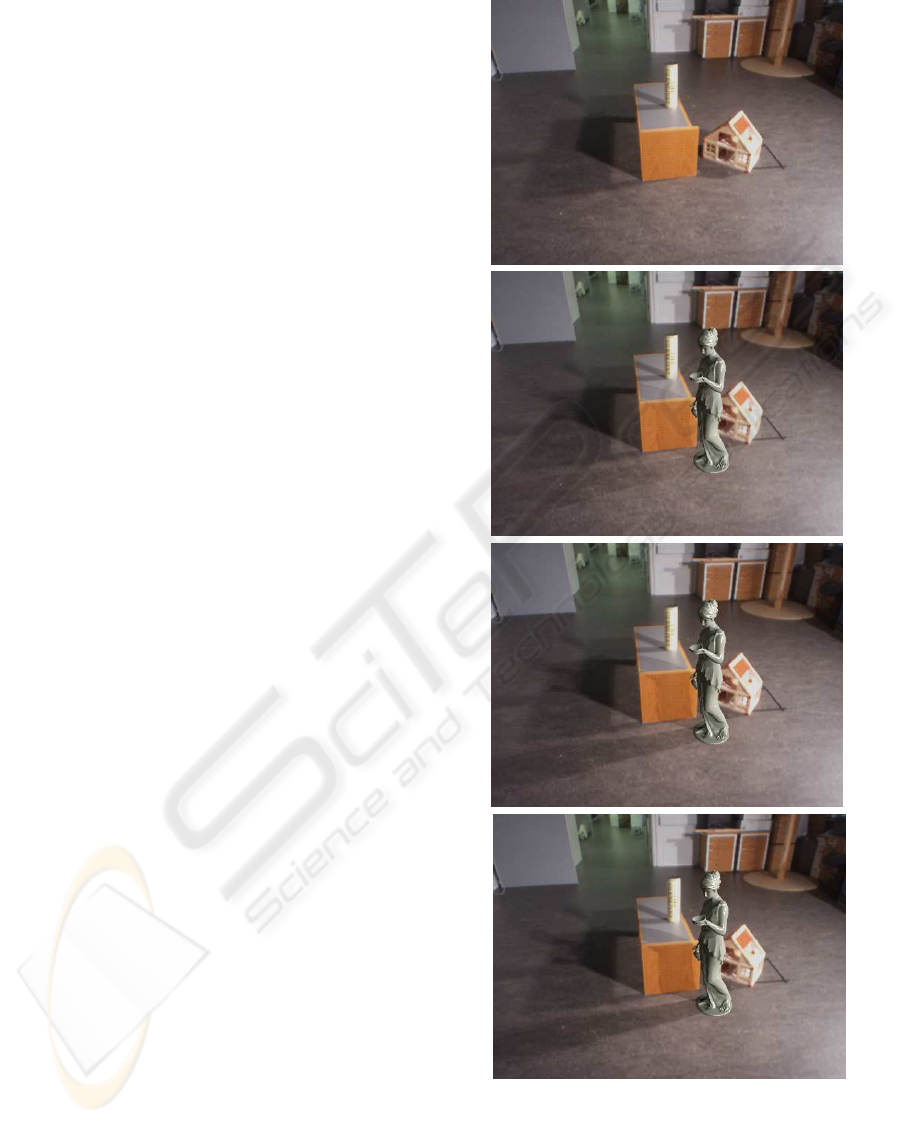
Figure 7 demonstrates shadows cast by virtual geom-
etry on to real geometry, and also demonstrates that
shadows cast by virtual objects do not interfere with
real shadows in areas were real geometry has already
created shadows in the video image, i.e., no double
shadow artifacts are present. The illumination in the
scene is dominated by two lamps (500 W light bulb
with 40 cm aluminium reflector) which at this dis-
tance subtend sufficient solid angle to create clear soft
shadows.
There are several important topics to discuss in
relation to the figure: 1) the scalability of the ap-
proach, 2) the shadow mixing performance, and 3)
the real-time albedo computation performed to render
the depth of virtual shadows correctly.
As seen in figure 7 the proposed approach is in
fact scalable in the sense that it offers a direct way of
balancing computational load and visual accuracy. In
the case of rendering with 4 sources for shadow cast-
ing (M = 4) the resulting virtual shadows are a little
crude, with hard shadow edges clearly showing, es-
pecially for the shadow near the bottom of the image.
Furthermore, the depth of the shadows are not cor-
rect. This problem is due to the fact that when M is
very small some directional sources which are actu-
ally placed on the lamp reflector are not included in
Figure 7: Screenshots demonstrating ability to mix multi-
ple shadows and handle the double shadow problem. The
top image is the scene without any augmentation. The next
three images downwards show rendering with 4, 10, and 15
shadow casting sources, respectively. The 10 sources case
is running at 15 frames per second when shadow maps are
rendered at 1024x1024 resolution.
A SCALABLE GPU-BASED APPROACH TO SHADING AND SHADOWING FOR PHOTOREALISTIC REAL-TIME
AUGMENTED REALITY
259

the M most powerfull, and therefore some lamp irra-
diance is not accounted for, resulting in shadows not
being dark enough. In our implementation the max-
imum value for M is 15 (limited by the number of
texture samplers for shadow maps that can be associ-
ated with a fragment shader). For M = 15 the visual
quality of virtual shadows in terms of depth and edge
softness is quite close to the real shadows.
In the demonstrated case the real and virtual shad-
ows mix well, in the sense that the transition from a
real shadow to a virtual one is quite seemless. An ex-
ample is the virtual shadow cast by the statue extend-
ing (to left) past the real shadow of the table from first
one lamp (deep shadow since no lamp shines directly
here), and then the other lamp (lighter shadows since
one lamp shines here). This clearly demonstrates the
ability of our approach to handle the double shadow
problem. Yet, such performance is only possible with
accurate 3D models of the relevant elements in the
real scene (in this case the table). In section 5 pro-
vides a little more discussion on this issue.
As described in section 3.6 virtual shadows are ac-
tually rendered with a re-lighting approach, where we
in one step on a per-pixel basis compute the diffuse
albedo of the surface and re-light it with the irradi-
ance taking into account the flux being occluded by
the virtual object. Since the approach rests on a num-
ber of assumptions the computed albedos can be in-
correct to some degree. To name some sources of
error: the surface may not be perfectly diffuse, the
environment map approach forces all sources to be di-
rectional so varying surface to source distance is not
handled correctly, and some of the irradiance (repre-
sented by the N − M weakest sources) is not subject
to visibility/shadow computations. The reason these
arifact do not show more clearly is that the re-lighting
is performed with the same errors, so the irradiance
fraction is unity for all areas which are not influenced
by a virtual object shadow. Nevertheless, the long
shadow cast in the bottom of figure 7 for M = 15
shows that depth and color tone are very consistent
with real shadows in the scene, indicating that the
albedo computation is accurate enough for this pur-
pose, though perhaps not accurate enough for inverse
rendering systems.
5 FUTURE WORK
Section 2.2 stated some assumptions that the pre-
sented techniques are based on. Several of these as-
sumptions are worth further discussion. Here only the
ones where we have ideas for future work will be con-
sidered.
First of all the present system is heavily based
on having a HDR environment map acquired in ad-
vance leading to an assumption that illumination in
the scene is static. The work presented in (Havran
et al., 2005) is centered around a HDR video camera
enabling live capture of environment maps in HDR.
Our approach would work straight forward with such
a camera for continuously capturing the illumination
environment. Alternatively, for outdoor scenes, re-
cent work has demonstrated a way to alleviate static
illumination assumption, (Jensen et al., 2006b; Jensen
et al., 2006a). This work present an approach to
real-time estimation of outdoor illumination condi-
tions from LDR video by continuously estimating the
amount of sun and sky illumination based on reflected
radiances from surfaces in the scene, i.e., using the
scene as its own light probe. Furthermore, for indoor
scenes, we are investigating ways of continuously up-
dating the environment map with images from the
video camera as it is being pointed in various direc-
tions by the user. To enable run-time HDR acquisition
it will be necessary to adjust video camera exposure
settings, e.g., by letting every 10th frame by acquired
with very low light sensitivity (and not showing this
frame to the user).
Using environment maps force an assumption that
the real scene is distant, but given a rough 3D model
of the scene light source directions can be intersected
with the real scene geometry to get proper 3D place-
ment for point sources. In this case illumination could
be based on an irradiance volume, (Greger et al.,
1998), in order to make illumination dependent on po-
sition in space.
The double shadow problem has in this work been
solved by assuming that the relevant real geometry
has been accurately modelled. In a general scenario
this will never be possible, e.g., when there are people
and vegetation in the scene. In a not too distant future
high speed high resolution laser range finder cameras
will enable real-time scene depth capture, but we are
currently investigating techniques for classifying pix-
els as shadow based entirely on the video image infor-
mation. (Jacobs et al., 2005) have presented promis-
ing results in this direction and shadow segmentation
methods are currently the focus of much research.
6 CONCLUSION
We have presented a complete AR system capable of
shading virtual objects and render shadows in a way
which is consistent with the illumination in the real
scene.
Our approach allows for scaling the visual quality
GRAPP 2007 - International Conference on Computer Graphics Theory and Applications
260

with the increasing performance of graphics hardware
in the sense that as hardware improves more and more
light sources can be included in the set of sources
which are allowed to cast shadows.
Another important element is the proposed tech-
nique to handling the actual shadowing by essentially
computing albedos and relighting the scene with ir-
radiance which takes both virtual and real geometry
into account when shading shadow areas. In this a
physically-based approach is obtained which will pro-
vide correct intensities and color balances in shadow
areas.
REFERENCES
Barsi, A., Szirmay-Kalos, L., and Sz
´
ecsi, L. (2005). Im-
age/based illumination on the gpu. Machine Graphics
and Vision, 14(2):159 – 169.
Cohen, J. M. and Debevec, P. (2001). The Light-
Gen HDRShop plugin. www.hdrshop.com/main-
pages/plugins.html.
Debevec, P. (1998). Rendering synthetic objects into real
scenes: Bridging traditional and image-based graph-
ics with global illumination and high dynamic range
photography. In Proceedings: SIGGRAPH 1998, Or-
lando, Florida, USA.
Debevec, P. (2002). Tutorial: Image-based lighting. IEEE
Computer Graphics and Applications, pages 26 – 34.
Debevec, P. (2005). A median cut algorithm for light probe
sampling. In Proceedings: SIGGRAPH 2005, Los An-
geles, California, USA. Poster abstract.
Debevec, P. and Malik, J. (1997). Recovering high dynamic
range radiance maps from photographs. In Proceed-
ings: SIGGRAPH 1997, Los Angeles, CA, USA.
Debevec et al., P. (2006). www.hdrshop.com.
Gibson, S., Cook, J., Howard, T., and Hubbold, R. (2003).
Rapic shadow generation in real-world lighting envi-
ronments. In Proceedings: EuroGraphics Symposium
on Rendering, Leuwen, Belgium.
Greger, G., Shirley, P., Hubbard, P. M., and Greenberg,
D. P. (1998). The irradiance volume. IEEE Computer
Graphics and Applications, 18(2):32–43.
Havran, V., Smyk, M., Krawczyk, G., Myszkowski, K., and
Seidel, H.-P. (2005). Importance Sampling for Video
Environment Maps. In Bala, K. and Dutr
´
e, P., editors,
Eurographics Symposium on Rendering 2005, pages
31–42,311, Konstanz, Germany. ACM SIGGRAPH.
Jacobs, K., Angus, C., and Loscos, C. (2005). Automatic
generation of consistent shadows for augmented real-
ity. In Proceedings: Graphics Interface, Vancouver,
Canada.
Jensen, T., Andersen, M., and Madsen, C. B. (2006a). Es-
timation of dynamic light changes in outdoor scenes
without the use of calibration objects. In Proceed-
ings: International Conference on Pattern Recogni-
tion, Hong Kong, page (4 pages).
Jensen, T., Andersen, M., and Madsen, C. B. (2006b). Real-
time image-based lighting for outdoor augmented re-
ality under dynamically changing illumination condi-
tions. In Proceedings: International Conference on
Graphics Theory and Applications, Set
´
ubal, Portugal,
pages 364–371.
Kanbara, M. and Yokoya, N. (2004). Real-time estima-
tion of light source environment for photorealistic
augmented reality. In Proceedings of the 17th In-
ternational Conference on Pattern Recognition, Cam-
bridge, United Kingdom, pages 911–914.
Loscos, C., Drettakis, G., and Robert, L. (2000). Interative
virtual relighting of real scenes. IEEE Transactions
on Visualization and Computer Graphics, 6(4):289 –
305.
Madsen, C. B., Sørensen, M. K. D., and Vittrup, M. (2003).
Estimating positions and radiances of a small number
of light sources for real-time image-based lighting. In
Proceedings: Annual Conference of the European As-
sociation for Computer Graphics, EUROGRAPHICS
2003, Granada, Spain, pages 37 – 44.
Sato, I., Sato, Y., and Ikeuchi, K. (1999a). Acquiring a radi-
ance distribution to superimpose virtual objects onto
a real scene. IEEE Transactions on Visualization and
Computer Graphics, 5(1):1–12.
Sato, I., Sato, Y., and Ikeuchi, K. (1999b). Illumination dis-
tribution from brightness in shadows: adaptive esti-
mation of illumination distribution with unknown re-
flectance properties in shadow regions. In Proceed-
ings: International Conference on Computer Vision,
pages 875–882.
SourceForge.net (2006). OpenCV Computer Vision Library,
www.sourceforge.net/projects/opencv/.
Watt, A. and Policarpo, F. (2001). 3D Games: Real-
Time Rendering and Software Technology, volume 1.
Addison-Wesley.
A SCALABLE GPU-BASED APPROACH TO SHADING AND SHADOWING FOR PHOTOREALISTIC REAL-TIME
AUGMENTED REALITY
261
