
EFFICIENT DIGITAL FREQUENCY DOWN CONVERTER
STRUCTURE USING CIC FILTERS AND INTERPOLATED
FOURTH-ORDER POLYNOMIALS
Youngbeom Jang, Do-Han Kim
Sangmyung University, San 98-20, Anseo-dong, Cheonan-Si, Chungnam-Do, Korea
Won-Sang Lee
TamulMultimedia, Anyang Trade Center, Bisan-dong, Anyang-Si, Gyeonggi-Do, Korea
Keywords: DFDC, CIC, ISOP, IFOP.
Abstract: In this paper, we propose an efficient digital frequency down converter (DFDC) structure using CIC
(Cascaded Integrator-Comb) decimation filters and interpolated fourth-order polynomials (IFOP). Typical
DFDC with high decimation factors consist of a CIC filter and a halfband filter. By inserting the proposed
IFOP between the CIC and halfband filters, it is shown that passband droop and aliasing band attenuation
characteristics are simultaneously improved. Since the IFOP requires only three multiplications, the
proposed DFDC can be used in intermediate frequency blocks of the high-speed communication systems.
1 INTRODUCTION
Since DFDCs (Digital Frequency Down Converters)
with narrow bandwidth require high orders, power
consumption and implementation area should be
considered. To save on implementation cost,
conventional VLSI chips for DFDCs utilize CIC
filters followed by halfband filters and a
Programmable Finite Impulse Response (PFIR) filter.
For example, a DFDC chip with a 16384 decimation
ratio consists of CIC, halfband, and PFIR stages,
where the decimation factors of the CIC, halfband
and PFIR stages are 32, 32 and 16, respectively. CIC
filters are widely used in the first stage of the DFDC
since they do not require multiplications(Hogenauer,
1981). Studies to improve CIC filter characteristics
have been undertaken(Yang, 1996)(Gao, 1999). In
(Kwentus, 1997), a sharpening technique using a
combination of three filters(Kaiser, 1977) is applied
to a CIC filter. By using this method, the ripple in
the passband and attenuation in the aliasing band can
be mitigated, but the implementation cost is quite
high. In (Oh, 1999), ISOP(Interpolated Second
Order Polynomial) is inserted between CIC and
halfband filters. This method reduces the ripple in
the passband, but attenuation in the aliasing band is
worsened. In this paper, we propose an efficient
IFOP technique to reduce ripple in the passband and
attenuation in the aliasing band simultaneously.
2 PROPOSED METHOD USING
IFOP
The system function of the CIC filters, which do not
require multiplications, is expressed as
L
MR
z
z
MR
zH
⎭
⎬
⎫
⎩
⎨
⎧
−
−
=
−
−
1
1
11
)(
(1)
where M, L, and R represent the decimation factor,
filter order, and differential delay, respectively.
When L is increased in equation (1), the stopband
attenuation is improved but passband ripple is
exacerbated, as shown in Fig. 1. In general, L should
be determined to satisfy the desired stopband
attenuation specification.
165
Jang Y., Kim D. and Lee W. (2007).
EFFICIENT DIGITAL FREQUENCY DOWN CONVERTER STRUCTURE USING CIC FILTERS AND INTERPOLATED FOURTH-ORDER POLYNOMI-
ALS.
In Proceedings of the Second International Conference on Signal Processing and Multimedia Applications, pages 161-164
DOI: 10.5220/0002135301610164
Copyright
c
SciTePress
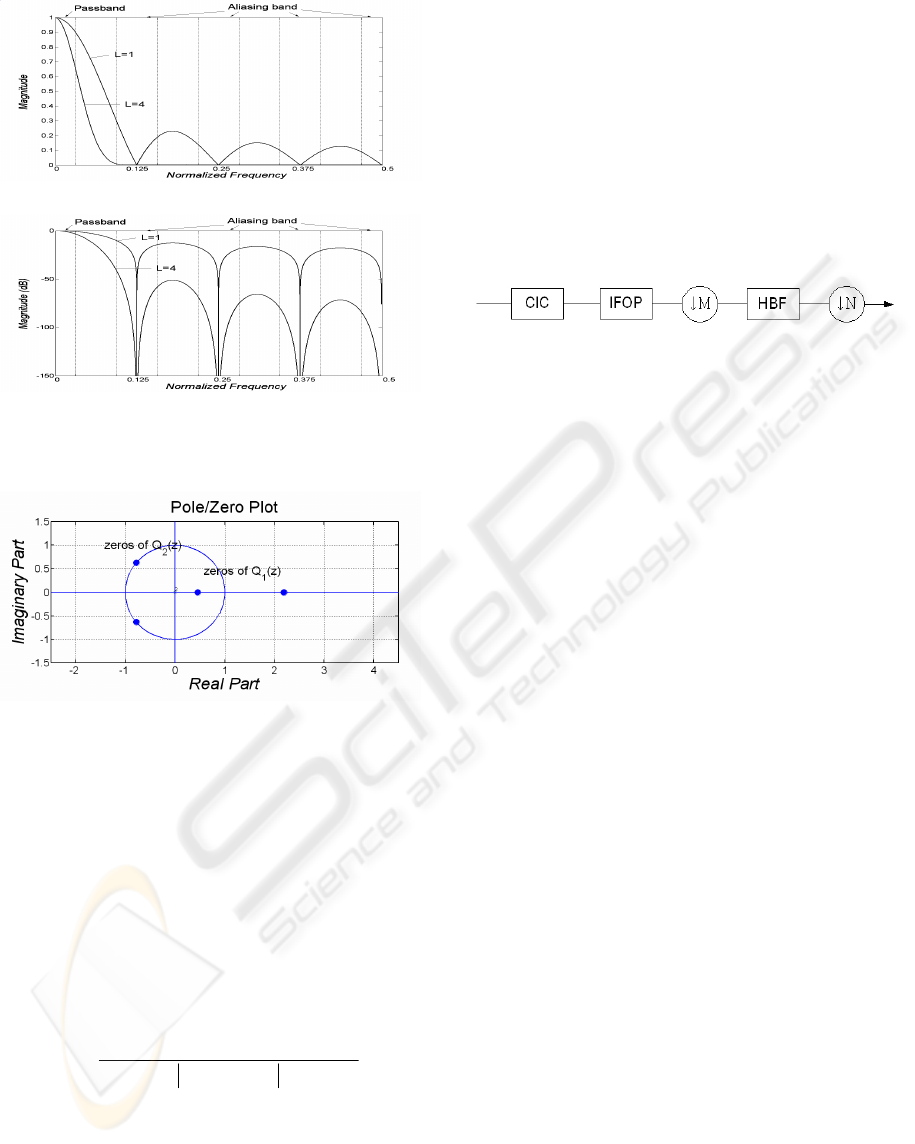
(a)
(b)
Figure 1: Frequency response and aliasing band of CIC
filter (M=8, R=1, one halfband filter).
Figure 2: Zeros location of the proposed IFOP filter in z-
plane.
After the stopband attenuation specification is
satisfied, methods for dealing with the passband
ripple can be applied. In a DFDC using CIC filters,
halfband filters usually follow the CIC section, and
therefore aliasing bands are considered instead of a
stopband. When a halfband filter is used, the aliasing
band is determined, as shown in Fig. 1. When two
halfband filters are used, the aliasing band and
passband become narrower by half. To reduce ripple
in the passband and attenuation in the aliasing bands,
we propose the following IFOP
21
43
1
2
21
22
1
)(
pp
zzpzpzp
zP
IIII
I
++
++++
=
−−−−
(2)
In equation (2), the absolute value of the
denominator is for DC increase proportionally to 1,
and I is the interpolation factor. Excluding scaling
and interpolation factors, the basic equation is
represented as
43
1
2
2
1
1
1)(
−−−−
++++= zzpzpzpzP
(3)
To design an optimal IFOP filter, the above basic
equation is factored as
)1)(1(
)()()(
21
2
21
1
21
−−−−
++++=
=
zzqzzq
zQzQzP
(4)
As shown in Fig. 2, the IFOP filter is controlled
for two zeros to place on the real axis, and is used to
improve the passband ripple of the CIC filter. The
filter is determined for two zeros to place on the unit
circle, and used to improve aliasing band attenuation
of the CIC filter. The overall proposed DFDC
structure is shown in Fig. 3.
Figure 3: Overall proposed DFDC structure.
To examine the effect of the proposed IFOP, the
DFDC structure using one or two halfband filters
was investigated. Passband ripple and aliasing band
attenuation of the proposed DFDC with IFOP are
compared with three other structures which are ISOP
structure [4], CIC only structure[1], and Sharpened
structure[2], respectively. Results are summarized in
Table 1. As shown in Table 1, ripple in the passband
and attenuation in the aliasing band of the proposed
IFOP are improved simultaneously. In the case of
L=4, R=1, and one halfband filter, the passband
ripple and aliasing band attenuation of the CIC-only
structure are 3.593dB and 41.314dB, respectively.
And those of the ISOP structure are 0.416dB and
38.138dB, respectively, where it is shown that the
passband ripple is improved, but aliasing band
attenuation is worsened. However, those of the
proposed IFOP structure are improved to 0.308dB
and 62.256dB, representing better results than those
of the ISOP method. In a two-halfband case
simulation, Table 1 shows that the proposed
structure provides better performance. The proposed
structure shows better passband ripple and aliasing
band attenuation results. From the given
specifications, the proposed DFDC design procedure
can be summarized as
(1) CIC and halfband filters specification decision
1-1 M, R, L decision for CIC filter
1-2 Number and specification decision for halfband
filters
(2) CIC and halfband filters design
2-1 Observation of frequency responses
2-2 Target frequency decision of stopband or
aliasing band
(3) IFOP design
3-1 Value of I decision
3-2 Minimization of aliasing band attenuation
through adjusting the
2
q
SIGMAP 2007 - International Conference on Signal Processing and Multimedia Applications
166
3-3 Minimization of passband ripple through
adjusting the
1
q
3-4 From the and
1
q ,
2
q IFOP decision
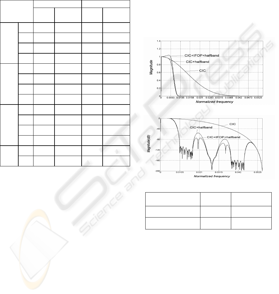
Table 1: Passband droop and aliasing attenuation of the
CIC-only, Sharpened, ISOP, and IFOP(one halfband:
1/(4M), two half band: 1/(8M)).
3 DESIGN EXAMPLES
3.1 Example 1
Using the proposed method, we demonstrate an
example of a DFDC design with a decimation factor
of 36. Overall specifications of the passband
frequency and ripple are 0.00525 and 0.2dB,
respectively. The specifications of the stopband
frequency and attenuation are 0.0105 and 70dB,
respectively. Since the decimation factor is 36, we
choose a factor of 18 for the CIC and a factor of 2
for the halfband filter to satisfy these specifications.
Desired parameters of the CIC filter are R=1, M=18
and L=5. The halfband filter used in this design
example is typical. The combined frequency
response of the CIC and halfband section is shown
in Fig. 4. As shown, the passband ripple and
stopband attenuation are 1.07dB and 55.42dB,
respectively. Since the weak points of the stopband
attenuation are
ω
=0.02 and
ω
=0.035, parameter I
of the IFOP is determined with 18. Adjusting value
of the
2
q , zeros of
)(
2
zQ
are placed in
ω
=0.02
and
ω
=0.035. We then adjust
1
q to minimize the
passband ripple. Overall improved passband ripple
and stopband attenuation are 0.1995dB and 74.71dB,
respectively, as shown in Fig. 4. From the obtained
1
q
and
2
q
, system function of the IFOP in this
example is expressed as
72543618
18
2053.04367.05374.04367.02053.0)(
−−−−
+−−−= zzzzzP
(5)
(a)
(b)
DFDCs
passband
ripple(dB)
stopband
attenuation(dB)
CIC+HBF 1.07 55.42
CIC+IFOP+HBF 0.1995 74.71
(c)
Figure 4: Frequency response improved by proposed IFOP
in the design example 1.
3.2 Example 2
The second example is a design for a DFDC with a
decimation factor of 10. Overall specifications of the
passband frequency and ripple are 0.01875 and
0.3dB, respectively. And the specifications of the
stopband frequency and attenuation are 0.0375 and
70dB, respectively. Since the decimation factor is 10,
we choose a factor of 10 for the CIC and a factor of
fc = 1/(4M) fc = 1/(8M)
passband
ripple
aliasing
attenuation
passband
ripple
aliasing
attenuation
L=4,
R=1
0.3081 62.2555 0.0234 102.09
L=4,
R=2
2.2805 56.7509 0.1682 94.416
L=6,
R=1
0.5417 82.9282 0.0316 136.85
Pro-
posed
IFOP
L=6,
R=2
6.3643 80.2976 0.339 128.61
L=4,
R=1
0.4162 38.138 0.04 67.04
L=4,
R=2
4.5393 42.26 0.2615 67.27
L=6,
R=1
0.752 57.334 0.0652 100.56
ISOP
L=6,
R=2
8.7786 65.361 0.555 101.07
L=4,
R=1
3.5926 41.314 0.8751 67.758
L=4,
R=2
15.634 53.355 3.5988 70.518
L=6,
R=1
5.3889 61.971 1.3127 101.63
CIC-
only
L=6,
R=2
23.450 80.033 5.3983 105.78
L=2,
R=1
0.84 32.33 0.062 58.40
Sharpen
ed
L=4,
R=1
2.692 73.14 0.231 126.10
EFFICIENT DIGITAL FREQUENCY DOWN CONVERTER STRUCTURE USING CIC FILTERS AND
INTERPOLATED FOURTH-ORDER POLYNOMIALS
167
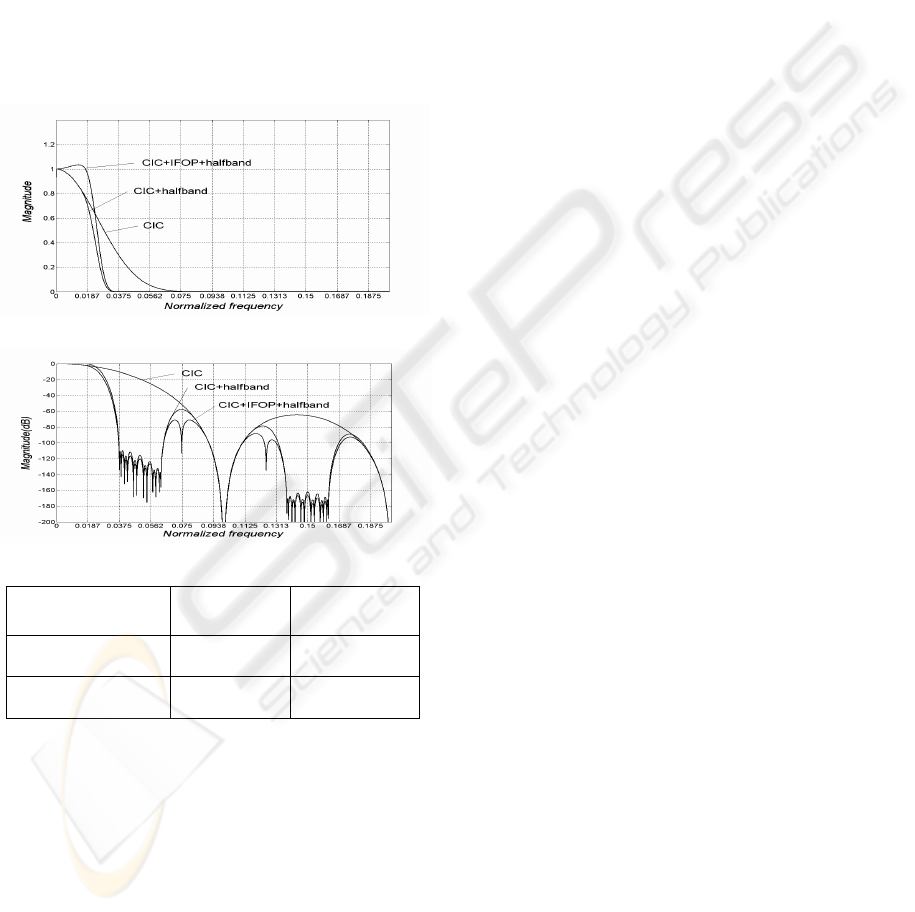
1 for the halfband filter to satisfy these
specifications. Chosen parameters of the CIC filter
are R=1, M=10 and L=5. The halfband filter used in
this design example is also the typical one as in the
previous example. The combined frequency
response of the CIC and halfband section is shown
in Fig. 5. Fig. 5 shows that the passband ripple and
stopband attenuation of the CIC and halfband filter
are 2.94dB and 57.86dB, respectively.
Since the weak points of the stopband attenuation
are
ω
=0.075 and
ω
=0.125, parameter I of the
IFOP is determined with 5. Adjusting the value of
the
2
q , zeros
)(
2
zQ
are placed in
ω
=0.075 and
ω
=0.125.
(a)
(b)
DFDCs
passband
ripple(dB)
stopband
attenuation(dB)
CIC + HBF 2.94 57.86
CIC+IFOP+HBF 0.289 71.27
(c)
Figure 5: Frequency response improved by proposed IFOP
in the design example 2.
We then adjust
1
q to minimize the passband ripple.
Overall improved passband ripple and stopband
attenuation are 0.289dB and 71.27dB, respectively,
as shown in Fig. 5. System function of the IFOP in
this example is expressed as:
2015105
5
4418.05571.07695.05571.04418.0)(
−−−−
+−−−= zzzzzP
(6)
4 CONCLUSIONS
We propose a DFDC structure that can improve the
passband ripple and aliasing band attenuation
simultaneously. By adjusting the zero position of the
two polynomials repeatedly, the overall frequency
response in the passband and aliasing band is
improved, and the coefficients of the IFOP can be
obtained. The implementation cost of the structure is
competitive. Since the proposed DFDC satisfies
linear phase characteristics and needs only three
more multiplications, it can be widely used in
IF(Intermediate Frequency) blocks of the high-speed
communication systems.
REFERENCES
Hogenauer, EB, 1981, ‘An economical class of digital
filters for decimation and interpolation’, IEEE Trans.
Acoust., Speech, Signal Processing, vol. ASSP-29, No.
2, April, pp. 155-162.
Kwentus, AY, Jiang, Z, Willson Jr., AN, 1997,
‘Application of filter sharpening to cascaded integer-
comb decimation filters’, IEEE Trans. Signal
Processing, vol. 45, Feb. pp. 457-467.
Kaiser, J, Hamming, R, 1977, ‘Sharpening the response of
a symmetric nonrecursive filter by multiple use of the
same filter’, IEEE Trans. Acoust., Speech, Signal
Processing, vol. ASSP-25, Oct. pp. 415-422.
Oh, HJ, Kim, S, Choi, G, Lee, YH, 1999, ‘On the use of
interpolated second-order polynomials for efficient
filter design in programmable downconversion’, IEEE
Journal on selected areas in communications, vol. 17,
April, pp. 551-560.
Yang, HK and Snelgrove, WM, 1996, ‘High speed
polyphase CIC decimation filters’, In International
Symposium on Circuits and Systems, Volume 2, pp.
229-232.
Gao, Y, Jia, L, Tenhunen, H, 1999, ‘An improved
architecture and implementation of cascaded
integrator-comb decimation filters’, In International
ASIC / SOC Conference, pp. 391-395.
SIGMAP 2007 - International Conference on Signal Processing and Multimedia Applications
168
