
REALIZATION AND OPTIMIZATION OF H.264 DECODER
FOR DUAL-CORE SOC
Jia-Ming Chen
#,+
, Chiu-Ling Chen
#
,Jian-Liang Luo
+
, Po-Wen Cheng
+
, Chia-Hao Yu
+
Shau-Yin Tseng
+
and Wei-Kuan Shih
#
#
Department of Computer Science National Tsing Hua University Hsinchu, Taiwan, 300, ROC
+
SoC Integration Division of STC, ITRI, Hsinchu, Taiwan, 300, ROC
Keywords: H264/AVC, asymmetric dual-core SoC, parallel programming.
Abstract: This paper presents an H.264/AVC decoder realization on a dual-core SoC (System-on-Chip) platform by
the well-designed macroblock level software partitioning. Furthermore, optimizations of the procedures
executed on each core, and data movement between two cores are captured from software and hardware
techniques. The evaluation results show that a video with D1 (720×480 pixels) resolution can reach real-
time decoding by the implementation, which provides a valuable experience for similar designs.
1 INTRODUCTION
The emerging IP-based multimedia applications,
such as IPTV, video-on-demand services, and video
telephony may benefit from coding efficiency of the
H.264/AVC video standard (ITU-T Rec.H.264, 2003;
Schwarz, 2006) by the lower bit-rates and superior
video quality in comparison to existing video stan-
dards (Wiegand, 2003; Raja, 2004). However, added
features and functionalities of the H.264/AVC codec
involving extra computation complexity that directly
affects the cost effectiveness of commercializing
those applications, especially on resource-constraint
embedded devices. Numerous researches (Horowitz,
2003; Ostermann, 2004; Kalva, 2005) attended to
complexity analysis and profiling of the H.264/AVC
codec, while several approaches (Suh, 2006; Wang,
2004; Chen, 2006; Lin, 2006) came up with reduc-
ing the implementation complexity. Most of the re-
sults were devoted to algorithm level optimization in
which specific characteristics of a single processor
with or without hardware accelerator engines are
utilized.
Instead, in this paper, the H.264/AVC decoder is
realized on an asymmetric dual-core platform, upon
which macroblock (MB) level software partitioning
is applied from data and control flow perspectives.
This approach exploits several advantages. First, I/O
and control-intensive operations (e.g., entropy de-
coding procedure and memory management control
procedures) are separated from computation-
intensive operations handled by distinct cores for the
purpose of smoothly optimization. Second, data
communication can be hidden by pipelined process-
ing between two cores (described later in Section 3)
for saving the space complexity as mentioned in
(Horowitz, 2003). Third and lastly, realizing compu-
tation-intensive software portions on a VLIW DSP
provides programmable and efficient techniques
consistent with comparable audio and video codecs.
Additionally, from the proposed software pipe-
lined processing between two cores (explained later
in Section 3.4), performance improvement can be
reached through optimizing several conceptually
pipelined stages from three aspects: 1) entropy de-
coding on MPU core, 2) data movement between the
MPU and DSP cores, and 3) software portions exe-
cuted on DSP core. These advanced optimizations
complete the entire H.264/AVC decoder of a dual-
core system. The main contribution here brings a
valuable experience in software programming model
for realizing multimedia applications on a dual-core
application processor (particularly equipped with a
VLIW DSP) emerged in the recent marketplace,
such as the TI’s DaVinci™ processor (DaVinci™
technology, 2007).
The rest of the paper is organized as follows. The
PAC DSP is first introduced in Section 2. Then we
explain the software partition flow and data memory
allocation in Section 3. Next, in Section 4, the opti-
mization techniques for enhancing the performance
309
Chen J., Chen C., Luo J., Cheng P., Yu C., Tseng S. and Shih W. (2007).
REALIZATION AND OPTIMIZATION OF H.264 DECODER FOR DUAL-CORE SOC.
In Proceedings of the Second International Conference on Signal Processing and Multimedia Applications, pages 305-312
DOI: 10.5220/0002138403050312
Copyright
c
SciTePress
of decoder are summarized. Experimental results are
given in Section 5, and conclusions are finalized in
Section 6.
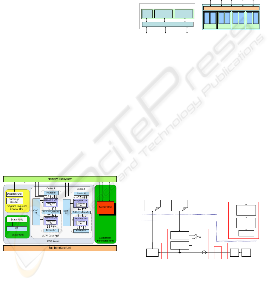
2 OVERVIEW OF THE PAC DSP
The PAC DSP (parallel architecture core digital sig-
nal processor) is a 32-bit fixed-point, 5-way issue,
and 9-stage pipelined DSP designed by STC/ITRI
organization (STC’s Multimedia SoC, 2007) in Tai-
wan. It features low power and high performance
through cluster-based VLIW datapath with parti-
tioned register files, and power/clock gating mecha-
nisms. Figure 2-1 shows the detail architecture of the
PAC DSP, where the major components and features
are explained as follows.
PSCU (Program Sequence Control Unit)—
dispatches instructions to the scalar unit and clus-
tered VLIW data path, executes control flow instruc-
tions, and handles the interrupt/exception events.
Scalar Unit—executes the scalar instructions with
low parallelism but high data dependency, controls
the interfaces of accelerators and power control unit.
Clusters (VLIW datapath)—each cluster owns a
LSU (Load/Store Unit) and an AU (Arithmetic
Unit). The AU provides arithmetic, comparison, data
transfer, bit manipulation, multiplication and accu-
mulation and special instructions, while LSU pro-
vides load/store instructions instead of multiplication
and accumulation instructions. As shown in Figure
2-1, the register files (RFs) within a cluster are dis-
tributed as coefficient, private and Ping-Pong RFs.
Figure 2-1: Architecture of the PAC DSP core.
Memory subsystem—PAC DSP provides 32 kB
instruction memory and 64 kB data memory. The
memory interface unit (MIU) of PAC DSP provides
a maximum bandwidth of 32 bytes, where 8 bytes
for each cluster and CFU, 4 bytes for Scalar Unit
and BIU. In addition, it is byte, half-word, word or
double word addressable according to the instruction
types of the LSU. As shown in Figure 2-2, the data
memory is divided into eight banks in 8 kB
(64×1024 bits), forming four groups for the purpose
of reducing access conflicts for a multi-issued proc-
essor. Especially note that consecutive two data
banks in a group can be configured to be interleav-
ing mode or not, providing convenient data parti-
tions for multimedia applications.
Group 1 Group 2 Group 3Group 0
Tag
256x17
16K Byte 16K Byte
ICH
Instruction Cache
DSP BIU/Bus ICE
Bank
0
Bank
1
Bank
2
Bank
3
Bank
4
Bank
5
Bank
6
Bank
7
Data Memory Interface Unit
Scalar Cluster1 Cluster2 BIU CFU
(a) Instruction Cache
(b) Data Memory
Figure 2-2: Memory subsystem of the PAC DSP.
3 SOFTWARE PARTITION
AND DATA STRUCTURE
In this section, the software partitioning, MB level
processing flow, and data communication of an
H.264 decoder for an asymmetric dual-core system,
that is, a RISC MPU plus a VLIW PAC DSP, are
described in the following subsections.
3.1 Software Partition
As Figure 3-1 shows, the MPU is in charge of the
entropy decoding (ED) due to inherently table-
lookup and control operations. The inverse quantiza-
tion/inverse transformation (IQ/IT), picture predic-
tive compensation (PPC) and deblocking filter (DF)
processes are handled by the DSP because of natu-
rally computation-intensive property.
Entropy
decode
(slice data)
Reorder
Q
-1
T
-1
MC
Intra
prediction
Filter
F’
n
(reconstructed)
F’
n
(refererence)
Entropy
decode
(sps/pps/sh)
D
F
T
IQ/ITDF
ED
PPC
MPU
MPU
DMA
DMA
DSP
DSP
NAL
NAL
Entropy
decode
(slice data)
Reorder
Q
-1
T
-1
MC
Intra
prediction
Filter
F’
n
(reconstructed)
F’
n
(refererence)
Entropy
decode
(sps/pps/sh)
D
F
T
IQ/ITDF
ED
PPC
MPU
MPU
DMA
DMA
DSP
DSP
NAL
NAL
Figure 3-1: Partitioned decoding flow of H.264/AVC
3.2 Data Structure
and Memory Allocation
In terms of MB decoding flow, and preventing con-
flict of data access to maximizing the throughput
SIGMAP 2007 - International Conference on Signal Processing and Multimedia Applications
310
and parallelism, decoding video data should be well-
organized mapped into the data memory of PAC
DSP. Taking a D1 (720×480) video clip as an exam-
ple, Figure 3-2 displays its memory allocation onto
the data memory of PAC DSP results in 45×30 MBs
in raster order. The MBs of each row is equally di-
vided into four parts spreading amount distinct
banks of the data memory with repeatedly sequence
group index 0, 1, 2, 3, therefore preventing data ac-
cess contentions.
0 1 2 3 0 1 2 3
...
1 2 3
0 1 2 3 0 1 2 3 1 2 3
0 1 2 3 0 1 2 3 1 2 3
0 1 2 3 0 1 2 3 1 2 3
...
...
...
0 1 2 3 0 1 2 3 1 2 3
...
0 1 2 3 0 1 2 3 1 2 3
...
30
45
0
0
0
0
0
0
Figure 3-2: Example of data arrangement for D1 resolu-
tion (in the unit of MB).
In other words, the pipelined execution method-
ology (described later in Section 3.4) for an asym-
metric dual-core system can benefit from the alloca-
tion scheme. When IQ/IT is processing the i
th
MB in
the group k, where k =i mod 4, the DMA (triggered
by the MPU) can transfer the (i-1)
th
MB from the
DSP data memory to external memory without ac-
cess conflicts. Meantime, when PPC is processing
the i
th
MB in group k, it can move the residual data
of the next (i+1)
th
MB to the DSP data memory
(through the DMA), result in preventing memory or
data contentions.
For each row, there are 12 MBs and 12 PreRow
data entries (PreRow data will be explained later in
Section 3.3) saved in the first group while the other
groups have 11 MBs and 11 PreRow data entries
respectively. Each MB is stored into a fixed size
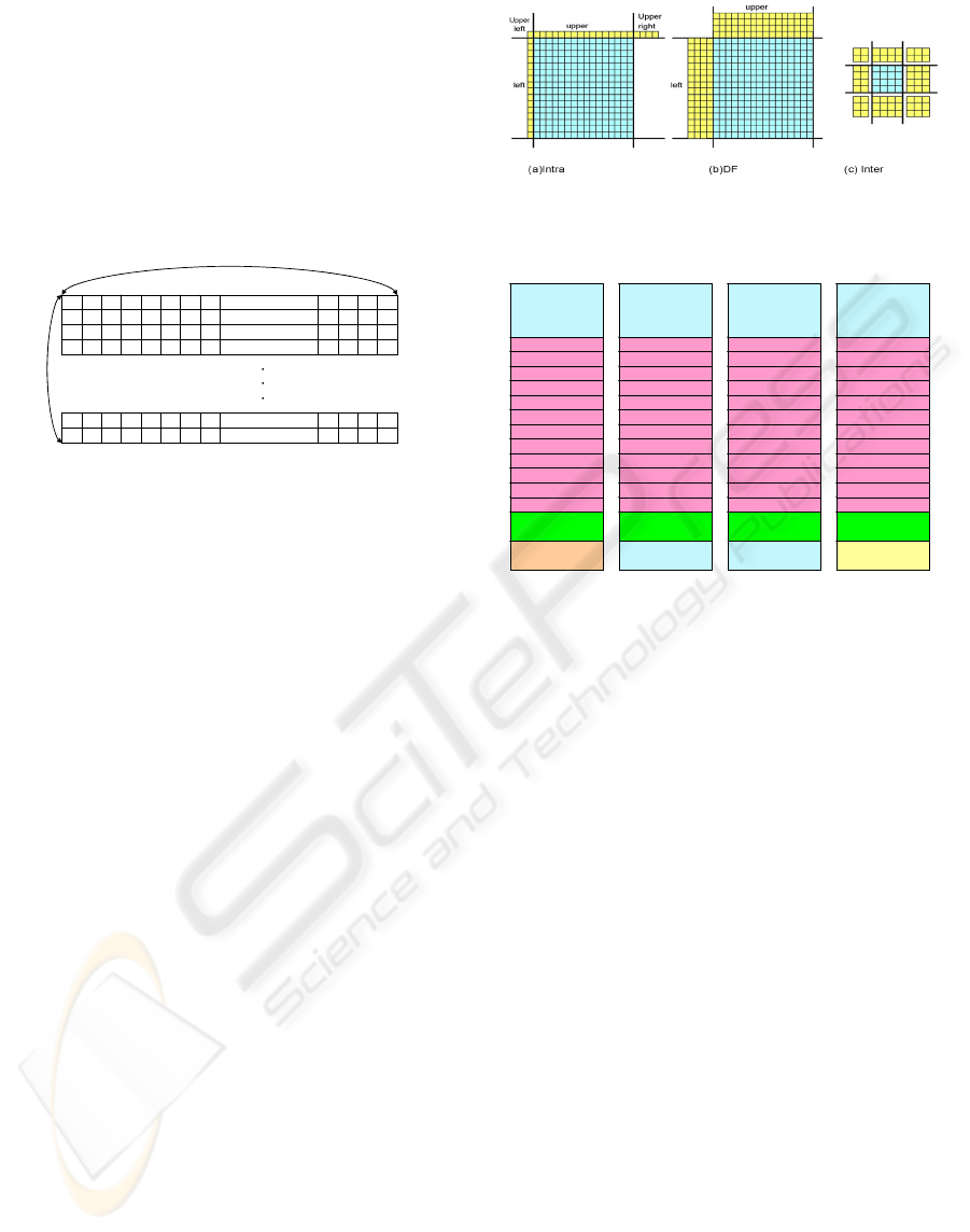
memory space with MB data and reference data.
Data (include MB data and reference data) will
be overwritten when the newest data is transferred to
the memory group. At the moment, PreRow data
needs to be maintained because the reference data
from the left, upper, and upper-right MBs still be
required at inter/intra prediction and DF stage. As
shown in Figure 3-3, the centered 16×16 or 4×4
blocks represent the processing data during the op-
eration; while the blocks (outside the centered block)
represent the referenced PreRow data. In Figure 3-
3(c), the reference data used by inter prediction is
not in the current processing picture, therefore re-
quired data should be transferred via the picture
buffer from the MPU to the DSP through the DMA
controller.
Figure 3-3: Residual blocks with relative reference data
for (a) intra prediction, (b) DF, and (c) inter prediction.
Parameter
flag
MB data
&reference
MB data
&reference
MB data
&reference
MB data
&reference
PreRow data[1]
PreRow data[2]
PreRow data[3]
PreRow data[4]
PreRow data[5]
PreRow data[6]
PreRow data[7]
PreRow data[8]
PreRow data[9]
PreRow data[10]
PreRow data[11]
PreRow data[12]
temp
PreRow data[1]
PreRow data[2]
PreRow data[3]
PreRow data[4]
PreRow data[5]
PreRow data[6]
PreRow data[7]
PreRow data[8]
PreRow data[9]
PreRow data[10]
PreRow data[11]
PreRow data[12]
PreRow data[1]
PreRow data[2]
PreRow data[3]
PreRow data[4]
PreRow data[5]
PreRow data[6]
PreRow data[7]
PreRow data[8]
PreRow data[9]
PreRow data[10]
PreRow data[11]
PreRow data[12]
PreRow data[1]
PreRow data[2]
PreRow data[3]
PreRow data[4]
PreRow data[5]
PreRow data[6]
PreRow data[7]
PreRow data[8]
PreRow data[9]
PreRow data[10]
PreRow data[11]
PreRow data[12]
Parameter
flag
Group0 Group1 Group2 Group3
MB data
&reference
MB data
&reference
MB data
&reference
MB data
&reference
PreRow data[1]
PreRow data[2]
PreRow data[3]
PreRow data[4]
PreRow data[5]
PreRow data[6]
PreRow data[7]
PreRow data[8]
PreRow data[9]
PreRow data[10]
PreRow data[11]
PreRow data[12]
temp
PreRow data[1]
PreRow data[2]
PreRow data[3]
PreRow data[4]
PreRow data[5]
PreRow data[6]
PreRow data[7]
PreRow data[8]
PreRow data[9]
PreRow data[10]
PreRow data[11]
PreRow data[12]
PreRow data[1]
PreRow data[2]
PreRow data[3]
PreRow data[4]
PreRow data[5]
PreRow data[6]
PreRow data[7]
PreRow data[8]
PreRow data[9]
PreRow data[10]
PreRow data[11]
PreRow data[12]
PreRow data[1]
PreRow data[2]
PreRow data[3]
PreRow data[4]
PreRow data[5]
PreRow data[6]
PreRow data[7]
PreRow data[8]
PreRow data[9]
PreRow data[10]
PreRow data[11]
PreRow data[12]
Parameter
flag
MB data
&reference
MB data
&reference
MB data
&reference
MB data
&reference
PreRow data[1]
PreRow data[2]
PreRow data[3]
PreRow data[4]
PreRow data[5]
PreRow data[6]
PreRow data[7]
PreRow data[8]
PreRow data[9]
PreRow data[10]
PreRow data[11]
PreRow data[12]
temp
PreRow data[1]
PreRow data[2]
PreRow data[3]
PreRow data[4]
PreRow data[5]
PreRow data[6]
PreRow data[7]
PreRow data[8]
PreRow data[9]
PreRow data[10]
PreRow data[11]
PreRow data[12]
PreRow data[1]
PreRow data[2]
PreRow data[3]
PreRow data[4]
PreRow data[5]
PreRow data[6]
PreRow data[7]
PreRow data[8]
PreRow data[9]
PreRow data[10]
PreRow data[11]
PreRow data[12]
PreRow data[1]
PreRow data[2]
PreRow data[3]
PreRow data[4]
PreRow data[5]
PreRow data[6]
PreRow data[7]
PreRow data[8]
PreRow data[9]
PreRow data[10]
PreRow data[11]
PreRow data[12]
Parameter
flag
Group0 Group1 Group2 Group3
MB data
&reference
MB data
&reference
MB data
&reference
MB data
&reference
PreRow data[1]
PreRow data[2]
PreRow data[3]
PreRow data[4]
PreRow data[5]
PreRow data[6]
PreRow data[7]
PreRow data[8]
PreRow data[9]
PreRow data[10]
PreRow data[11]
PreRow data[12]
temp
PreRow data[1]
PreRow data[2]
PreRow data[3]
PreRow data[4]
PreRow data[5]
PreRow data[6]
PreRow data[7]
PreRow data[8]
PreRow data[9]
PreRow data[10]
PreRow data[11]
PreRow data[12]
PreRow data[1]
PreRow data[2]
PreRow data[3]
PreRow data[4]
PreRow data[5]
PreRow data[6]
PreRow data[7]
PreRow data[8]
PreRow data[9]
PreRow data[10]
PreRow data[11]
PreRow data[12]
PreRow data[1]
PreRow data[2]
PreRow data[3]
PreRow data[4]
PreRow data[5]
PreRow data[6]
PreRow data[7]
PreRow data[8]
PreRow data[9]
PreRow data[10]
PreRow data[11]
PreRow data[12]
Figure 3-4: data layout in DSP local memory (in 4 groups)
After the calculation completed on the 1
st
MB in
the 1
st
row, the reference data (PreRow data) re-
quired by the 1
st
MB in 2
nd
row is saved in the same
group, such that each MB can access the data re-
quired in the same group as well. That is why the
MB is allocated in the groups by index. Figure 3-4
shows the data layout reside in memory partitioned
into 4 groups. Global variables such as parameter
and flag are placed at fixed location in group 0.
Temporarily memory area is located at group 3.
The usage of memory space is assuming the
maximum requirement. For example, (9×9 +3×3)
×16 bytes are needed for reference data, because
(4×4+2×2) ×16 bytes are required in inter prediction
for a MB. Required reference data for each process
is shown in Figure 3-3.
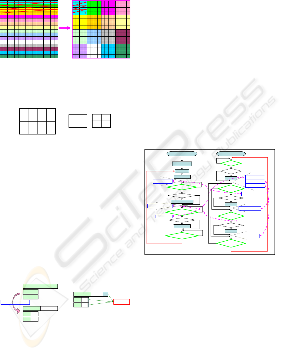
3.3 Data Format Transformation
Compaction
and PreRow Data Reservation
3.3.1 Data Format Transformation
As shown in Figure 3-5, the DFT (Data Format
Transformation) is applied after the IQ/IT for reor-
dering the data in the purpose of smoothly PPC and
DF processing according to the data locality.
REALIZATION AND OPTIMIZATION OF H.264 DECODER FOR DUAL-CORE SOC
311
12
0 1 2 3 4 5 6 7 8 9 10 11 12 13 14 15
0 1 2 3 4 5 6 7 8 9 10 11 12 13 14 15
0 1 2 3 4 5 6 7 8 9 10 11 12 13 14 15
0 1 2 3 4 5 6 7 8 9 10 11 12 13 14 15
0 1 2 3 4 5 6 7 8 9 10 11 12 13 14 15
0 1 2 3 4 5 6 7 8 9 10 11 12 13 14 15
0 1 2 3 4 5 6 7 8 9 10 11 12 13 14 15
0 1 2 3 4 5 6 7 8 9 10 11 12 13 14 15
0 1 2 3 4 5 6 7 8 9 10 11 12 13 14 15
0 1 2 3 4 5 6 7 8 9 10 11 12 13 14 15
0 1 2 3 4 5 6 7 8 9 10 11 12 13 14 15
0 1 2 3 4 5 6 7 8 9 10 11 12 13 14 15
0 1 2 3 4 5 6 7 8 9 10 11 12 13 14 15
0 1 2 3 4 5 6 7 8 9 10 11 12 13 14 15
0 1 2 3 4 5 6 7 8 9 10 11 12 13 14 15
0 1 2 3 4 5 6 7 8 9 10 11 12 13 14 15
0 1 2 3
4 5 6 7
8 9 10 11
12 13 14 15
0 1 2 3
4 5 6 7
8 9 10 11
12 13 14 15
0 1 2 3
4 5 6 7
8 9 10 11
12 13 14 15
0 1 2 3
4 5 6 7
8 9 10 11
12 13 14 15
0 1 2 3
4 5 6 7
8 9 10 11
12 13 14 15
0 1 2 3
4 5 6 7
8 9 10 11
12 13 14 15
0 1 2 3
4 5 6 7
8 9 10 11
12 13 14 15
0 1 2 3
4 5 6 7
8 9 10 11
12 13 14 15
0 1 2 3
4 5 6 7
8 9 10 11
12 13 14 15
0 1 2 3
4 5 6 7
8 9 10 11
12 13 14 15
0 1 2 3
4 5 6 7
8 9 10 11
13 14 15
0 1 2 3
4 5 6 7
8 9 10 11
12 13 14 15
0 1 2 3
4 5 6 7
8 9 10 11
12 13 14 15
0 1 2 3
4 5 6 7
8 9 10 11
12 13 14 15
0 1 2 3
4 5 6 7
8 9 10 11
12 13 14 15
0 1 2 3
4 5 6 7
8 9 10 11
12 13 14 15
(a) (b)
Figure 3-5: Data format transformation.
Figure 3-6 shows the representation of luma (left), and
chroma (Cb and Cr), transforming large Z raster scan
order into little z raster scan order.
0 1
2 3
4 5
6 7
8 9
10 11
12 13
14 15
0 1
2 3
0 1
2 3
Cb
Cr
Figure 3-6: Sub-MB order for luma, and chroma (Cb and
Cr) MBs.
3.3.2 Data Format Compaction
Encoder will extend 1 byte into 2 bytes during mo-
tion estimation stage and transform it into NAL bit-
streams by entropy encoding. Decoder should re-
verse this compress transformation on the residual
data after entropy decoding for getting the original
data. The memory space with size 768 bytes (512
bytes for luma, 128 bytes for chroma Cb, and 128
bytes for chroma Cr) in an MB is reserved for restor-
ing residual data, which is extracted by entropy de-
coding from the bit-streams. After the PPC stage of
decoder, a pixel in 2 bytes will be converted into 1
byte, thus, half of original memory space will be
freed as shown in Figure 3–7. This memory space
can be used for saving pre-column and upper-left
data, which will be used by the next MB at the intra
prediction stage, as shown in Figure 3-3(a).
512 bytes
128 bytes
128 bytes
256
64
64
256
64
64
Data format compact
Luma
Luma
Chroma Cb
Chroma Cr
Chroma Cb
Chroma Cr
256
64
64
256
64
64
Chroma Cb
Chroma Cr
PreColumn
Data
Luma
Figure 3-7: Data format compaction
3.3.3 PreRow Data Reservation
Since reference data required by the PPC and DF
comes from temporal and spatial locations (either in
inter or intra frames within contiguous marcrobloks
as depicted in Figure 3-3). Reserving the whole ref-
erenced frame in the DSP data memory is unpracti-
cal, therefore the proposed PreRow data as shown in
Figure 3-4 can efficiently handle the problem, thus
reducing the frequently data movement between
memories (i.e., the DSP data memory and external
memory) during the PPC and DF operations.
3.4 Program Control Flow
and Data Flow
3.4.1 Control Flow Perspective
MB is the unit of iterations, which means that the
MPU and DSP are synchronized with MB. The con-
trol flow between the MPU and DSP is handled by
the flag resided in share memory. As shown in Fig-
ure 3-8, the MPU and DSP are started at the same
time. The DSP keeps polling the flag until the data
from the MPU is ready and the flag is set. The dot-
ted lines represent the time setting flag and the effect
on MPU and DSP after setting flag.
DF
0
0
ED(MB)
ED
(SPS,PPS)
DMA_W_Done
1
DMA_W(Ref.)
!DF _Done
1
DMA_R
DF_Done
= 0
ED_Done
1
0
DMA_W(ED)
column > 2
column > 4
no
yes
no
yes
DF_Done
column > 3
ED_Done&&
!IT/IQ_Done
DMA_W_Done
&& !PPC_Done
column > 1
column > 2
IT/IQ
PPC
ED_Done = 0
DMA_W_Done = 0
1
0
0
1
0
no
no
no
yes
yes
yes
MPU DSP
!IT/IQ_Done||
!PPC_Done
1
1
0
DF_Done = 1
DF_Done = 1
DF_Done = 1
IT/IQ_Done=1
PPC_Done = 1
ED_Done = 1
DMA_W_Done = 1
Figure 3-8: Control flow perspective in a dual-core system
MPU- Stage ED gets the SPS, PPS fields in
NAL and goes into the main control flow. ED com-
mands DMA to write data on the DSP data memory
after the operation on 1
st
MB data finishes. The flag
ED_Done is set to be 1. Next, check if the
DMA_W_Done is set to be 0. Negative results con-
tinuous polling on DMA_W_Done until the flag is
cleared. If DMA_W_Done is 0, then the condition
column > 2 would be checked for transfer reference
data to the DSP or not. If column <= 2, transfer ac-
tion would be skipped. To determine whether the
MPU should restore the data processed by the DSP
(DMA_R) or not, the flag DF_Done has to be
checked. If DF_Done is 1, routine DMA_R is exe-
cuted and DF_Done is cleared, the value of column
SIGMAP 2007 - International Conference on Signal Processing and Multimedia Applications
312
will also be checked here. If ED_Done is set as 0,
then executes next iteration.
PAC DSP-Flag DF_Done will be checked first.
If it is cleared by the MPU, then the DSP will check
if column > 3 to determine if the execution of DF is
needed. Flags DF_Done, IT/IQ_Done and
PPC_Done will be checked next. If DF_Done = 1,
IT/IQ_Done = 0 and PPC_Done = 0, means that DF
operation completes while IT/IQ and PPC had not.
When IT/IQ_Done=0 and ED_Done=1 (ED finished
and data transferred to the DSP memory), IT/IQ can
be executed. Also, column will be checked here. If
column <= 1, IT/IQ is skipped. Negative results the
execution of IT/IQ. IT/IQ_Done is set for announc-
ing that IT/IQ had been executed, despite the value
of IT/IQ_Done.
The same operation will be applied on PPC.
DMA_W_Done (1 means reference data had been
written to the DSP, 0 means had not) and PPC_Done
(1 means PPC executed, 0 means not) check first. If
DMA_W_Done=1 and PPC_Done = 0, check if col-
umn > 2 for execution of PPC required or not.
PPC_Done is set at last. While IT/IQ_Done =
PPC_Done = 1, next iteration will go on.
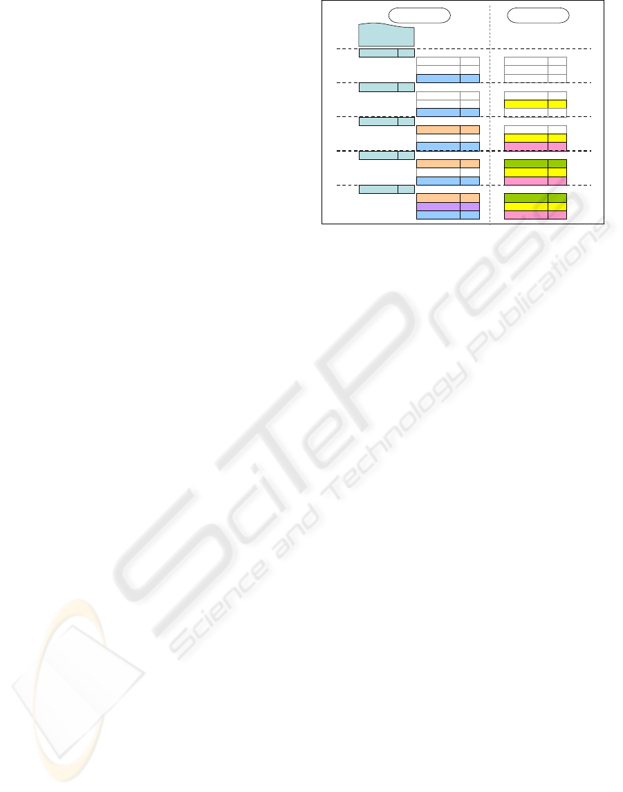
3.4.2 Data Flow Perspective
In Figure 3-9, function blocks in MPU are located at
the left hand side and those in the DSP are located at
the right hand side. Iterations are separated by dotted
lines; functions are represented by blocks with their
names, and the following label m-n means the m
th
slice and the n
th
MB processed by the function.
There are 2 areas of buffer in MPU for storing
data processed by ED. ED will process the data in 1
st
slice and place it in one buffer. Those 2
nd
slices are
placed in the other. As shown in Figure 3-9, ED
(Slice 0) represents the data processed by ED.
The blocks (with grey line) represent the func-
tion of iteration taking no action which corresponds
to the block of column value check in Figure 3-8.
The DMA_W(Ref.) function is executed by the
DMA (commanded via the MPU) for moving refer-
ence data and the DMA_W(ED) is for moving the
residual MB data (after the ED procedure).
IT/IQ+DFT, and PPC+DFC are the respective stage
for MB processing executed by the PAC DSP. The
synchronization between the PAC DSP and MPU is
controlled by polling flags (resided in shared mem-
ory) as shown in Figure 3-8.
DF 0-1DF 0-1
IT/IQ+DFT 0-3IT/IQ+DFT 0-3
PPC+DFC 0-2PPC+DFC 0-2
DMA_R 0-0DMA_R 0-0
DMA_W(Ref.) 0-2DMA_W(Ref.) 0-2
DMA_W(ED) 0-4DMA_W(ED) 0-4
DF 0-0DF 0-0
IT/IQ+DFT 0-2IT/IQ+DFT 0-2
PPC+DFC 0-1PPC+DFC 0-1
DMA_RDMA_R
DMA_W(Ref.) 0-1DMA_W(Ref.) 0-1
DMA_W(ED) 0-3DMA_W(ED) 0-3
DFDF
IT/IQ+DFT 0-1IT/IQ+DFT 0-1
PPC+DFC 0-0PPC+DFC 0-0
DMA_RDMA_R
DMA_W(Ref.) 0-0DMA_W(Ref.) 0-0
DMA_W(ED) 0-2DMA_W(ED) 0-2
DFDF
IT/IQ+DFT 0-0IT/IQ+DFT 0-0
PPC+DFCPPC+DFC
DMA_RDMA_R
DMA_W(Ref.)DMA_W(Ref.)
DMA_W(ED) 0-1DMA_W(ED) 0-1
DFDF
IT/IQ+DFTIT/IQ+DFT
PPC+DFCPPC+DFC
DMA_RDMA_R
DMA_W(Ref.)DMA_W(Ref.)
DMA_W(ED) 0-0DMA_W(ED) 0-0
ED (slice 0)
ED 1-0ED 1-0
ED 1-1ED 1-1
ED 1-2ED 1-2
ED 1-3ED 1-3
ED 1-4ED 1-4
Iteration 1
Iteration 2
Iteration 3
Iteration 4
Iteration 5
MPU DSP
Figure 3-9: Data flow perspective in a dual-core system.
4 OPTIMIZATION
Based on the proposed MB level parallel processing
among two cores, optimization can be achieved from
three aspects of the ED procedure on MPU core,
data communication among two cores, and the pro-
cedures, such as IT/IQ, PPC, and DF executed on
PAC DSP core. The detail optimization techniques
of each landscape are described separately in the
following subsections.
4.1 Entropy Decoding on MPU
The performance of ED procedure can be improved
from the dominated kernel algorithm, Context-
Adaptive Variable Length Coding (CAVLC).
Through statistic analysis of various typical video
clips, we found that around 60% of 4×4 blocks de-
coded from bitstreams appeared in 500 bitstream
patterns within length of 12 bits (especially around
87% for length of 8 bits). Therefore designing a bit-
stream pattern table of these 500 bitstream patterns
to directly decoding the 4×4 blocks (via table lookup)
can improve the ED substantially. Furthermore the
bitstream pattern table can be constructed by sepa-
rating into four 8-bit pattern tables and twenty-one
4-bit pattern tables for the purpose of saving mem-
ory usage instead of using a single 12-bit pattern
table. Accordingly a two-phase pattern search algo-
rithm is derived (as shown in Figure 4-1) to speedup
the CAVLC decoding algorithm contained in the ED
procedure executed on the MPU core. Detail infor-
mation can be found in (Tseng, 2006).
REALIZATION AND OPTIMIZATION OF H.264 DECODER FOR DUAL-CORE SOC
313
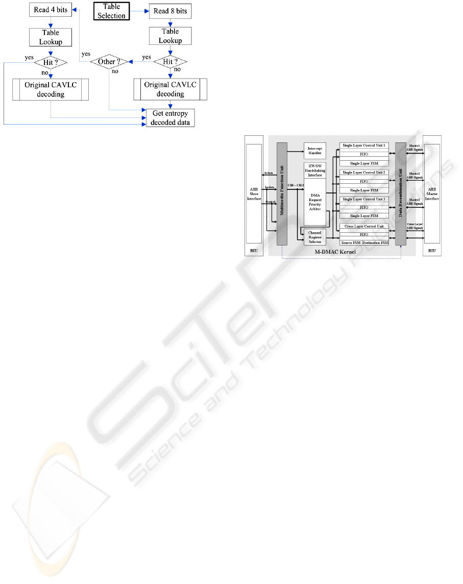
Figure 4-1: Two-phase pattern search algorithm of
CAVLC decoding.
4.2 Data Communication among MPU
and PAC DSP
The data movement between two cores is accom-
plished by DMA controller (commended by the
MPU). However, large amount of small-size refer-
ence data (as depicted in Figure 3-3) is required for
inter prediction of MBs, result in too frequently set-
ting the DMA channels. Additionally, the reference
data are located in two-dimension (2D) mode and
spread randomly, which hurts a traditional DMA in
transforming the 2D coordination into physical ad-
dress in terms of longer channel register setting time.
Moreover, in general the addresses of the reference
data are non-word alignment, since the widths of
reference blocks are often odd and determined dy-
namically. This phenomenon forces a traditional
DMA to transfer the data in a unit of byte, degrading
bus bandwidth utilization. Therefore, to tackle three
major inherently issues of moving reference data
(between two cores), a multimedia enhanced DMA
controller (or so called M-DMAC) is proposed to
replace original used DesignWare DMAC (so called
DW-DMAC) provided by Synopsys company.
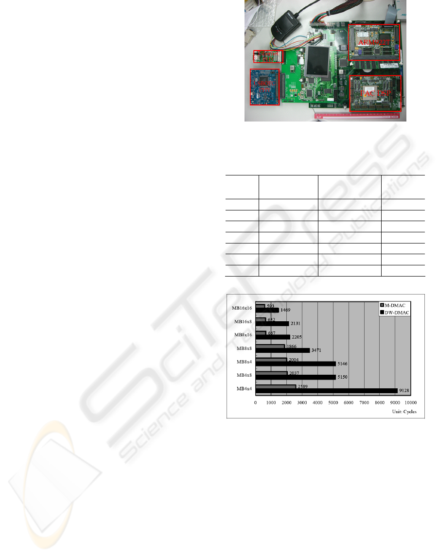
Figure 4-2 shows the architecture of proposed
M-DMAC, where two functional units, Multimedia
Functional Unit (MFU), and Data Recombination
Unit (DRU) are introduced. On the one hand, DRU
handles recombining of 2D source blocks, facilitat-
ing M-DMAC to transfer non-word alignment ad-
dress. The M-DMAC supports four transfer modes
(i.e., any combination of 1D and 2D), and sixteen
physical channels to shorten the busy waiting time
of application programs or issued interrupts. On the
other hand, MFU supports not only physical address
interface for linear data transmission, but also 2D
awareness interface, where the block size, and the
X-Y coordination of 2D block, width, height, and
starting address of source/destination video frames.
Moreover, there are also motion vector parameters
describing the locations of source reference blocks.
To reduce the setting times of channel registers,
common block size and frame resolution are built
inside MFU and can be designated through an index
table. For 2D block, user can directly input 2D data
information via the 2D awareness interface. Thereaf-
ter the 2D information is transformed into physical
address, thereby reducing the time for calculating
physical address, and achieving high parallelism
between application programs and M-DMAC opera-
tions.
Figure 4-2: Architecture of M-DMAC.
4.3 Program Optimization on
PAC DSP
Computation intensive procedures, such as IT/IQ,
PPC, and DF, executed on the PAC DSP are opti-
mized by hand-coded assembly programs adhere to
fully utilized the characteristics of PAC DSP. The
programming techniques are summarized as follows.
Data partitioning for two VLIW clusters
Actually PAC DSP is a 5-way issue VLIW DSP
processor, classifying into one AU plus one LSU per
cluster, and one Scalar Unit. Therefore, the cluster-
based VLIW datapath inherently towards data parti-
tioning, that makes fully parallelization for MB
processing. For example, all MBs (no matter luma or
chroma) can be decomposed into 4x4 sub-MBs, and
one 4x4 can be further divided into 4x2 or 2x4 data
blocks processed by each cluster. Especially, Cb and
Cr are processed on distinct cluster due to their data
independent property. Higher IPC (instruction per
cycle) can be reached naturally via this scheme on
PAC DSP.
Data packing/unpacking with SIMD (single
instruction and multiple data)
PAC DSP provides efficient data packing and un-
packing instructions, which makes smoothly SIMD
utilization on each cluster. Ideally 8-bit data process-
SIGMAP 2007 - International Conference on Signal Processing and Multimedia Applications
314
ing can achieved double quad-speed with minor
overhead for packing/unpacking (from/to memory).
Strength reduction for multiplication opera-
tions
Multiplications in the IQ/IT (matrix operations) and
PPC (6-tape filter operations) procedures of the
H.264/AVC decoder can be transformed into addi-
tion and subtraction operations. Furthermore, those
operations can be well organized into special MAC
(multiply-and-accumulate) and Butterfly operations
provided by the PAC DSP instructions.
Loop unrolling and Software pipelining
Through these schemes, NOP operations in loop
kernels for each procedures executed on the PAC
DSP can be squeezed out to improve the perform-
ance. A lot of efforts have paid on this, since data
dependence is the critical issue in our MB level de-
coding flow between two cores (MPU and DSP)
where inter-loop unrolling and software pipelining
need to be carefully handled. Especially note that
slightly refinement in the deepest loop kernel still
can achieve a great improvement substantially due to
the enormous data proportional to the video resolu-
tion.
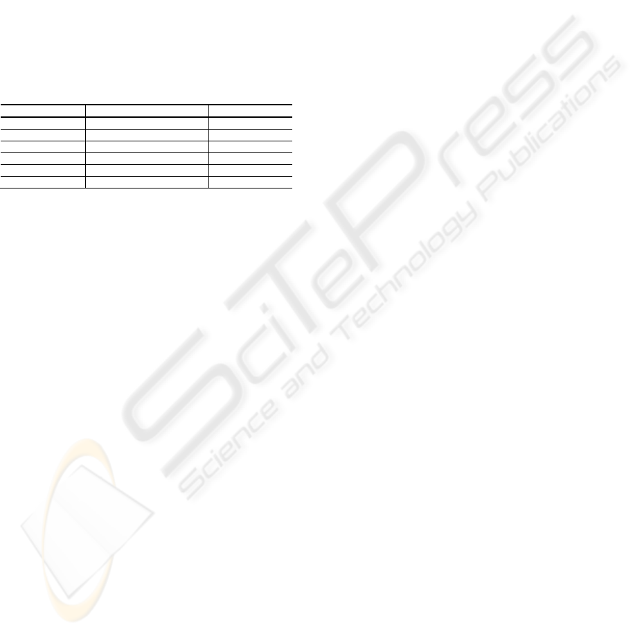
5 EXPERIMENTAL RESULTS
As shown in Figure 5-1, a development board of the
PAC SoC platform (STC’s Multimedia SoC, 2007)
to evaluate the implementation, where the MPU is
ARM922T running at 150MHz with 33MHz internal
frequency, the system bus is AMBA 2.0 lite running
at 22MHz frequency with multi-layer AHBs, and the
M-DMAC is a FPGA module running the same fre-
quency as AHB bus, and a PAC DSP (also imple-
mented by the FPGA module) running at 24MHz.
The following subparagraphs describe the compara-
ble results of each portion.
ED on MPU core-Table 5-1 shows the results of
devised two-phase pattern search algorithm for
CAVLC decoding in ED executed on the MPU core,
achieving around 10% improvement in average
comparing to standard ED with normal CAVLC
decoding scheme.
Data movement between two cores-Figure 5-2
displays the efficiency of proposed M-DMAC in
terms of inter prediction with various MB partitions
result in 2~4 times faster than DW-DMAC.
Figure 5-1: Development board of the PAC SoC.
Table 5-1: Performance improvement of two-phase pattern
search algorithm for typical video sequences.
Figure 5-2: Performance comparison between M-DMAC,
and DW-DMAC with various MB partitions.
Procedures on PAC DSP core-Table 5-2 shows
the results of procedures executed on the PAC DSP,
where intra prediction has the largest code size in-
curred by code unrolling for all different cases. The
best case of DF procedure produced 1000 cycle
counts when BS (boundary strength value) equals
zero. Statistically, the probability of BS equals to
zero is around 71% in average and 47.3% in worst
case. Thus evaluation results achieved around 2000
cycles in average. Due to a great amount of cycle
count wasting on the interpolation operation, the
inter prediction process has large cycle count around
(640~2800) + 200. Also, the evaluation displayed
Video
sequence
Entropy decoding
with normal
CAVLC decoding
Entropy decoding
with two-phase
pattern search method
Improvement
Claire 14,612,810 12,738,779 12.82%
Highway 20,639,203 19,572,458 14.86%
Carphone 29,777,102 25,990,674 12.72%
Silent 30,334,038 26,373,234 13.06%
News 30,725,393 28,079,039 8.61%
Foreman 34,192,569 29,959,594 12.38%
Mobile 89,094,039 83,645,173 6.12%
REALIZATION AND OPTIMIZATION OF H.264 DECODER FOR DUAL-CORE SOC
315
that the average cycle count of interpolation opera-
tion is 1500. For IQ/IT, the skip mode has probabil-
ity 45% in average and 6% in worst case, which re-
sults the best case cycle count 200. The average cy-
cle count spent in IT/IQ is around 1500 cycles.
Therefore, the implementation on the DSP core
spends around 5000 cycles per MB processing in
average, which is under the required cycle counts
per MB of decoding an H.264 video sequence with
D1 (720×480) resolution in real time (i.e., 6173 cy-
cles, derived from (250×10
6
) / (45×30) / 30 when the
DSP is running at 250 MHz), therefore achieving
real-time decoding in most cases.
Table 5-2: Execution cycles of the procedures on the PAC
DSP.
Functions Cycle counts Code size(kB)
DSP_main 150 1.5
IQ/IT 200~2600 6.4
Intra prediction (300~1900) + (200~400) 18.7
Inter prediction (640~2800) + 200 11.2
DF 1000~5000 8.9
TOTAL 1850~10600 46.7
Finally, the prototyping SoC platform with an
ARM core and FPGA module (for the PAC DSP)
reveals that, even in low profile specification, the
whole decoding system still can process up to 26 fps
at QCIF resolution, which can be expected at higher
specification with a real-chip dual-core SoC (e.g.,
PAC DSP@250MHz with higher bus frequency) for
decoding a video with D1 resolution in real-time.
6 CONCLUSIONS
In this paper, a software programming model for
H.264/AVC decoder on an asymmetric dual-core
SoC platform, equipped with a VLIW PAC DSP
coprocessor is presented. The decoding throughput
is achieved by well-organized software partitioning
flow between two cores, efficient data movement
from MPU to PAC DSP and vice versa, and program
optimization both on the MPU and PAC DSP. The
analysis shows that the implementation can achieve
real-time decoding at D1 resolution, which provides
a valuable experience for similar implementations.
REFERENCES
Chen, Y.-K. Li, E., Zhou, X., Ge, S., 2006. Implementa-
tion of H.264 Encoder and Decoder on Personal Com-
puters. In Journal of Visual Communications and Im-
age Representations, vol. 17, no. 2, pp. 509-532.
DaVinci™ technology from TI.(n.d.). Retrieved March 2,
2007,from:http://www.ti.com/corp/docs/landing/davin
ci/index.html
Horowitz, M., Joch, A., Kossentini, F., Hallapuro, A.,
2003. H.264/AVC baseline profile decoder complexity
analysis. IEEE Transactions on Circuits and Systems
for Video Technology, vol.13, issue 7, pp. 704-716.
ITU-T Rec.H.264, ISO/IEC 14496-10, 2003. Advanced
video coding, Final Draft International Standard, JVT-
G050r1, Geneva, Switzerland
Kalva, H., Furht, B., 2005. Complexity Estimation of the
H.264 Coded Video Bitstreams. Computer Journal,
vol. 48, issue 5, pp. 504-513.
Lin, H.-C., Wang, Y.-J., Cheng, K.-T., Yeh, S.-Y., Chen,
W.-N., Tsai, C.-Y., Chang, T.-S., Hang, H.-M., 2006.
Algorithm and DSP implementation of H.264/AVC. In
ASP-DAC’06, 11-th Asia and South Pacific Design
Automation Conference, Yokohama, Japan.
Ostermann, J., Bormans, J., List, P., Marpe, D., Narro-
schke, M., Pereira, F., Stockhammer, T., Wedi, T.,
2004. Video coding with H. 264/AVC: tools, perform-
ance, and complexity. Circuits and Systems Magazine,
IEEE, vol. 4, no. 1, pp. 728.
Raja, G., Mirza, M. J., 2004. Performance comparison of
advanced video coding H.264 standard with baseline
H.263 and H.263+ standards. In ISCIT’04, IEEE In-
ternational Symposium on Communications and In-
formation Technology, vol.2, pp. 743-746.
Schwarz, H., Marpe, D., Wiegand, T., 2006. Overview of
the Scalable H.264/MPEG4-AVC Extension. In
ICIP’06, IEEE International Conference on Image
Processing, pp. 161-164
STC’s Multimedia SoC. (n.d.). Retrieved March, 2, 2007,
from: http://int.stc.itri.org.tw/eng/research/multimedia-
soc.jsp?tree_idx=0200
Suh, H.-L., Jeong, H.-K., Ji, H.-P., Seon, W.-K., Suki, K.,
2006. Implementation of H.264/AVC Decoder for
Mobile Video Applications. In ISCAS’06, IEEE Inter-
national Symposium on Circuits and Systems .
Tseng, S.-Y., Hsieh, T.-W., 2006. A Pattern-Search
Method for H.264/AVC CAVLC Decoding. In
ICME’06, IEEE International Conference on Multi-
media & Expo, pp. 1073-1076.
Wang, S., Yang, Y., Li, C., Tung, Y., Wu, J., 2004. The
optimization of H.264/AVC baseline decoder on low-
cost TriMedia DSP processor. In proceedings of SPIE,
vol. 5558, p. 524.
Wiegand, T., Schwarz, H., Joch, A., Kossentini, F.,
Sullivan, G., 2003. Rate-constrained coder control and
comparison of video coding standards. IEEE Transac-
tions on Circuits and Systems for Video Technology,
vol. 13, pp. 688–703.
SIGMAP 2007 - International Conference on Signal Processing and Multimedia Applications
316
