
TURBO SPACE TIME CODES FOR TAILBITING
TRANSMISSION
Piotr Remlein and Filip Łęcki
Faculty of Electronics and Telecommunications, Poznan University of Technology, Piotrowo 3a; 60-965 Poznan, Poland
Keywords: Space time encoding, turbo encoding, MIMO channel, codes over ring.
Abstract: This paper studies a novel technique that combines turbo tailbiting codes over the ring with symbol
interleaved space-time modulation. After initial theoretical introduction and analysis, the simulation results
are presented. It is shown that for different antenna array sizes, different packet sizes and two kinds of
channels the Turbo space time tailbiting coding have a clear advantage over the transmission method with
direct truncation.
1 INTRODUCTION
Driven by the increasing need for capacity and
system availability whilst using the same bandwidth,
multiple-input-multiple-output (MIMO) technique
has become an interesting extension to wireless
communication systems (Vucetic, 2003). With the
introduction of multiple antenna arrays came the
need for proper channel coding and transmission
method. Recently, in order to improve the error
performance of wireless systems techniques
combining space-time (ST) and turbo coding have
been proposed. Typically in such systems packet
data transmission is used. However, in order to use
convolutional codes in the packet transmission we
must convert these codes to block codes. There are
some well known methods for this conversion (Ma,
1986). One of them is called Direct Truncation. The
most popular method is called Tailbiting (TB). In
this method we transmit the convolutional coded
data in a block form without known tail. By framing
coded data we are not adding known bits to the end
of the data information stream (Cox, 1994). Simply
the binary encoder starts and finishes the encoding
process in the same state. This state is not known to
the decoder.
In this paper, we propose a novel technique that
combines turbo tailbiting codes over the ring with
symbol interleaved space-time modulation. The
turbo encoder consists of two feedback systematic
convolutional encoders over the ring of integers
modulo-M. This encoder is connected to s-random
symbol interleaver and next to space-time
modulator. We investigate the system which
contains a turbo space time encoder over ring
modulo-4 and QPSK modulator.
The performance of the proposed system for
various packet sizes, different number of transmit
antennas and MIMO quasi-static or fast fading
channel is evaluated by simulation.
This paper is organised as follows. Section 2
describes the TB encoding procedure which uses the
feedback systematic convolutional encoders over
ring Z
M
. In Section 3, we present the structure of
space time turbo encoder over ring Z
M
. In Section 4,
the MIMO channel model is described. Section 5
explains iterative decoding with symbol interleaver.
Section 6 presents the simulation results. Finally, a
conclusion is drawn in Section 7.
2 TAILBITING
CONVOLUTIONAL CODES
OVER RING
In this paper we concentrate on the usage of non-
binary codes (Massey, 1989). There are a few
reasons for using them. They have larger Euclidean
distances than codes over GF(2). Moreover, they
make the usage of mapping and set partitioning not
necessary. In the analyzed method we encode and
decode a block of N (M-ary) symbols without a
know tail, thus keeping the effective rate of
transmission.
140
Remlein P. and ŁÄ
´
Zcki F. (2007).
TURBO SPACE TIME CODES FOR TAILBITING TRANSMISSION.
In Proceedings of the Second International Conference on Wireless Information Networks and Systems, pages 140-145
DOI: 10.5220/0002146101400145
Copyright
c
SciTePress
The encoding procedure to achieve this is not
difficult if the structure of the used encoder is
feedforward. Then the starting state depends only on
the m last information symbols in the transmited
packet (m is the number of memory cells in the
encoder). In case of using a recursive systematic
convolutional encoder (RSC) with feedback (Figure
1) the ending state depends on all of the information
symbols in the packet. Finding initial state, wherein
the encoder should start its work and after
processing N symbols to end encoding in the same
state is complex and not always possible (Weiß,
2001).
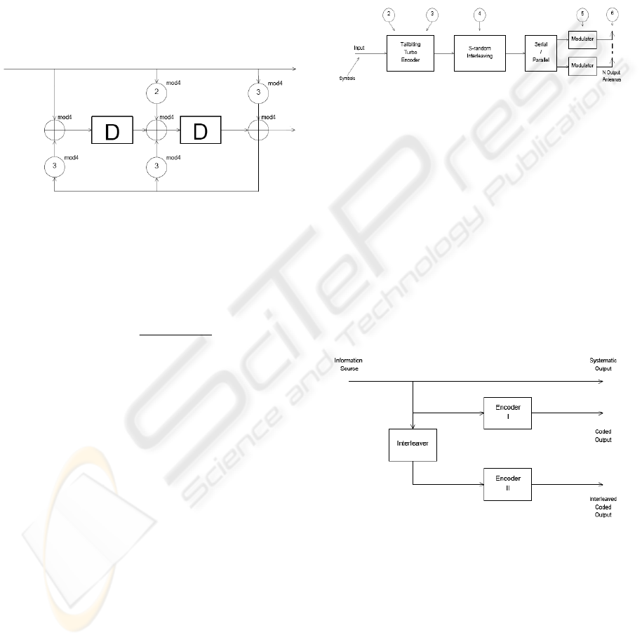
Figure 1: RSC encoder over ring ℜ=Z
4
.
In Figure 1, we show an example of the RSC
encoder over the ring ℜ=Z
4
of integers modulo-4
(Remlein, 2003). The code rate is R=1/2 (k=1, n=2)
and the transfer function matrix is:
At instant t an information vector with M-ary
symbols belonging to the ring Z
M
={0, 1, 2, ... , M-
1}, (ℜ=Z
M
; M=4) inputs the encoder. The
convolutional encoder generates encoded vector
which contains sequence of the symbols elements
belonging to the same ring ℜ=Z
4
.
The encoder coefficients in Fig. 1 are from the
set {0,...,M-1}, M=4. The memory cells are capable
of storing the ring elements. Multiplications and
additions are performed in the ring of integers
modulo-M.
3 TURBO SPACE TIME
ENCODER OVER RING
Model of the system analyzed in this article joins
packet transmission tailbiting convolutional
encoding over the ring with space time encoding.
The convolution codes over the ring Z
M
considered
in (Remlein, 2003) were not optimized for the multi
antennas systems. Authors of this article used these
codes in the system shown in Figure 2. This is a
modification of solution considered in (Stefanov,
2001). We propose placing the tailbiting turbo
encoder over the ring in the transmitter. In our
proposal there is no need to consider set-partitioning
and symbol mapping. The usage of M-symbol
alphabet in the encoder in a natural way maps
symbols into M-PSK signal elements. Every
constellation point has its equivalent symbol.
Figure 2: Transmitter diagram.
The transmitter (Fig. 2) is constructed as
follows:
1. Construct encoder for M symbol alphabet.
2. Fed the turbo encoder with uninterleaved
and interleaved data sequence.
3. Turbo encode the uniterleaved and
interleaved input sequence.
4. Interleave the encoder output sequence in
S-random interleaver.
5. Modulate the signals.
6. Input symbol to different antenna in the
array.
In Figure 3 it is shown the turbo encoder
(Berrou, 1993) used in the transmitter.
Figure 3: Structure of the turbo encoder.
The encoder I and encoder II are RSC encoders
shown in Figure 1. The interleaver is an UMTS type
interleaver (3GPP TS 25.212). The interleaver is
responsible for decorrelating inputs to encoder I and
encoder II.
The S-random interleaver (Dolinar, 1995)
reorders the turbo coded sequence to further
decorrelate the symbols before feeding the antenna
inputs.
⎥
⎥
⎦
⎤
⎢
⎢
⎣
⎡
++
++
=
2
2
331
23
1)(
DD
DD
DG
TURBO SPACE TIME CODES FOR TAILBITING TRANSMISSION
141
The S-random interleaver (S=1,2,...) is a
semirandom interleaver. Each randomly selected
integer is compared with S previously selected
numbers. If the difference between them is smaller
then S, the current selection is rejected and a new
integer is generated. The process repeats until N
distinct integers are selected.
4 CHANNEL MODEL
The telecommunication system with n
T
transmit and
n
R
receive antennas we consider can be described by
the following formula:
ν
+
= Hsy
(1
)
where
1×
∈
T
n
Cs defines the transmission vector,
1×
∈
R
n
Cv defines the additive white Gaussian noise
vector,
TR
nn
CH
×
∈ is the channel matrix, that
describes the connections between the transmitter
and receiver and can be expressed as:
⎥
⎥
⎥
⎥
⎦
⎤
⎢
⎢
⎢
⎢
⎣
⎡
=
MNMM
N
N
H
ααα
ααα
ααα
L
MOMM
L
L
21
22221
11211
(2
)
Where
mn
α
is the complex transmission
coefficient between element m at the transmitter
(TX) and element n at the receiver (RX). To
generate channel matrix H, we used the narrowband
Kronecker model presented in (Ozcelik, 2003). In
this model it is assumed that the receive correlation
matrix is independent of the corresponding transmit
matrix and vice-versa. The channel model used in
this paper was further simplified according to the
assumptions in (Ozcelik, 2003). To calculate the
correlation coefficients between the antennas in the
transmitting as well as in the receiving array, we
followed the approach in (Loyka, 2002).
Figure 4 depicts the influence of distance
between array elements on capacity. The simulations
were made for the case of 2 element arrays. The
solid line presents the idealized case, when no
correlation can be observed among the antennas at
the mobile station (MS). As we can see, the line
representing the distance of 0.5 wavelength, lies
very close to the solid line. Hence, we can assume
that this distance is sufficient for normal operation.
The distance between elements at the Base Station
(BS) is normally much larger than in the Mobile
Station, and it does not have much influence on the
capacity. Therefore, we used for the simulations the
following parameters: BS azimuth spread = 18
o
, BS
distance=10 λ. MS azimuth spread = 90
o
, MS
distance=0.5 λ.
Figure 4: Capacity vs distance between array elements for
2 antennas. BS azimuth spread = 18
o
. MS azimuth spread
= 90
o
.
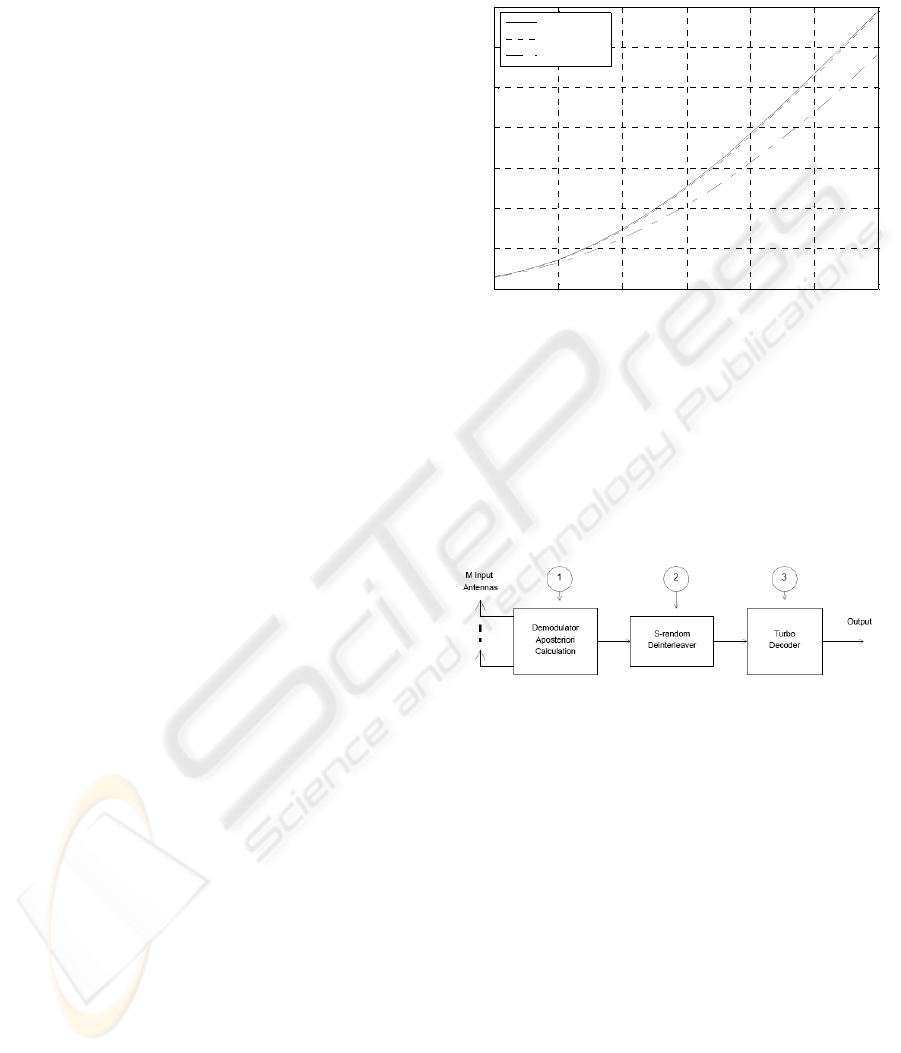
5 RECEIVER
The block scheme of the receiver used in the
analyzed system is shown in Figure 5.
Figure 5: Receiver diagram.
The demodulator performs two operations: it
demodulates the signal and it calculates the
aposteriori values of the received signal. The
demodulated symbols are deinterleaved and fed to
the turbo decoder.
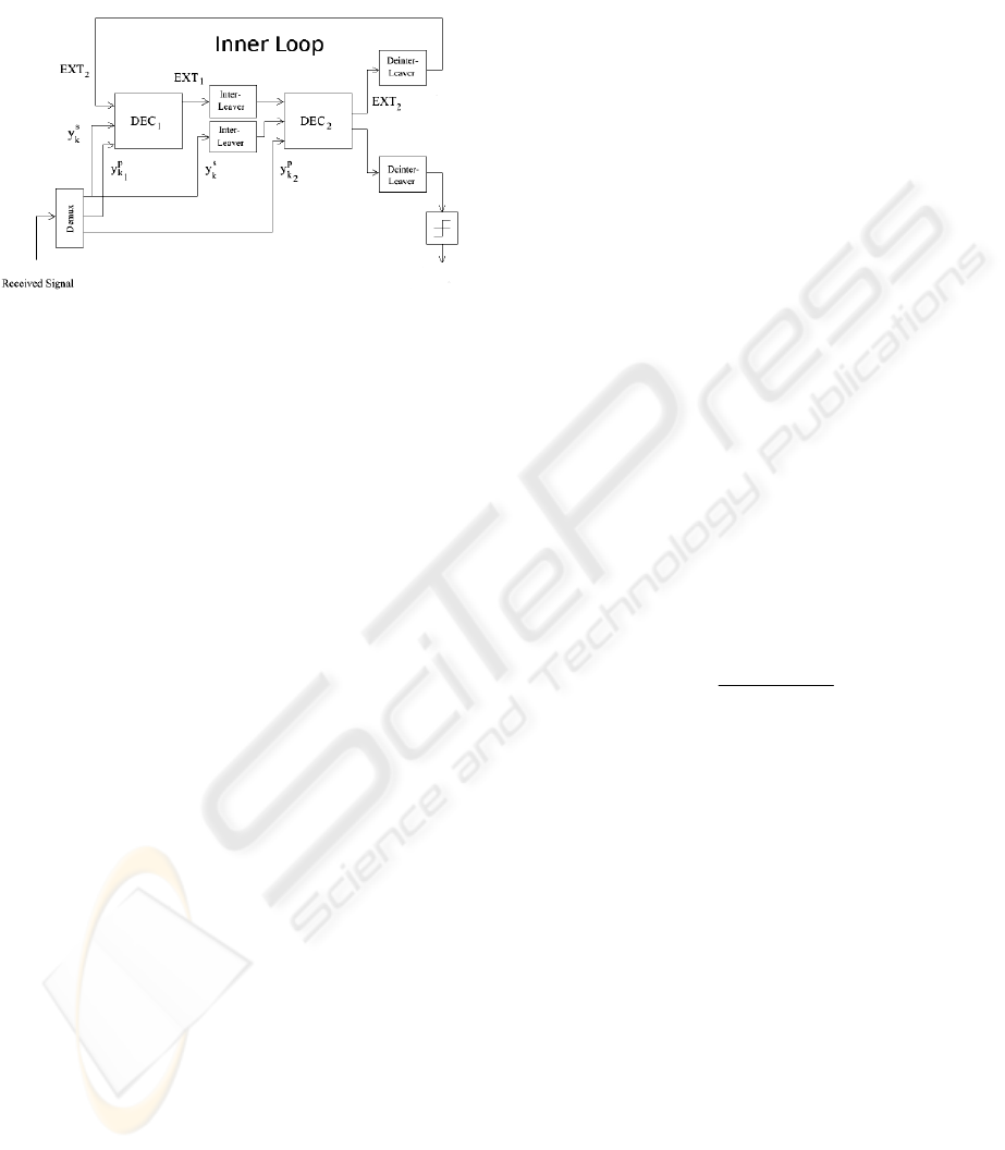
The scheme of the turbo decoder is shown in the
Figure 6. The decoder uses a well known from the
literature connection of two SISO (Soft Input Soft
Output) decoders (Hagenauer, 1996) with feedback.
The crucial and most interesting part of the
decoding process is the iterative exchange of
information between decoders. This is also the
reason for calling this method “turbo”. With each
iteration, the Bit/Symbol error rate drops. Now we
can see, why there is so much research on proper
interleavers. Let us consider a situation when the
channel undergoes a deep fade. With great
probability part of the transmitted signal is lost, but
0 5 10 15 20 25 30
0
2
4
6
8
10
12
14
SNR [dB]
Capacity [bit/sec/Hz]
Decorelated
0.5
λ
0.1
λ
WINSYS 2007 - International Conference on Wireless Information Networks and Systems
142
due to interleaving and trellis decoding, it might be
reconstructed.
Figure 6: Turbo decoder. EXT- extrinsic information,
s
k
y
- systematic information,
p
k
y
1
- parity information from
the first encoder,
p
k
y
1
- parity information from the second
decoder.
The technique that allows the turbo codes to
almost achieve the Shannon bound is in fact the
exchange of information between the decoding
blocks. To process the information in the receiver so
called Soft Input Soft Output Decoder (SISO)
(Hagenauer, 1989) was developed. Our SISO
decoder uses the improved Soft Output Viterbi
Algorithm which is able to decode the non-binary
codes (Cong, 1999). The processing steps of SISO
decoder are explained after the notation is described.
u
i
is the i-th symbol from the alphabet {0,1,...,M-
1};
()
k
sΓ is cumulative metric value at state s
k
;
)](
ˆ
[)(
ˆ
, kjk
sLsL
μ
=
is δ x M reliability measure
matrix stored at each state, where j=k − δ + 1, ..., k,
μ = 0, 1, ...,M − 1, and δ is the size of the decoding
window;
Δ is reliability difference between the survivor at
state s
k
and the most likely path terminating in the
state s
k
with u
j
=μ.
At each state s
k
corresponding to the decoding
time k, SOVA calculates and stores the
()
k
sΓ as in
the normal Viterbi Algorithm, additionally it stores
)(
ˆ
k
sL
. At each step (k+1) for every state s
k+1
the
algorithm evaluates cumulative metric candidates
),(),...,,(
1
1
1
0
+
−
+
ΓΓ
k
M
kkk
ssss originating from s
k
and selects the minimum cumulative metric
)(
1+
Γ
k
s . However, it does not neglect the rest, they
are being stored as competitive paths. After finding
)(
1+
Γ
k
s , the reliability differences Δ can be
calculated in the following way:
{}
),(min),(
1
1,...,0
1 +
−∈
+
Γ−Γ=Δ
k
m
k
Mm
k
m
km
ssss
(3
)
where Δ
m
=0 for the surviving path at state s
k+1
.
We first set
μμ
Δ=
++
)(
ˆ
1,1 kk
sL , because Δμ is the
reliability difference between the survivor at s
k+1
and
the most likely path terminating in state s
k+1
with
u
k+1
= μ. The next step is to update the remaining
values in
)(
ˆ
1, +kj
sL
μ
, j=k-δ+1,...,k based on the
following rule:
{}
{
}
m
m
j
Mm
k
m
j
LsL Δ+=
−∈
+
μμ
,
1,...,0
1,
ˆ
min)(
ˆ
(4
)
where )(
ˆˆ
,,
m
kj
m
j
sLL
μμ
≡ . The modified SOVA
algorithm, shows performance equal to the of Max-
Log-MAP algorithm at a lover computational
expense (Berrou, 1993).
6 SIMULATION RESULTS
The computer simulations were performed in
MATLAB environment. The simulations were
conducted for QPSK modulation and RSC encoder
over ring Z
4
with the transfer function matrix:
In this paper, both quasi-static and fast fading
channels were considered. For quasi static fading, it
is assumed that the fading coefficients are constant
during a packet transmission. These coefficients
vary from one packet to another independently. For
fast fading channels the fading coefficients vary
from one symbol to another independently.
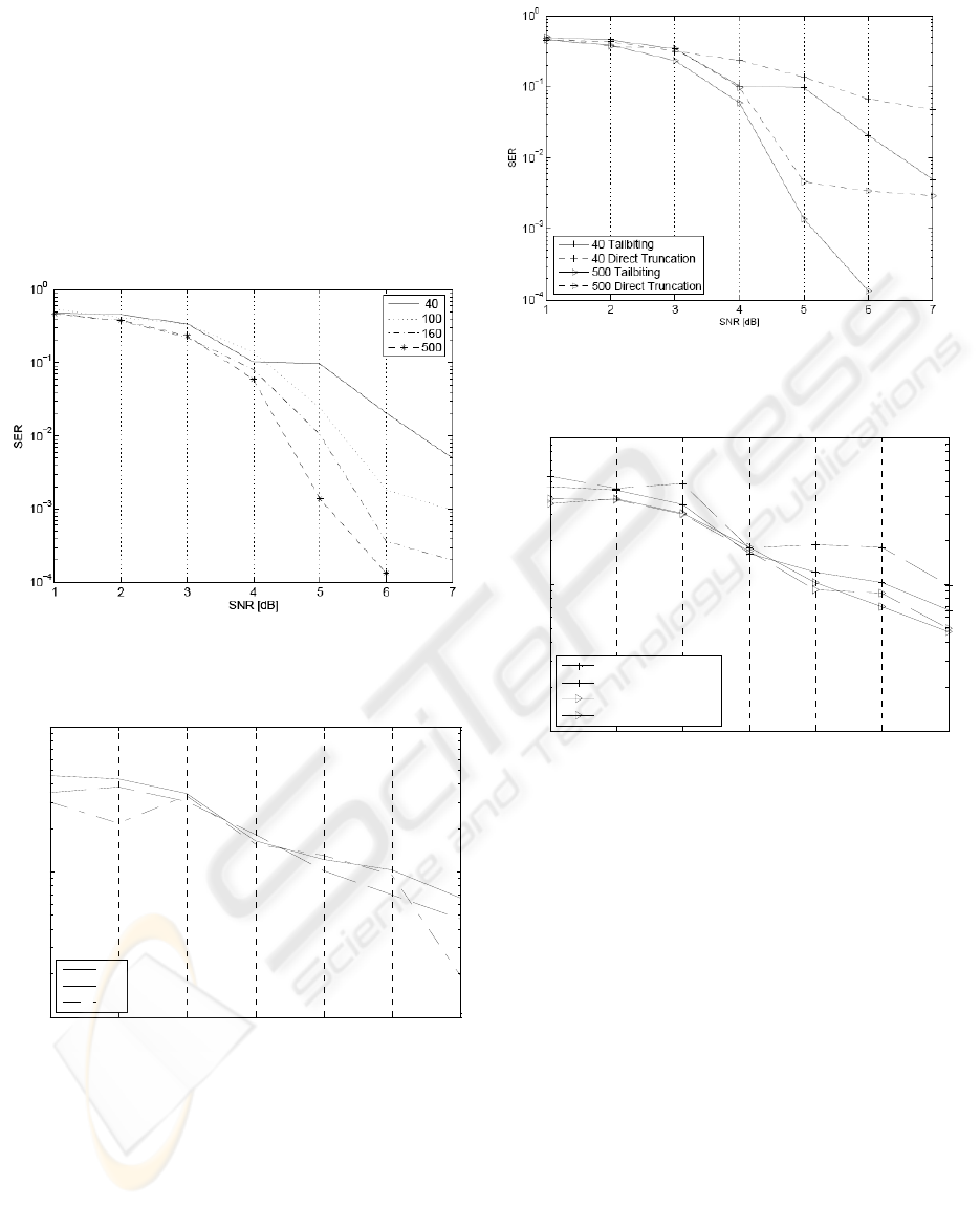
Basic performance of the turbo decoder for
symbol tailbiting over ring transmission after 6 inner
iterations with respect to the block length is showed
in Figure 7. We observe that using packet of length
500, for SER=10
-2
, it is possible to achieve a gain of
2dB with respect to the transmission with packet
size equal to 40 symbols.
At first we consider 2 transmit and 2 receive
antenna system with a fast fading channel. The
simulations were conducted for different block
lengths. As expected, the longer the block, the better
the SER.
Next simulation was made for 2 different block
lengths and for 2 different decoding techniques.
⎥
⎥
⎦
⎤
⎢
⎢
⎣
⎡
++
++
=
2
2
331
23
1)(
DD
DD
DG
TURBO SPACE TIME CODES FOR TAILBITING TRANSMISSION
143
1 2 3 4 5 6 7
10
-2
10
-1
10
0
SNR [dB]
SER
40
160
500
1 2 3 4 5 6 7
10
-2
10
-1
10
0
SNR [dB]
SER
40 Tailbiting
40 Direct truncation
160 Tailbiting
160 Direct truncation
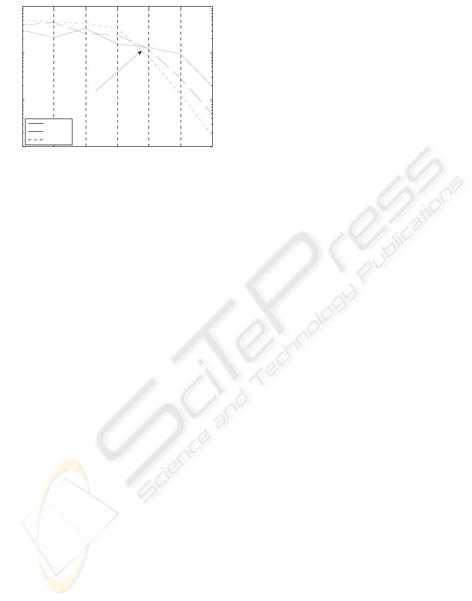
Figure 8 shows a comparison between two
decoding methods; tailbiting and direct truncation.
As expected, the later method delivers worse results.
Another important observation is that for higher
SNR, the difference between those two methods is
getting larger in favor of tailbiting. We can observe
that the tailbiting method improves the performance
about 0.3 dB for SER=10
-2
with respect to the direct
truncation method, for transmission with packet size
equal to 500.
Figure 7: Different block sizes for turbo decoder and
tailbiting trellis ending. 2TX, 2RX,
2-symbols/Hz/antennas pair, QPSK, fast fading channel.
Figure 8: Tailbiting decoding vs Direct truncation trellis
ending for 2 block sizes. 2TX, 2RX,
2-symbols/Hz/antennas pair, QPSK, fast fading channel.
For burst channels (with burst length of 130
space-time symbols), (2TX × 2RX) scenario and
different block lengths, the situation differs. As is
shown in Figure 9, the performance of the system
drops significantly.
Figure 9: Quasi-static channel (130 space symbols),
different block sizes for turbo decoder and tailbiting trellis
ending. 2TX, 2RX, 2 symbols/Hz/antennas pair, QPSK.
Figure 10: Quasi-static channel (130 space symbols),
tailbiting decoding vs direct truncation trellis ending for 2
block sizes. 2TX, 2RX, 2 symbols/Hz/antennas pair,
QPSK.
The waterfall region moved from 4 dB in fast
fading channel to 6-7 dB in quasi-static channel. For
burst channels both decoding methods, tailbiting and
direct truncation, yield almost the same performance
(still tailbiting performs better), see Figure 10.
Figure 11, shows the relation between SER and
different array sizes in a quasi-static channel for 500
block size. At 4 dB there is observable a break-
through, thus more element antenna arrays deliver
better performance. We observe that using 4TX/4RX
antennas, for SER=10
-2
, it is possible to achieve a
gain about of 0.5 dB with respect to the transmission
with 3TX/3RX antennas and the gain about of 1 dB
with respect to the system with 2TX/2RX antennas.
WINSYS 2007 - International Conference on Wireless Information Networks and Systems
144
1 2 3 4 5 6 7
10
-3
10
-2
10
-1
10
0
SNR [dB]
SER
2TX 2RX
3TX 3RX
4TX 4RX
Break-Through
Figure 11: SER performance vs different array sizes, 500
symbols block, quasistatic channel (130 space symbols),
for turbo decoder and tailbiting trellis ending.
2-symbols/Hz/antennas pair, QPSK.
7 CONCLUSIONS
New structure of Turbo space time encoder over ring
for tailbiting transmission is proposed. This paper
aimed at investigating the performance of space time
symbol interleaved non-binary turbo tailbiting coded
systems. A quasi-static and fast fading channels
were considered. In the receiver, were used iterative
soft input soft output (SOVA) algorithm.
Analysis of the obtained results shows that the
use of tailbiting coding over ring improves the
quality of the transmission in comparison to the
direct truncation method. An improvement is
observed for all packet lengths. We have to mention
that the encoding process in tailbiting method is
more complex than in direct truncation method.
REFERENCES
Vucetic, B., Yuan, J., 2003, Space-Time Coding, John
Wiley & Sons Ltd.
Ma, H.H., Wolf, J.K., 1986, On Tailbiting Convolutional
Codes. IEEE Trans. Commun., vol. 34, Feb. 1986,
104-111.
Weiß, C., Bettstetter, C., Riedel, S., 2001. Code
Construction and Decoding of Parallel Concatenated
Tail-Biting Codes. IEEE Trans. Information Theory,
Vol. 47, No.1, January 2001, 366-386.
3GPP TS 25.212 version 5.2.0 Release 5
Remlein, P., 2003. The Encoders with the feedback for the
packed transmission without tail symbols. VIII-th
Poznan Workshop on Telecommunication, PWT ’03,
Poznań 11-12 Dec. 2003, 165-169, (in polish).
Ozcelik, H., Herdin, M., Weichselberger, W., Wallace, J.,
Bonek, E., 2003. Deficiencies of ’Kronecker’ MIMO
radio channel model. Electronics Letters, 7th August
2003, vol.39, No. 16, 1209-1210.
Loyka, S., Tsoulos, G., 2002. Estimating MIMO System
Performance Using the Correlation Matrix Approach.
IEEE Communications Letters, Vol. 6, NO. 1, January
2002, 19-21.
Stefanov, A., Duman, T.M., 2001. Turbo-Coded
Modulation for Systems with Transmit and Receive
Antenna Diversity over Block Fading Channels:
System Model, Decoding Approaches, and Practical
Considerations. IEEE Journal on Selected Areas in
Communications, vol. 19, No. 5, May 2001, 958-968.
Hagenauer, J., Offer, E., Lutz, P., 1996. Iterative Decoding
of Binary Block and Convolutional Codes. IEEE
Transactions on Information Theory, Vol. 42, No. 2,
March 1996, 429-445.
Hagenauer, J., Hoeher, P., 1989. A Viterbi Algorithm with
Soft-Decision Outputs and its Applications. In Proc.
Globecom, Dallas, TX, Nov. 1989, 1680-1686.
Berrou, C., Glavieux, A., Thitimajshima, P., 1993. Near
Shannon Limit Error-Correcting Coding and
Decoding: Turbo Codes. Proc. of the 1993
International Conference on Communications, in
Proc. ICC’93, Geneva, Switzerland, May 1993, 1064–
1070.
Cong, L., Xiaofu, W., Xiaoxin, Y., 1999. On SOVA for
Nonbinary Codes. IEEE Communications Letters, Vol.
3, No. 12, December 1999, 335-337.
Cox, R.V., Sundberg, C.W., 1994. An Efficient Adaptive
Circular Viterbi Algorithm for Decoding Generalized
Tailbiting Convolutional Codes. IEEE Transactions
on Vehicular Technology, Vol. 43, No. 1, Feb. 1994,
57-68.
Massey, J. L., Mittelholzer, T., 1989. Convolutional codes
over rings. In Proc. 4th Joint Swedish-USSR Int.
Workshop Information Theory, 14 -18.
Dolinar, S., Divsalar, D., 1995. Weight distribution for
turbo codes using random and nonrandom
permutations. JPL Progress report 42-122, Aug. 15.
TURBO SPACE TIME CODES FOR TAILBITING TRANSMISSION
145
