
IMPLEMENTING
SPATIAL DATA WAREHOUSE HIERARCHIES IN
OBJECT-RELATIONAL DBMSs
Elzbieta Malinowski
∗
and Esteban Zim
´
anyi
Computer & Decision Engineering Department, Universit
´
e Libre de Bruxelles
50 av.F.D.Roosevelt, 1050 Brussels, Belgium
Keywords:
Spatial data warehouses, spatial hierarchies, implementation of spatial hierarchies.
Abstract:
Spatial Data Warehouses (SDWs) allow to analyze historical data represented in a space supporting the
decision-making process. SDW applications require a multidimensional view of data that includes dimensions
with hierarchies and facts with associated measures. In particular, hierarchies are important since traversing
them users can analyze detailed and aggregated measures. To better represent users’ requirements for SDWs,
the conceptual model with spatial support should be used. Afterwards, the conceptual schema is translated to
the logical and physical schemas. However, during the translation process the semantics can be lost. In this
paper, we present the translation of spatial hierarchies from the conceptual to physical schemas represented
in the MultiDimER model and Oracle 10g Spatial, respectively. Further, to ensure the semantic equivalence
between the conceptual and the physical schemas, integrity constraints are exemplified mainly using triggers.
1 INTRODUCTION
Data warehouses (DWs) store and provide access to
large volumes of historical data. They usually are rep-
resented as a star schema, consisting of fact and di-
mension tables. A fact table contains numeric data
called measures. Dimensions are used for explor-
ing the measures from different analysis perspectives.
They usually contain hierarchies that allow to analyze
detailed or aggregated measures using the drill-down
and roll-up operations of OLAP systems.
It is estimated that about 80% of data stored in
databases has a spatial or location component, there-
fore, the location dimension has been widely inte-
grated in DW and OLAP systems. This dimen-
sion is usually represented in an alphanumeric, non-
cartographic manner (i.e., using the place name).
Nevertheless, it is well known that the inclusion of
spatial data in the analysis process can help to reveal
patterns that are difficult to discover otherwise.
On the other hand, spatial databases (SDBs) al-
low to store and manipulate spatial objects. The latter
∗
The
work of E. Malinowski was funded by a scholar-
ship of the Cooperation Department of the Universit
´
e Libre
de Bruxelles. She is currently on leave from the Universi-
dad de Costa Rica.
correspond to real-world entities, for which the ap-
plication needs to keep their spatial characteristics.
Spatial objects consist of a thematic (or descriptive)
component and a spatial component. The former is
represented using traditional DBMS data types, e.g.,
integer, string. The spatial component includes its ge-
ometry, which can be of type point, line, surface, or
a collection of these types. Spatial objects can relate
to each other forming topological relationships (e.g.,
intersects, inside), i.e., the relationships that do not
change when spatial objects are rotated, scaled, etc.
Spatial Data Warehouses (SDWs) combine DWs
and SDBs for managing significant amounts of his-
torical data that include spatial location. To better
represent users’ requirements for SDW applications,
a conceptual multidimensional model, such as Mul-
tiDimER (Malinowski and Zim
´
anyi, 2004) should be
used. Then, the conceptual specifications are trans-
lated into the logical and physical models. How-
ever, during this translation semantics may be lost due
to the limited expressive power of current DBMSs.
Therefore, an additional programming effort is re-
quired to ensure the correctness of this translation.
In this paper, we refer to the object-relational (0R)
implementation of SDW hierarchies. As an exam-
ple of a DBMS we use Oracle 10g Spatial. We also
186
Malinowski E. and Zimányi E. (2007).
IMPLEMENTING SPATIAL DATA WAREHOUSE HIERARCHIES IN OBJECT-RELATIONAL DBMSs.
In Proceedings of the Ninth International Conference on Enterprise Information Systems - DISI, pages 186-191
DOI: 10.5220/0002355401860191
Copyright
c
SciTePress
implement integrity constraints to ensure semantic
equivalence between the conceptual and the physical
schemas. Section 2 presents works related to multidi-
mensional conceptual models with spatial elements.
Section 3 briefly describes the MultiDimER model; it
also refers to topological relationships and their im-
portance in establishing the complexity of aggrega-
tion procedures. Section 4 includes the implementa-
tion of spatial hierarchies in OR databases. Finally,
Section 5 gives the conclusions.
2 RELATED WORK
To our knowledge, very few conceptual models based
on a multidimensional view of spatial data have been
proposed. For example, (Bimonte et al., 2005) define
a spatial multidimensional model with measures and
dimensions represented as complex objects.
(Pedersen and Tryfona, 2001) extend the work of
(Pedersen et al., 2001) by inclusion of spatial mea-
sures. They focus on the problems of aggregations
in the presence of different topological relationships
existing between spatial measures.
On the other hand, (Jensen et al., 2004) extend the
model proposed by (Pedersen and Tryfona, 2001) al-
lowing to include spatial objects in hierarchies with
partial containment relationships, i.e., where only part
of spatial object belongs to a higher hierarchy level
Several authors define elements of SDWs, i.e.,
spatial measures and dimensions, e.g., (Fidalgo et al.,
2004; Rivest et al., 2001; Stefanovic et al., 2000).
Other works use SDW concepts for developing spatial
OLAP (SOLAP) systems ((Han et al., 1997; Rivest
et al., 2001; Shekhar and Chawla, 2003)).
Nevertheless, the above-mentioned authors do not
refer to implementation issues of schemas created us-
ing the conceptual models or to aspects of logical rep-
resentation of data required for SOLAP applications.
3 THE MULTIDIMER MODEL
3.1 Model Definition
The MultiDimER model (Malinowski and Zim
´
anyi,
2004; Malinowski and Zim
´
anyi, 2005) allows to rep-
resent at the conceptual level the elements required
for SDW and SOLAP applications. The description
of the model is based on the schema in Figure 1 used
for the analysis of highway maintenance costs. The
schema contains dimensions, hierarchies, a fact rela-
tionship, and measures. A dimension is an abstract
concept for grouping data that shares a common se-
mantic meaning within the domain being modeled. It
represents either a level or one or more hierarchies.
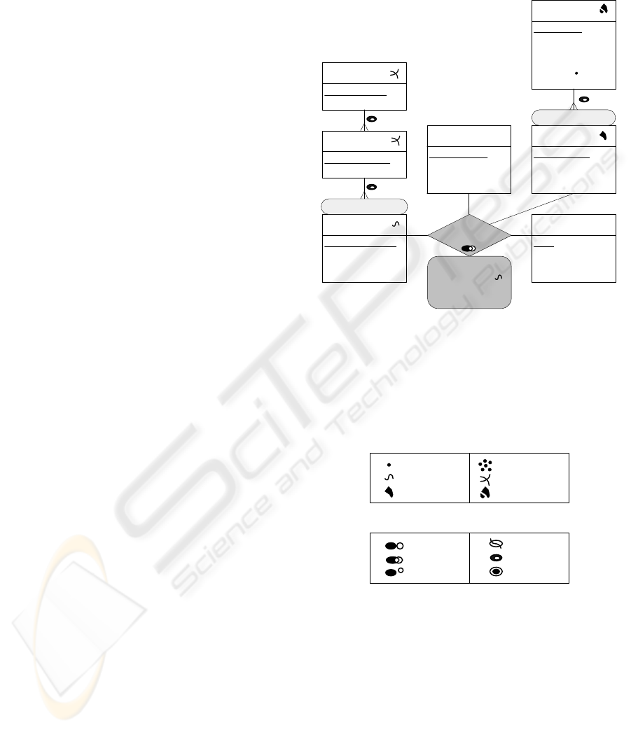
Highway
segment
Segment number
Road condition
Speed limit
...
Time
Date
Event
Season
...
Highway structure
Highway
section
Section number
...
Highway
Highway name
...
Road coating
Coating name
Coating type
Coating durability
...
County
County name
County population
County area
...
Geo location
Highway
maintenance
Length (S)
Common area
No. cars
Repair cost
State
State name
State population
State area
State major activity
Capital
...
Figure 1: An example of multidimensional schema with
spatial elements.
A level corresponds to an entity type in the ER
model and represents a set of instances called mem-
bers that have common characteristics. For example,
Road coating in Figure 1 is a one-level dimension.
Point
Line
Surface
Point bag
Line bag
Surface bag
Adjacent
Intersect
Disjoint
Cross
Within
Equal
a)
b)
Figure 2: Pictograms for a) spatial data types and b) topo-
logical relationships.
Spatial levels are levels for which the application
needs to keep their spatial characteristics. This is cap-
tured by its geometry, which in the model is repre-
sented using the pictograms shown in Figure 2 a). In
Figure 1, we have five spatial levels: County, State,
Highway segment, Highway section, and Highway.
Hierarchies are required for establishing mean-
ingful paths for the roll-up and drill-down operations.
They contain several related levels, e.g., the County
IMPLEMENTING SPATIAL DATAWAREHOUSE HIERARCHIES IN OBJECT-RELATIONAL DBMSs
187
and State levels in Figure 1. Hierarchies can express
different structures according to an analysis criterion,
e.g., geographical location. To differentiate them, the
criterion name is used, e.g., Geo location in Figure 1.
Given two consecutive levels of a hierarchy, one
is called child and the other parent depending on
whether they include more detailed or more general
data, respectively. In Figure 1, County is a child level
while State is a parent level. A level of a hierarchy
that does not have a child level is called leaf.
The relationships between child and parent lev-
els are characterized by cardinalities. In Figure 1,
the cardinality between the County and State levels
is many-to-one indicating that a county can belong to
only one state and a state can include many counties.
In a spatial hierarchy, two consecutive spatial lev-
els are related through a topological relationship. This
is represented using the pictograms of Figure 2 b).
By default the within topological relationship is con-
sidered, which indicates that the geometry of a child
member is included in the geometry of a parent mem-
ber, e.g., in Figure 1, the geometry of each county is
included in the geometry of its corresponding state.
A fact relationship (e.g., Highway maintenance
in Figure 1) represents an n-ary relationship between
leaf levels. This fact relationship can be spatial if at
least two leaf levels are spatial, e.g., the Highway seg-
ment and the County spatial levels. A spatial fact rela-
tionship may require the inclusion of a spatial predi-
cate for spatial join operations. For example, in the
figure an intersection topological relationship indi-
cates that users require to focus their analysis on those
highway segments that intersect counties.
A (spatial) fact relationship may include thematic
or spatial measures. The former are usually numeric
values that allow to perform quantitative analysis.
Spatial measures can be represented by a geometry
or calculated using spatial operators, e.g., distance,
area. The schema in Figure 1 contains two spatial
measures: Length and Common area. Length is a
number representing the length of the part of a high-
way segment that belongs to a county. Common area
represents the geometry of the common part.
3.2 Topological Constraints between
Spatial Hierarchy Levels
As was already said, in our model the default topo-
logical relationship between two consecutive spatial
levels is within. However, in real-world situations
these relationships can be different. For example, in
a spatial hierarchy formed by the Store and the City
levels, some points referring to store locations can be
on the border between two cities represented as sur-
faces. This situation may lead to the problem of mea-
sure aggregation when traversing from the Store to the
City levels since it is not clear whether the measure
(e.g., required taxes) should be distributed between
two cities or considered only for one of them.
For non-spatial hierarchies, summarizability con-
ditions were established (Lenz and Shoshani, 1997).
Summarizability refers to the correct aggregation of
measures in a higher hierarchy level (e.g., State
in Figure 1) taking into account existing aggrega-
tions in a lower hierarchy level (e.g., County in Fig-
ure 1). Nevertheless, summarizability problems may
also arise depending on the topological relationships
existing between spatial levels. Several solutions may
be applied: an extreme one is to disallow the topologi-
cal relationships that cause problems whereas another
solution is to define customized procedures for ensur-
ing correct measure aggregation.
Topological
relationship
Total containment Equal Connected
Disjoint
Related
disjoint
within
touches crosses
overlaps
equal
Forbidden
Safe aggregation
Special aggregation
procedure
Figure 3: Classification of topological relationships for ag-
gregation procedures.
In (Malinowski and Zim
´
anyi, 2005) we classi-
fied topological relationships according to the re-
quired procedures for measure aggregation. Next, we
briefly refer to this classification (Figure 3), which is
based on the intersection between the geometric union
of the spatial extents of child members (denoted by
GU(C
ext
)) and the spatial extent of their associated
parent member (denoted by P
ext
).
The disjoint topological relationship is not al-
lowed between spatial hierarchy levels since during
a roll-up operation the next hierarchy level cannot
be reached. Thus, a non-empty intersection between
GU(C
ext
) and P
ext
is required. If GU(C
ext
) within P
ext
,
then the geometric union of the child member extents
(as well as the extent of each child member) is in-
cluded in their parent member extent. In this case,
the aggregation of measures from a child to a parent
level can be done safely using a traditional approach.
Similar situation occurs if GU(C
ext
) equals P
ext
.
In the case when the topological relationships be-
tween extents of the child and parent members are
distinct from within or equal, the topological relation-
ships between the spatial extents of every individual
child member and its parent member should be re-
vised. They allow to determine which measure values
ICEIS 2007 - International Conference on Enterprise Information Systems
188

can be considered in its entirety for aggregation and
which must be partitioned.
4 IMPLEMENTATION OF
SPATIAL HIERARCHIES
Conceptual models facilitate the representation of the
semantics of the modeled reality. However, much of
this semantics may be lost when translating a con-
ceptual schema into a logical and a physical schemas
since only the concepts supported by the target DBMS
can be used. To ensure the semantic equivalence
between these schemas, integrity constraints should
be introduced. Current DBMSs provide support for
declarative integrity constraints, such as keys, ref-
erential integrity, or check constraints. However, in
many cases this support is not sufficient and integrity
constraints must be implemented using triggers. The
latter are named Event–Condition–Action rules that
are automatically activated when a table is updated.
Further, to ensure better performance during join
operations and independency from transactional sys-
tems, we choose a surrogate-based OR model. Surro-
gates are system-generated keys that cannot be seen
or modified by users. In Oracle 10g, to ensure the
existence of surrogates, an object table must be cre-
ated. It is similar to a conventional relational table
with the difference that column types correspond to
the attributes of the object type used for the table dec-
laration. Object types are types structured by users for
representing real-world objects.
Currently, several DBMSs, e.g., Oracle or In-
formix, provide extensions to define and manipulate
spatial elements. For example, Oracle 10g Spatial
allows to represent geometries using basic geomet-
ric types, such as point, line string, and polygon, or
combination of them. Oracle also extends SQL with
spatial operators and functions.
To implement spatial hierarchies, we first, refer to
spatial levels and then, to relationships between them.
4.1 Spatial Levels
In the MultiDimER model, a level corresponds to an
entity type in the ER model. Therefore, it can be
transformed to a table in the OR model. The spatial
support in the model is added in an implicit manner,
i.e., the attribute representing the geometry is repre-
sented by pictogram. Therefore, the transformation
of a spatial level into the OR representation requires
an additional attribute for representing its geometry.
The definition of a table in Oracle 10g Spatial for
representing the State level is given next. To ensure
the existence of surrogates for the State level, first a
object type must be defined:
create type StateType as object (
Geometry mdsys.sdo geometry,
Name varchar2(25), Population number(10),
Area number, MajorActivity varchar2(50),
Capital varchar2(25));
create table State of StateType (
constraint statePK primary key (Name))
object identifier is system generated;
The clause object identifier is system generated indi-
cates that a surrogate attribute is automatically gener-
ated by the system (the default option).
The OR model of Oracle Spatial provides a unique
spatial data type mdsys.sdo geometry that allows to
capture locations and shapes of spatial objects. In the
example, the attribute Geometry is used for represent-
ing the geometry of a state. The specific geometry
(e.g., point or line) is defined and instantiated during
an insert operation.
When the spatial types defined in the conceptual
schema (e.g., surface bag for the State level in Fig-
ure 1) are transformed into Oracle Spatial, the seman-
tics may be lost. This may cause that users insert a
spatial data type different from the one that is spec-
ified in the conceptual schema. Therefore, to ensure
the equivalence for spatial types between the concep-
tual and the physical schemas, a check constraint may
be suitable: alter table State add constraint ValidGeom
check (Geometry.get gtype() = 7); it enforces the ge-
ometries of a state to be of the type multipolygon
(type 7). However, Oracle does not allow such con-
structs, thus a trigger must be defined:
create or replace trigger ValidGeomState
before insert or update on State for each row
begin if :new.Geometry.get gtype() <> 7 then
raise application error(-2003,’Invalid Geometry’);
end if;
end;
4.2 Relationship between Spatial Levels
A relationship between levels forming a hierarchy
corresponds to a binary relationship in the ER model.
Therefore, this relationship can be represented in the
OR model using the traditional mapping for the bi-
nary many-to-one relationships. This requires to in-
clude in the table created for the child level an at-
tribute for representing a parent key.
Figure 1 includes the Geo location spatial hier-
archy that contains the County and the State levels.
Since we already have created a table for the State
level, next we define a table for the County level:
create type CountyType as object (
IMPLEMENTING SPATIAL DATAWAREHOUSE HIERARCHIES IN OBJECT-RELATIONAL DBMSs
189

Geometry mdsys.sdo geometry,
Name varchar2(25), Population number(10),
Area number, StateRef ref StateType);
create table County of CountyType (
StateRef NOT NULL,
constraint CountyPK primary key (Name),
constraint CountyFK foreign key (StateRef)
references State);
The CountyType object includes a reference (ref) type
that points to the corresponding row in the State ta-
ble. In this way, the OR approach replaces value-
based joins with direct access to related rows using
the identifiers. Further, not allowing the attribute
StateRef to have null values and enforcing referential
integrity constrains ensure that every county member
has assigned a valid state member. However, to in-
sert data into the County table, the surrogates of the
corresponding state members should be known. To
facilitate this operation we create a view allowing to
introduce a state name instead of a state surrogate:
create view CountyView (Geometry, Name,
Population, Area, StateName) as
select C.Geometry, C.Name,
C.Population, C.Area, S.Name
from County C, State S
where C.StateRef = ref(S);
Since views defined on two tables cannot be up-
dated, to insert data into the County table using the
CountyView, an instead of trigger should be created;
it performs actions instead of the operation specified
in the trigger.
Further, topological relationships between spatial
levels forming a hierarchy should also be considered
during implementation for preventing the inclusion of
incorrect data and for indicating what kind of aggre-
gation procedures should be developed. Two solu-
tions can be proposed: (1) constraint the geometry of
the child member during the insert operation or (2)
verify topological relationships between the geomet-
ric union of the spatial extents of child members and
the spatial extent of their associated parent member,
after the insertion of all child members.
The first solution requires the verification of the
topological relationship between spatial extents of a
county and a state members:
create or replace trigger CountySpaIns instead of
insert on CountySpaView for each row
declare StGeometry State.Geometry%Type;
begin select S.Geometry into StGeometry
from State S where S.Name = :new.StateName;
if SQL%found then
if sdo geom.relate(StGeometry,’anyinteract’,
:new.Geometry,0.005) = ’TRUE’ then
insert into County select :new.Geometry,
:new.Name, :new.Population; :new.Area, ref(S)
from State S where S.name = :new.StateName;
else raise application error(-2002, ’Invalid
Top. Rel.’); end if;
else raise raise application error(-2000,
’Invalid State Name: ’ || :new.StateName); end if;
end;
The trigger raises errors if the state name is invalid or
if the geometry of a county member is disjoint from
the geometry of its corresponding state member. Oth-
erwise, it inserts the new data into the County table.
In the example, to check topological relationships we
use the sdo geom.relate function with an ’anyinteract’
mask, which accepts any topological relationships but
disjoint between child and parent members. However,
a specific topological relationship can be used instead
of anyinteract, e.g., covers.
In the second solution we allow to include child
members without activating an instead of trigger. Af-
ter all child members are inserted, the verification
of the topological relationship between the geomet-
ric union of the spatial extents of child members and
the spatial extent of their associated parent member is
performed. An example of this verification is given
next. First, we define a function that receives a state
name and returns 1 if the spatial extent of a given
State member is equal to the geometric union of the
spatial extents of its County members:
create or replace function ChildrenWithinParent
(StateName State.Name%Type) return Number is
StName State.Name%type;
begin select S1.Name into StName
from State S1, (select S2.Name as SName,
sdo aggr union(sdoaggrtype(C.Geometry, 0.005))
as Geometry from County C , State S2
where C.StateRef = ref(S2)
group by S2.Name ) GU
where S1.Name = StateName and GU.SName =
S1.Name and sdo geom.relate(S1.Geometry, ’equal’,
GU.Geometry, 0.005)= ’equal’;
if SQL%found then return 1; else return 0; end if;
end;
We use the sdo aggr union function, which returns a
spatial object represented as the geometric union of
the specified spatial objects, e.g., county members.
This function works similarly to the aggregate func-
tions used for non-spatial data, i.e., when the group by
clause is included and the specific function is selected
(e.g., sum) with the difference that it refers to spatial
data. The select statement in the from clause, creates
a temporary table GU with two attributes SName and
Geometry. The latter is the geometric union of coun-
ties grouped by a state name. Then, this table is used
in the second
where
statement for testing the
equal
ICEIS 2007 - International Conference on Enterprise Information Systems
190

topological relationship.
The ChildrenWithinParent function can be called
for a specific state or for all states. Next, we show an
example of this call displaying a message instead of
taking some specific action:
declare StName State.Name%type;
cursor RetrieveState is
select S.Name from State S;
begin open RetrieveState;
loop fetch RetrieveState into StName;
exit when RetrieveState%notfound;
if (ChildrenWithinParent (StName) = 1) then
dbms output.put line(StName ||
’ is totally covered by its counties’);
else dbms output.put line(StName ||
’ is not totally covered by its counties’);
end if; end loop;
close RetrieveState;
end;
Since the branch else indicates that some (or all)
counties intersect their state member
2
, we must
check the topological relationships of individual child
members. These topological relationships can be
easily retrieved in Oracle using, e.g., the follow-
ing function for a state member S in the State
table and every related child member C in the
County table: sdo geom.relate(S.Geometry, ’deter-
mine’, C.Geometry, 0.005). Based on that and accord-
ing to user requirements, an appropriate aggregation
procedure can be developed.
5 CONCLUSIONS
The MultiDimER model provides the multidimen-
sional view of data and allows spatial support in lev-
els, hierarchies, fact relationships, and measures. In
particular, spatial hierarchies are important since they
allow to see detailed and aggregated measures while
traversing different levels. However, to ensure cor-
rect measure aggregation, topological relationships
between spatial hierarchy levels must be considered.
Furthermore, even though the model captures
users’ requirements for SDW applications, the result-
ing conceptual schemas must be translated to specific
implementation platforms (DBMSs). However, the
semantics can be lost during this translation process
due to limited expression power of current DBMSs.
This paper presented a transformation of spatial
hierarchies to the OR implementation model using as
an example Oracle 10g with its spatial extension. We
2
In a real situation, counties are included in states, i.e.,
this topological relationship is equal, however we use the
same example to shorten the paper’s size.
also referred to integrity constraints that allow to pre-
serve the semantics of a more expressive conceptual
schema while transforming to a physical schema.
The proposed mappings to the OR model along
with the examples using a commercial system, show
the applicability of the given solutions in real-world
situations and the feasibility of implementing SDWs
in current commercial DBMSs.
REFERENCES
Bimonte, S., Tchounikine, A., and Miquel, M. (2005). To-
wards a spatial multidimensional model. In Proc. of
the 8th ACM Int. Workshop on Data Warehousing and
OLAP, pages 39–46.
Fidalgo, R., Times, V., Silva, J., and Souza, F. (2004).
GeoDWFrame: A framework for guiding the design
of geographical dimensional schemes. In Proc. of the
6th Int Conf. on Data Warehousing and Knowledge
Discovery, pages 26–37.
Han, J., Koperski, K., and Stefanovic, N. (1997). Ge-
oMiner: a system prototype for spatial data mining.
In Proc. of the ACM SIGMOD Int. Conf. on Manage-
ment of Data, pages 553–556.
Jensen, C., Klygis, A., Pedersen, T., and Timko, I. (2004).
Multidimensional data modeling for location-based
services. VLDB Journal, 13(1):1–21.
Lenz, H. and Shoshani, A. (1997). Summarizability in
OLAP and statistical databases. In Proc. of the 9th
Int. Conf. on Scientific and Statistical Database Man-
agement, pages 132–143.
Malinowski, E. and Zim
´
anyi, E. (2004). Representing spa-
tiality in a conceptual multidimensional model. In
Proc. of the 12th ACM Symposium on Advances in Ge-
ographic Information Systems, pages 12–21.
Malinowski, E. and Zim
´
anyi, E. (2005). Spatial hierar-
chies and topological relationships in the Spatial Mul-
tiDimER model. In Proc. of the 22nd British Nat.
Conf. on Databases, pages 17–28.
Pedersen, T., Jensen, C., and Dyreson., C. (2001). A foun-
dation for capturing and querying complex multidi-
mensional data. Information Systems, 26(5):383–423.
Pedersen, T. and Tryfona, N. (2001). Pre-aggregation in
spatial data warehouses. In Proc. of the 7th Int.
Symposium on Advances in Spatial and Temporal
Databases, pages 460–478.
Rivest, S., B
´
edard, Y., and Marchand, P. (2001). Toward
better suppport for spatial decision making: Defin-
ing the characteristics of spatial on-line analytical pro-
cessing (SOLAP). Geomatica, 55(4):539–555.
Shekhar, S. and Chawla, S. (2003). Spatial Databases: A
Tour. Prentice Hall.
Stefanovic, N., Han, J., and Koperski, K. (2000). Object-
based selective materialization for efficient implemen-
tation of spatial data cubes. TKDE, 12(6):938–958.
IMPLEMENTING SPATIAL DATAWAREHOUSE HIERARCHIES IN OBJECT-RELATIONAL DBMSs
191
