
EML:A TREE OVERLAY-BASED VISUAL LANGUAGE FOR
BUSINESS PROCESS MODELLING
Lei Li and John Hosking
Department of Computer Science
University of Auckland, Auckland, New Zealand
John Grundy
Department of Computer Science and Department of Electrical and Computer Engineering
University of Auckland, Auckland, New Zealand
Keywords: Modelling Languages, Visual Notation, Business Process Modelling.
Abstract: Visual business process modelling can fulfil an important role to enable high-level specification of system
interactions, improve system integration and support performance analysis. Existing modelling approaches
typically use a workflow based method. Cobweb and labyrinth problems appear quickly when this type of
notation is used to model a complex enterprise system with users having to deal with either very complex
diagrams or many cross-diagram implicit relationships. In contrast, a tree based presentation can be very
efficient for handling visual relationships. We present an overview of EML (Enterprise Modelling
Language), a novel tree overlay-based visual specification for enterprise process modelling and its support
tool. The highlight is its flexibility in modelling business processes using different layers. A service-
oriented tree structure represents the system functional architecture. Business process modelling is
constructed as an overlay on top of this service tree. By using a multi-layer structure, an enterprise system
can be modelled with a variety of early aspects to satisfy design requirements. An Eclipse based software
tool, MaramaEML has been developed to edit EML diagrams integrated with existing modelling languages
such as BPMN and supports automatic generation of BPEL code.
1 INTRODUCTION
Since the early 1970s many languages, standards,
methodologies and tools for enterprise modelling
have been created. Examples include Entity-
relationship models (Chen. 2002), Data Flow
Diagrams, Flow Charts (Urbas, Nekarsova and
Leuchter 2005), Scenarios, Use Cases, and
Integration Definition for Functional and workflow
Modelling (Eriksson and Penker, 2000).
The Unified Modelling Language (UML) is used
to specify enterprise systems using the Model
Driven (Marshall 2000) and business patterns
approaches (Eriksson and Penker, 2000). UML 2.0
Activity Diagrams (Schnieders and Puhlmann 2005)
provide additional modelling elements that make
them more expressive than UML 1.0. BPMN (BPMI
2006) is a new process modelling language that
allows definition of business processes in
diagrammatic form. It aims to abstract away
technical details in order to be understood by both IT
and business people. Many new tools have adopted
BPMN’s box and line notation to represent
enterprise system processes. ARIS (Scheer 1996) is
a process modelling and analysis method. It
represents a holistic view of process design,
management, workflow, and application processes
based on Event-Driven Process Chains. The form-
based enterprise method (Draheim and Weber, 2005)
analyses the whole enterprise system in a form-
based style to achieve an optimized modelling
framework for the system. BioOpera (Pautasso
2005) is a workflow based visual process language
for service composition. It has conditional
execution, failure handling, optional safety, iteration,
nesting and recursion features. JOpera, its support
tool, offers an autonomic execution platform for
building distributed systems using the graphical
editing framework (Pautasso 2005). Web Transition
131
Li L., Hosking J. and Grundy J. (2007).
EML:A TREE OVERLAY-BASED VISUAL LANGUAGE FOR BUSINESS PROCESS MODELLING.
In Proceedings of the Ninth International Conference on Enterprise Information Systems - ISAS, pages 131-137
DOI: 10.5220/0002366301310137
Copyright
c
SciTePress

Diagrams (WTD) and T-Web systems (Kornkamol,
Tetsuya and Takehiro 2003) automate construction
of web applications/web services from templates.
ZenFlow (Martinez etc 2005) is a visual composition
tool for web services written in BPEL4WS. It
provides visual facilities to ease process definition.
More recently, a young but rapidly growing research
field, aspect-oriented modelling (AOM), has been
recognized as valuable for dealing with crosscutting
concerns at early stage software development
(Gokhale and Gray 2005). This approach analyses a
complex system from multiple viewpoints to
identify abstract components. Most Enterprise visual
modelling languages adopt box-and-line style
diagrams. These generally work well for small to
medium diagrams.
However, a common source of difficulty in all of
these approaches is an appropriate visual method to
reduce the complexity of large business modelling
diagrams. Most existing modelling technologies are
effective in only limited problem domains or have
major weaknesses when attempting to scale to large
systems modelling e.g. “cobweb” and “labyrinth”
problems (Guerra et al 2005). Multi-view tool
support and multi-level structure approaches have
been applied to mitigate this problem (Schnieders et
al, 2005; Zhu et al, 2004). These approaches have
achieved some success but cannot fully solve the
problem, because using the same notation and flow
method in a multi-view environment just reduces
individual diagram complexity, but increases hidden
dependencies. (Erkisson 2000; Grundy et al, 2006).
It requires long term memory of the users, as they
have to build and retain the mappings between views
mentally. In addition, most existing flow based
business modelling notations lack multiple levels of
abstraction support.
In contrast, using a tree structure is an efficient
way of representing the hierarchical nature of
complex systems graphically (Li et al, 2004; Phillips
1995). Trees also support navigation, elision and
automatic layout in ways difficult to achieve with
graph-based approaches. We have designed EML, a
novel tree overlay-based visual notation and its
integrated support environment to supplement and
integrate with existing enterprise level modelling
solutions. The study in this paper aims to address
two main research questions:
• whether it is valuable to use EML’s novel tree
structure-based visual modelling language as a
supplement to overcome the shortcomings of
existing business process notations.; and
• whether EML models of complex business
processes effectively reduce presentation
complexity.
2 ENTERPRISE MODELLING
LANGUAGE
Given the discussion in section 1, we designed EML
and its integrated tool to address the visual and
business limitations of existing modelling languages
and their support tools. Our approach does not
exclude existing modelling notations. We aim to
incorporate them into our EML support tool while
providing additional richer, integrative views for
enterprise process modelling. Indeed, our
MaramaEML support tool includes several BPMN,
UML and Form Chart views.
2.1 Tree Structure
EML uses a tree layout to represent the basic
structure of a service. We chose to use trees as they
are familiar abstractions for managing complex
hierarchical data for business modellers and business
people; can be easily collapsed and expanded to
provide scalability; can be rapidly navigated; and
can be over-laid by cross-cutting flows and concern
representations. Earlier work on modelling complex
user interfaces and their behaviour with tree-based
overlays demonstrated these benefits (Li et al, 2004).
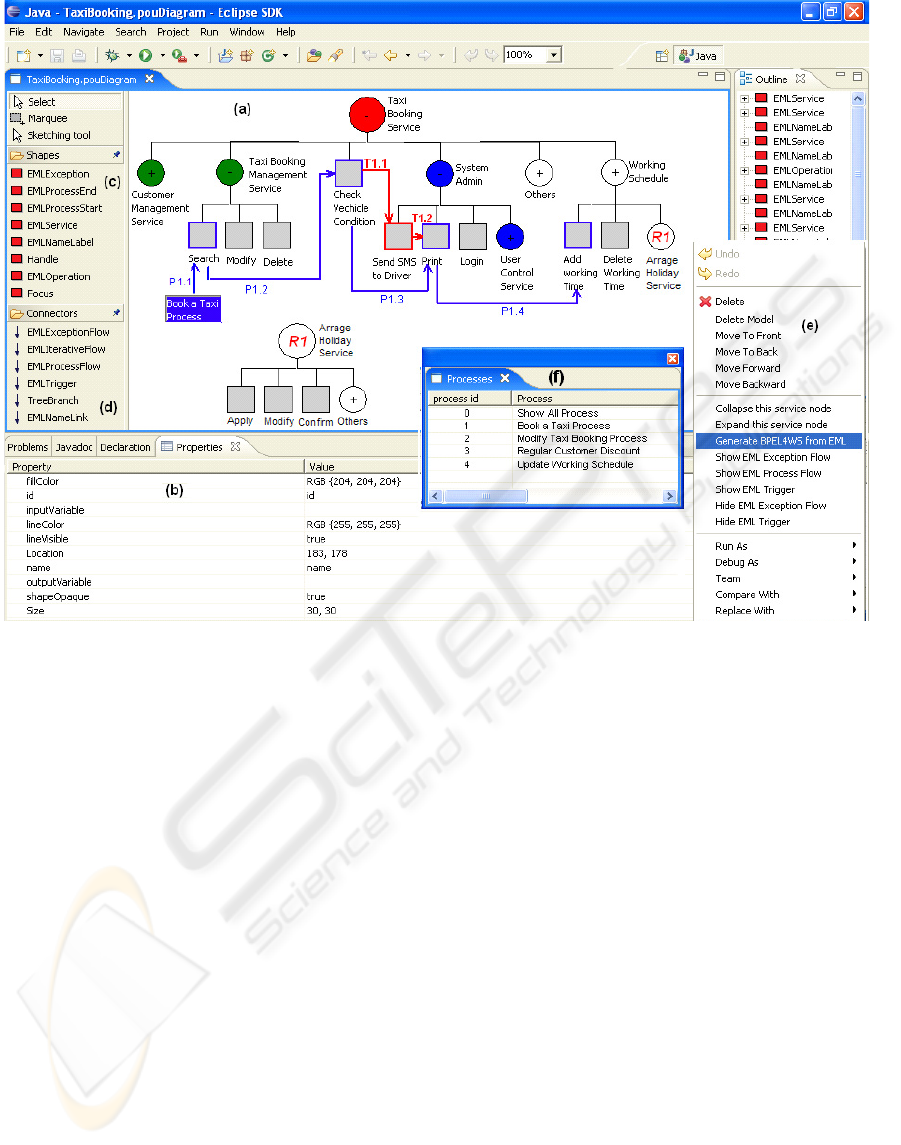
Figure 1 (a) shows a simple example of an EML
tree structure modelling a composite taxi booking
service. The customer management, taxi
management, system admin and working schedule
services are sub-services (represented as ovals) of
the taxi booking service. The system admin service
also includes an embedded user control service. The
rectangle shapes represent atomic operations inside
the service. In an EML-modelled enterprise system,
major services are represented as separate trees.
Symbols inside each service are used to identify
the elision level of the service visualisation. A minus
symbol indicates all activities in the service have
been expanded (e.g. Taxi Booking Management
Service, System Admin Service). A plus indicates
that part or all of the sub-tasks (services) are elided
(e.g. Customer Management Service, Other Service).
Every notation in the diagram has elide and expand
attributes to give the users freedom to control the
size of the diagram via elision of selected parts.
Each element in the tree has a list of associated
properties (in Figure 1 (b)). For example, service
properties include service type, status, input, output,
loop, condition, rule etc. By setting these properties,
EML users can specify detailed levels of design in
stages catering to different modelling needs.
ICEIS 2007 - International Conference on Enterprise Information Systems
132
2.2 Process Flow
Each business process is represented as an overlay
on the basic tree structure or an orchestration
between different service trees. In a process layer,
users have the choice to display a single process or
collaboration of multiple processes. By modelling a
business process as an overlay on the service tree
structure, the designer is given a clear overview of
both the system architecture and the process at the
same time. Processes can be elided mitigating the
cobweb problem common in existing flow based
visual notations.
P1.1 to P1.4 in Figure 1 (a) shows the Book a
Taxi process on the Taxi Booking Service tree. The
process starts with a process name followed by a
process flow (blue arrow) to represent the sequence.
Each flow has a sequence number, for a complex
process, the user can use this number to represent
concurrency / synchronization. The outline borders
of involved operations or services become bold to
identify the track. Data is bound to a process flow to
feed in or out of the operations. In this process, the
operator uses the Search Booking operation to check
the taxi booking record. When a suitable record is
found, the vehicle’s working condition is checked,
and the booking confirmed. Detailed booking
information is printed and added to taxi driver’s
working schedule.
2.3 Dependency / Internal Exception
It is important to know if a specific event occurs or
condition met. Events and conditions are referred to
as dependency relationships. In some cases, we can
also treat internal (system) exceptions as triggers.
An EML trigger layer can be used to solve
dependency problems. T1.1 to T1.2 in Figure 1 (a)
shows how dependency information can be passed
from one part of a process to another if a normal
process flow is insufficient.
The Book a Taxi process (P1.1~P1.4) starts with
an invocation of the Search operation. If the system
finds a record, it checks the vehicle’s working
condition and then prints the booking and adds it to
the schedule. In this process, the system also needs
to send an SMS message to inform the driver of the
Figure 1: Using MaramaEML to Create Book a Taxi Process.
EML: A TREE OVERLAY-BASED VISUAL LANGUAGE FOR BUSINESS PROCESS MODELLING
133

vehicle checking result. However this operation is
not executed until after the Check Vehicle Condition
operation is completed. The red single arrowhead
trigger connector (T1.1~T1.2) represents the
dependency. The user can define the trigger
conditions as attributes at both ends of the connecter
to control the dependency situation. The start and
end point of a trigger can be a service, operation or
process. Since EML uses a multi-layer structure,
users can choose to combine the trigger layer with
the process layer (as in figure 1) or separate them by
using different views to reduce diagram complexity.
2.4 Reuse
An EML reusable component is represented in a
separate tree. The user pre-defines its structure and
saves it in the library. Reusable components have a
unique name for future usage. The user can easily
attach a reusable component to any branch of an
EML tree. Figure 1 (a) shows a Arrange Holiday
Service has been reused in a Taxi Booking Service.
The unique service name “R1” (in the middle of
service notation) indicates it as a reusable service.
2.5 Iteration
EML supports specification of process iteration at
different levels. A single activity loop is represented
as a dashed outline border (Figure 2(a)). Attributes
control the iteration (e.g. loop times, start and
complete conditions, input/output data etc.). Loops
of two operations, use a dashed line with two
arrowheads. Figure 2(b) shows iteration of the
Search Booking and Modify Booking operations. The
process loops until a termination condition is met.
Figure 2(c) shows a loop involving three operations.
A single arrowhead dashed line guides direction,
linking different operations or services in a closed
circuit. In all three situations, the designer can set
loop start and end conditions as iteration properties.
2.6 Exception Handling
The exception overlay in EML is used to model
transaction errors. A failure handling notation (a
green question mark in the middle of each operation
or service) is used to specify/annotate a transaction
failure. The user can set up a start condition to
discriminate different kinds of failures and activate
an appropriate exception handler. An exception
handling layer is constructed to model transaction
error handling in detail. This differs from the process
flow and trigger layers but users can combine them
to generate an integrated view of the whole
processor separate them to show individual parts.
Figure 3 represents a taxi confirm booking
process with two different exception handlers
overlaid. When the user checks the vehicle
condition, an error handler is added to the operation
(a green question mark in the Check Vehicle
Condition square). A diamond shape (attached at the
boundary of the Check Vehicle Condition square) is
used to express the condition flows. If the vehicle
cannot pass the condition check (Fail), it will Delete
the booking and drive the exception handler to carry
out an alternative process. In this figure, such a
process is defined in another layer. The designer can
only see an exception handler icon in this process
view.
If the vehicle Passes the checking, the system
will then Add Working Time. A second exception
hander is added to the Add Working Time operation.
Here, if all taxi drivers are busy at the required time
a booking cannot be taken. The alternative
transaction is to negotiate with the customer for an
alternative booking. Two green arrowhead
connectors (E1.1~E1.2) represent the exception
flow. The border of operations and services are
green to track the sequence. Symbol C1 is an
annotation used to describe the flow execution
condition. Here, it may be a reference to the process
name in a policy manual. At the end of this
exception flow, it links to the start point of the
process to repeat the previous process again after the
booking time changes. The second transaction flow
is integrated into the process flow allowing users to
obtain a more systemic overview.
3 MARAMA-EML
We have developed an integrated design
environment (MaramaEML) for creating EML
specifications. MaramaEML aims to provide a
platform for efficiently producing EML visual
models and to facilitate their creation, display,
editing, storage, code generation and integration
with other diagrams. We have used the MVC pattern
to implement this tool (Buschmann and Meunier etc.
1996). MaramaEML is implemented using our
Marama meta-tool (Grundy et al 2006) as a set of
Eclipse plug-ins, providing a robust and scalable
design tool. MaramaEML provides a good basis to
enhance the integration and generation ability of
different notations. The tool supports close
integration with UML, BPEL, 3
rd
party model
ICEIS 2007 - International Conference on Enterprise Information Systems
134
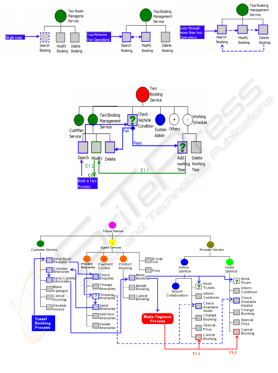
Figure 2: Different Loops in EML
(
c
)
(a)
(b)
(c)
Figure 3: Exception Handler.
Fi
g
ure 4: Travel Bookin
g
Process.
Figure 2: Different Loops in EML.
EML: A TREE OVERLAY-BASED VISUAL LANGUAGE FOR BUSINESS PROCESS MODELLING
135

analysis and coding tools via Eclipse models. By
using generated XML-based BPEL scripts as an
interchange format a single notation can be
integrated effectively with other modelling
technologies. This integration approach provides
multi-level framework support for flexible and broad
integration of complex enterprise system models.
Figure 1 shows a screen dump of a
MaramaEML model in use with a typical EML tree
with a process overlay. The user produces a Book a
Taxi process in Figure 1 (a) using the MaramaEML
modeling diagram tools. To the left of the EML
diagram area are the MaramaEML shapes (c) and
connectors (d) toolbars. This provides options
relating directly to the construction and editing of
EML tree in the central work area (a). The EML
process layer is then compiled to BPEL4WS
executable code via code generation handler in (e).
Code is generated by model dependency analysis
and translation to structured activity constructs.
MaramaEML aims to provide a platform for the
efficient production and navigation of EML. The
tool supports a drag and drop approach and any parts
of an EML tree can be directly selected and moved.
Elision and expansion are triggered via popup menu
(e). Collapse this service node and Expand this
service node functions are available for the user to
elide or expand a service node. The user can also
select Show/Hide EML Process/Exception/Trigger
Flow functions to view or hide overlays. When a
Show/Hide Flow function is selected, a detailed flow
list is brought to the screen for further selection.
Figure1 (f) shows the detailed Process List when the
user selects the Show EML Process Flow function.
By double clicking the process names in this list, the
user can select to view one (or more) appointed
process or all of them. Similar operation applies to
the Exception and Trigger Flows.
4 CASE STUDY
Figure 4 shows a Travel Booking Process in an EML
process overlay. Only process related services and
operations are shown; other, unrelated services have
been elided (e.g. Payment Control Service, Airport
Collaboration Service). The process starts (left
rectangle) with a client side application passing a
request message to the Send Book Request operation
of the Customer Service. The Agent Service receives
the request through the Check Enquires function,
and uses its Request Itineraries operation to check
availability information with the Airline and Hotel
services. The agent requests flights and rooms with
a list of parameters. There are iterations (dashed
double arrowheads links) between Request
Itineraries, Check Available Seats and Check
Available Rooms. When the agent finds that both
the air ticket and the hotel room are available on the
requested date, it terminates the loop and sends the
client a report generated by the Send Itineraries
operation. The customer Considers Itineraries and
Sends Confirm Information to the Agent Service.
The agent receives this information and then Makes
Booking. After both Book Tickets and Book Room
operations are successfully completed, the agent
calls Make Payment Process to ask the for payment
and end the existing process (Rounded Rectangle).
The process also includes exceptions and
triggers to handle transaction failures. These are
defined in different layers to keep the process
diagram clear and simple but can be integrated in the
same place for a comprehensive overview if
required. Figure 4 does include a trigger flow (T1.1
and T1.2) and an exception icon (question mark) in
the process layer to demonstrate basic integration.
The trigger flow specifies that if the agent doesn’t
receive the payment in ten days (condition defined
in flow property), it will automatically cancel the
booking. In an enterprise system, the designer
usually needs more than one transaction to handle an
exception. In the above, we can encapsulate all
transactions as a single icon in the process view (e.g.
in Book Ticket, Book Room & Request Itineraries),
and model them using detailed exception flows.
5 DISCUSSION
To the best of our knowledge, EML is the first tree
overlay structure visual language in the area of
business process modeling. Service architectures are
represented as trees and business sequences are
modelled as process overlays on the service trees.
By combining these two mechanisms EML gives
users a clear overview of an enterprise system
structure while business processes are modelled by
overlays on the same view. EML uses a multi layer
structure to model business processes, exception
handlers and dependency triggers in different levels.
This approach significantly reduces the complexity
of business processes.
There are some limitations in our approach.
Firstly its empirical base is still somewhat limited as
we have only applied EML to seven substantial case
studies. However, despite this small number, our
results are encouraging. Second, no formal usability
evaluation has been applied to the MaramaEML
tool. Hence, we are aware that tool usability and
efficiency will need further iteration.
ICEIS 2007 - International Conference on Enterprise Information Systems
136

REFERENCES
BPMI.. 2006. http://www.ebpml.org/bpml.htm
Buschmann, F., Meunier, R., Rohnert, H., 1996. Pattern-
Oriented Software Architecture. John Wiley and Sons.
Chen, P., 2002. Entity-relationship modeling
Contributions to SE, p296 ~ p310, Springer-Verlag,
NY
Draheim, D., Weber, G., 2005. Form-Oriented Analysis,
Springer-Verlag Berlin Heidelberg
Eriksson, H.E., Penker, M., 2000. Business modeling with
UML: business patterns at work, Wiley
Gokhale, A., Gray, J., 2005. An Integrated AOMD
Development Toolsuite for Distributed Real-Time and
Embedded Systems, Proc 6
th
I W- AOM, Chicago
Grundy, J.C., Hosking, J.G., Zhu, N., Liu, N., 2006.
Generating Domain-Specific Visual Language Editors
from High-level Tool Specifications, Proc ASE06
Japan
Guerra, E., Diaz P., Lara J., 2005. A Formal Approach to
the Generation of Visual Language Environments
Supporting Multiple Views, Proc VL/HCC'05, Dallas,
TX, p284 ~ p286
Kornkamol, J., Tetsuya S., Takehiro T., 2003. A Visual
Approach to Development of WS
Providers/Requestors, Proc of VL/HCC'03 pp. 251-
253, Auckland
Li, L., Phillips, C.H.E., Scogings C.J., 2004. Automatic
Generation of a Graphical Dialogue Model from
Delphi, Proc of APCHI 2004, Rotorua, p221~p230
Martinez, A, Patino.M. M, Jimenez.P. R., 2005. ZenFlow:
A Visual Web Service Composition Tool for
BPEL4WS, Proc VL/HCC'05, Dallas, TX
Marshall, C., 2000. Enterprise Modeling with UML.
Designing Successful Software Through Business
Analysis, Addison Wesley
Pautasso, C., 2005. JOpera: an Agile Environment for
Web Service Composition with Visual Unit Testing,
Proc of VL/HCC'05, Dallas, p311 ~ p313
Phillips, C.H.E., 1995. Lean Cuisine+, An Executable
Graphical Notation for Describing Direct
Manipulation Interfaces, Interacting with Computers,
7,1, p49~p71
Scheer, A.W., 1996. ‘ARIS-Toolset:Von Forschungs-
Prototypen zum Produkt’ Informatik-Spektrum 19: 71–
78, Springer-Verlag
Schnieders, A., Puhlmann, F., 2005. Activity Diagram
Inheritance. In Proc of the 8th ICBIS, Poland, p3 ~
p15
Urbas. L., Nekarsova. L., Leuchter. S., 2005. State chart
visualization of the control flow within an ACT-R/PM
user model, In Proc. IWTMD05, p43~p48.
Zhu, N., Grundy, J.C., Hosking, J.G., 2004. Pounamu: a
meta-tool for multi-view visual language environment
construction, Proc VL/HCC’04, Rome, p254 ~ p256
EML: A TREE OVERLAY-BASED VISUAL LANGUAGE FOR BUSINESS PROCESS MODELLING
137
