EXTENDING BUSINESS PROCESS MODELING TOOLS WITH
WORKFLOW PATTERN REUSE
Lucinéia Heloisa Thom
1
, Jean Michel Lau
1
, Cirano Iochpe
1,2
and Jan Mendling
3
1
Institute of Informatics, Federal University of Rio Grande do Sul, Av. Bento Gonçalves, 9500, Porto Alegre, RS, Brazil
2
Information and Communication Technology Company of Porto Alegre, Av. Ipiranga, 1200, Porto Alegre, RS, Brazil
3
Institute of Information Systems and New Media, Vienna University of Economics, 1090 Vienna, Austria
Keywords: Business process modeling, workflow patterns, event driven process chains, reuse.
Abstract: For their reuse advantages, workflow patterns are increasingly attracting the interest of both researchers and
vendors. However, actual workflow modeling tools do not provide functionalities that enable users to de-
fine, query, and reuse workflow patterns properly. In this paper we gather a set of requirements for process
modeling tools that aim to support pattern reuse in a direct way. In order to demonstrate the feasibility of
these requirements we present a respective implementation project that extends the process modeling tool
EPC Tools with pattern reuse functionality.
1 INTRODUCTION
Business Processes and respective workflow models
frequently include a variety of fragments (or recur-
rent business functions) which can be understood as
self-contained activity blocks with a specific and
well-defined semantics (Thom, 2006). As an exam-
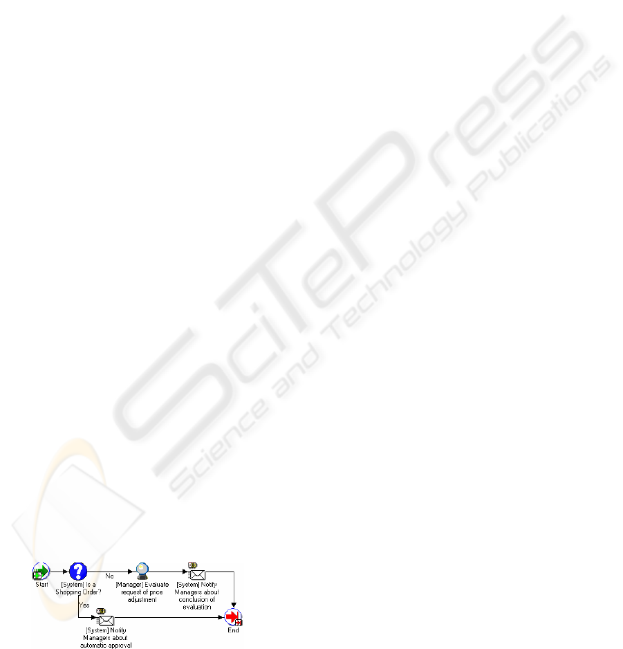
ple consider the evaluation process for price adjust-
ment as depicted in Figure 1. This process includes
activities with the following partial order: (a) is a
shopping order or not; (b) evaluate request of price
adjustment; (c) notify managers about conclusion of
evaluation; (d) notify managers about automatic
approval. Altogether this process comprises frag-
ments having generic semantics that can be de-
scribed as a pattern such as decision (activity a),
notification (activities c and d), and task execution
request (activities b). In this paper, we are dealing
with the question of how the modeling of processes
that include recurrent business functions like notifi-
cation in Figure 1 can be supported appropriately by
a tool.
Figure 1: Evaluation process for price adjustment.
So far, several workflow patterns have been sug-
gested for representing control flow (Aalst, 2002),
data (Russell, 2005), resources (Russell, 2004), in-
teraction (Bradshaw, 2005) and exception handling
(Russell, 2006). Yet, these pattern sets have in
common that they are relevant for the implementa-
tion of a workflow system and the definition of
process modeling languages, but they provide only a
partial answer to the question of what business func-
tions a modeler has to consider repeatedly in various
process models. Usually, such process fragments
(Flores, 1988), (Medina-Mora, 1992), (Malone,
2004), (Muehlen, 2002), (Bradshaw, 2005) are re-
designed for practically every workflow application.
Such a procedure can be considered as inefficient,
and thus undesirable from a maintenance perspec-
tive. While there is some research reported on how
metadata can be organized to manage large-scale
modeling project (see Thomas and Scheer 2006), we
are not aware of any work evidencing the existence
of recurrent patterns in real workflow applications as
well as their necessity and completeness for the
business and workflow process modeling. Beyond
that, contemporary workflow modeling tools do not
provide functionalities that enable users to define,
query, and reuse such patterns in a proper way.
Related to these problems we proposed a set of
nine workflow patterns in an early work (Thom,
2006). Each pattern represents a recurrent business
function (such as the ones showed in Figure 1) fre-
quently found in business processes. In this paper we
present a set of requirements related to reuse of these
patterns in business process and workflow modeling
447
Heloisa Thom L., Michel Lau J., Iochpe C. and Mendling J. (2007).
EXTENDING BUSINESS PROCESS MODELING TOOLS WITH WORKFLOW PATTERN REUSE.
In Proceedings of the Ninth International Conference on Enterprise Information Systems - ISAS, pages 447-452
DOI: 10.5220/0002378804470452
Copyright
c
SciTePress
tools. Furthermore, we illustrate the feasibility of
such support for pattern reuse by an implementation
on top of the business process modeling tool EPC
Tools (Cuntz and Kindler 2005). EPC Tools is an
open source tool for Event-driven Process Chains
(EPCs) (Keller, Nüttgens, and Scheer 1992) provid-
ing sophisticated simulation and verification facili-
ties. Since EPCs offer similar elements as other
business process and workflow modeling languages,
the pattern reuse concepts can directly adapted to
other process modeling tools.
Against this background, the outline of this pa-
per is organized as follows: Section 2 gives an over-
view of the workflow patterns that we identified in
prior research. In particular, we discuss the unidirec-
tional performative and the notification pattern as
two examples. Section 3 gathers a set of require-
ments for a modeling tool that aims to support reuse
of these patterns. We present use cases and sequence
diagrams for specifying the interaction with the
modeler. Section 4 then gives an overview of EPCs
and EPC Tools as a background to the implementa-
tion project. Section 5, in turn, addresses the re-
quirements of Section 3 in the extension of EPC
Tools. Finally, Section 6 concludes the paper and
gives an outlook on future research.
2 WORKFLOW PATTERNS
In the context of this paper we use the term work-
flow pattern to refer to the description of a recurrent
business function frequently found in business proc-
esses (e.g., notification, decision, approval). We
derived a set of 9 patterns from an extensive study
based on the literature. Examples of patterns are
document approval, question-answering, financial,
logistic, unidirectional and bi-directional performa-
tive, information, notification and decision patterns.
Details on these patterns as well as a classification of
them are reported in Thom (2006).
It is out of the scope of this paper to detail the
semantics of all these patterns. It is important to note
that through the mining of 190 workflow processes
we measured the occurrence frequency of each of
the workflow patterns in the set of workflow proc-
esses analyzed. In general words, the main results of
the mining can be summarized as follows:
– There is a high probability that the workflow
patterns exist in real workflow processes, i.e.,
60% of the analyzed workflow processes include
organization-based patterns; 8% include some
domain application–based patterns; and 75% in-
clude patterns related to such business functions;
– The set of patterns appears to be both necessary
and sufficient to model all 190 workflow proc-
esses analyzed.
– We identified a set of rules that not only define
specific workflow patterns but also show how
they are combined with existent control flow pat-
terns (e.g., sequence, XOR-Split).
We illustrate the unidirectional performative and the
notification pattern as examples.
2.1 Examples of Workflow Patterns
A block activity is suitable to represent each pattern
according to WfMC (2005). The block activity con-
cept is particularly suited because it allows to encap-
sulate the well-defined semantics and to represent
their atomic characteristics. This means that all ac-
tivities defined inside a block activity pattern must
be completed before the superordinated workflow
can continue its execution.
Since the patterns representation may require in-
put/output parameters and the block activity concept
does not support parameters, the transaction perspec-
tive of serialization theory was applied to overcome
this limitation (Bernstein, 1987). Accordingly, an
input parameter is represented as a database read
operation of one-time-only readable information.
Similarly, an output parameter is represented in the
block as a database write operation of one-time-only
writable information.
We describe the two example patterns as an
UML Activity Diagram (using the UML 2.0 nota-
tion). The Visual Paradigm for the UML Commu-
nity Edition based on UML 2.0 was used as an edit-
ing tool to design the patterns.
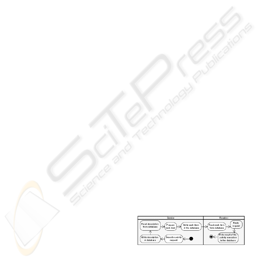
2.1.1 Unidirectional Performative Pattern
A sender uses unidirectional performative messages
to request the execution of an activity from a re-
ceiver. Figure 2 shows the pattern: an activity execu-
tion request results in a work item being assigned to
a receiver (i.e., a specific workflow participant re-
sponsible for activity execution). After that, the
process may continue execution without waiting for
a response. Note that the unidirectional performative
message does not require a response.
Figure 2: Unidirectional Performative pattern.
ICEIS 2007 - International Conference on Enterprise Information Systems
448
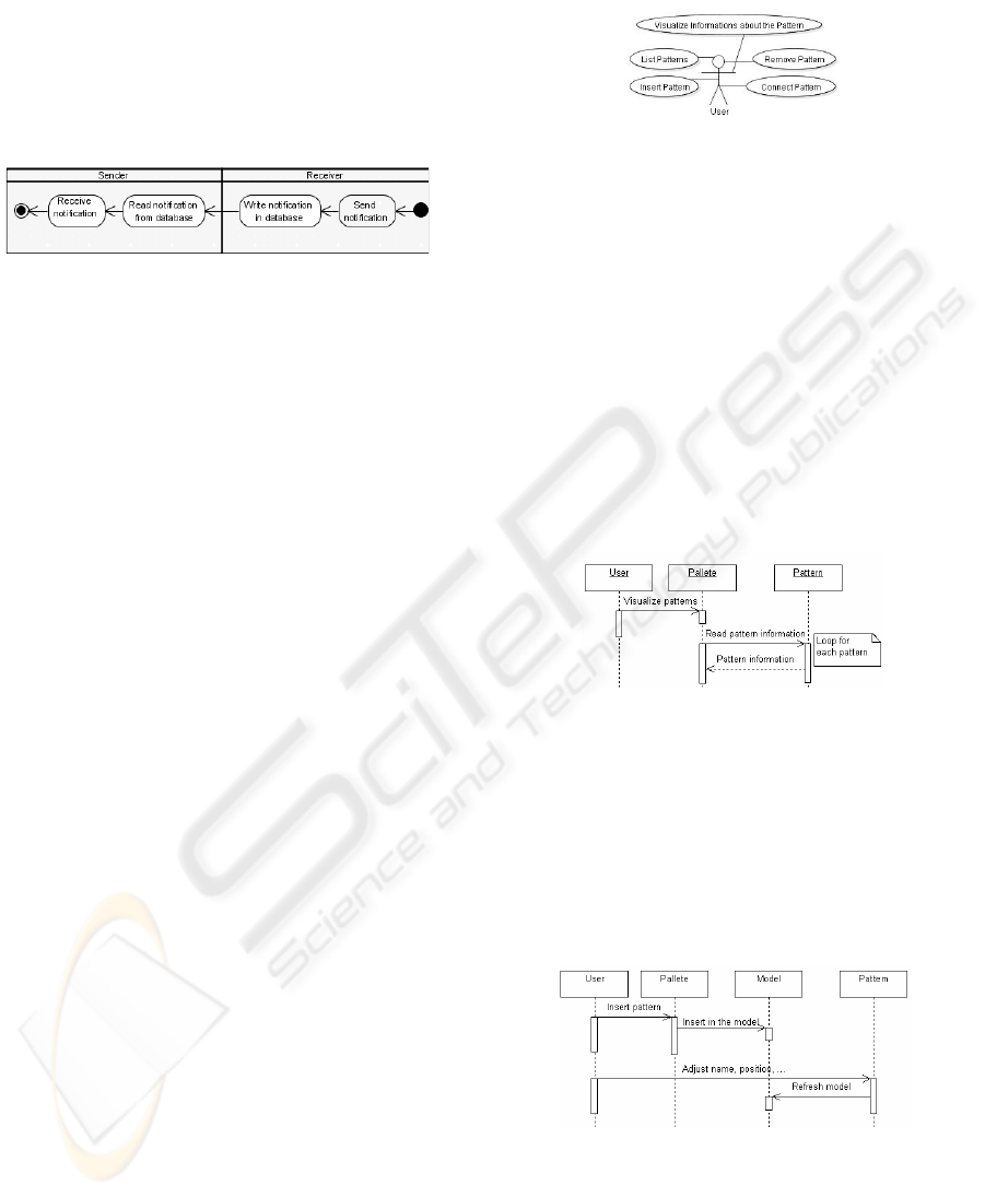
2.1.2 Notification Pattern
This pattern comprises a notification activity that
either informs about the completion of an activity
execution or posts news inherent to the respective
workflow application (e.g., a notification about the
result of an approval process) (cf. Figure 3). In the
present approach it is assumed that a notification
activity status may eventually be sent if requested.
Figure 3: Notification pattern.
3 REQUIREMENTS FOR
PATTERN REUSE IN TOOLS
This section introduces the requirements for extend-
ing a generic business process modeling tool with
the workflow patterns introduced in Section 2.
Note that the requirements focus on the design
phase of the workflow model assuming that execu-
tion issues are handled by a workflow management
systems (WfMS). The requirements are specified as
use case diagrams and descriptions, and as sequence
diagrams illustrating the interactions between ob-
jects of some business process modeling tool.
The use cases diagram represents the functional-
ity that is expected by users while working with a
process modeling tool based on the reuse of work-
flow patterns. Each use case illustrates a possible
interaction between the user and the tool respec-
tively. Such interactions give the behavioral notion
of the application. The corresponding use cases de-
scriptions are the base for the subsequent specifica-
tion of the sequence diagrams. Each use case de-
scribes possible responses expected by a process
design tool to user actions. Finally, the sequence
diagram map the classes involved in a workflow
pattern reuse, as well as their interactions and corre-
sponding methods.
Beyond a pattern repository we need a mecha-
nism to exhibit patterns for selection to the user. At
the present, our approach supports manual selection.
However, we aim to improve this selection towards
a semi-automatical mode by the help of rules that
specify patterns interactions and combinations.
Regarding the subsequent UML diagrams the
high level of abstraction serves the applicability for
different kinds of modeling tools. Specific interface
aspects are neglected. The sequence diagrams also
present the objects and methods in a way that does
not refer to some specific tool (e.g., we do not spec-
ify parameters), giving more flexibility for the im-
plementation phase. These aspects are application
dependant and must be defined in implementation
time.
Figure 4: Use cases diagram.
Figure 4 shows the actor (user) as well as his
possible interactions with the system. It also shows
that the tool must provide the patterns stored in an
application dependant data structure, in order to be
able to respond to the specified use cases. Accord-
ingly, the UML patterns (cf. Section 3) have to be
mapped to a corresponding representation in the
notation of the tool being extended. Thus, they can
be stored as a composition of basic structures of
modeling language that is supported by the tool. For
each use case a sequence diagram was developed
(e.g., list pattern, view pattern, insert patter, connect
pattern and remove pattern). Figures 5 and 6, respec-
tively, show sequence diagrams for the two patterns
that we use to illustrate the approach.
Figure 5: List patterns sequence diagram.
Figure 5 presents the sequence diagram for the
use case List Patterns. The method Visualize Pat-
terns is a request made by the User to the Pallete in
order to visualize the workflow patterns stored in the
tool. After receiving this message, the Pallete lists
all stored patterns. For each one, it reads the pattern
information and displays a description of the Pattern
to the user.
Figure 6: Insert pattern sequence diagram.
Figure 6 illustrates the sequence diagram for the
use case Insert Pattern. It represents the use of the
workflow patterns in the modeling of a business
process. The User selects in the Pallete the structure
which he wants to add to the Model. After the Pat-
tern is included in the model, it must be changed
EXTENDING BUSINESS PROCESS MODELING TOOLS WITH WORKFLOW PATTERN REUSE
449
according to User commands (e.g., pattern name and
position adjustment). Each modification in the Pat-
tern is informed to the Model.
From these sample diagrams as well as the oth-
ers developed we can obtain the classes and respec-
tive methods involved in the implementation of this
project. The derived classes are pallete, pattern,
model and element for connection.
The Pallete represents a menu to the user for
choosing the pattern he wants to add to the model.
This might be a graphic, a button, or a drop down
list. The class Model represents the business process
that the user designs. It contains all modeling struc-
tures and their connections and displays it on the
screen. The class Pattern represents the pattern
stored in the format that the tool assumes.. The Ele-
ment for connection identified in the sequence dia-
gram of the use case Connect Pattern (used to de-
scribe how workflow patterns are connect to each
other as well as with other existent structures) repre-
sents an modeling element of the tool.
As these requirements refer to the extension of
an existing workflow design tool, probably some of
the identified classes will already exist, requiring
only a mapping between the classes of the project
and the classes of the implemented in the design
tool. In the subsequent sections, we focus on EPCs
as an example of a business process modeling lan-
guage and EPC Tools as a modeling tool.
4 EPCS AND EPC TOOLS
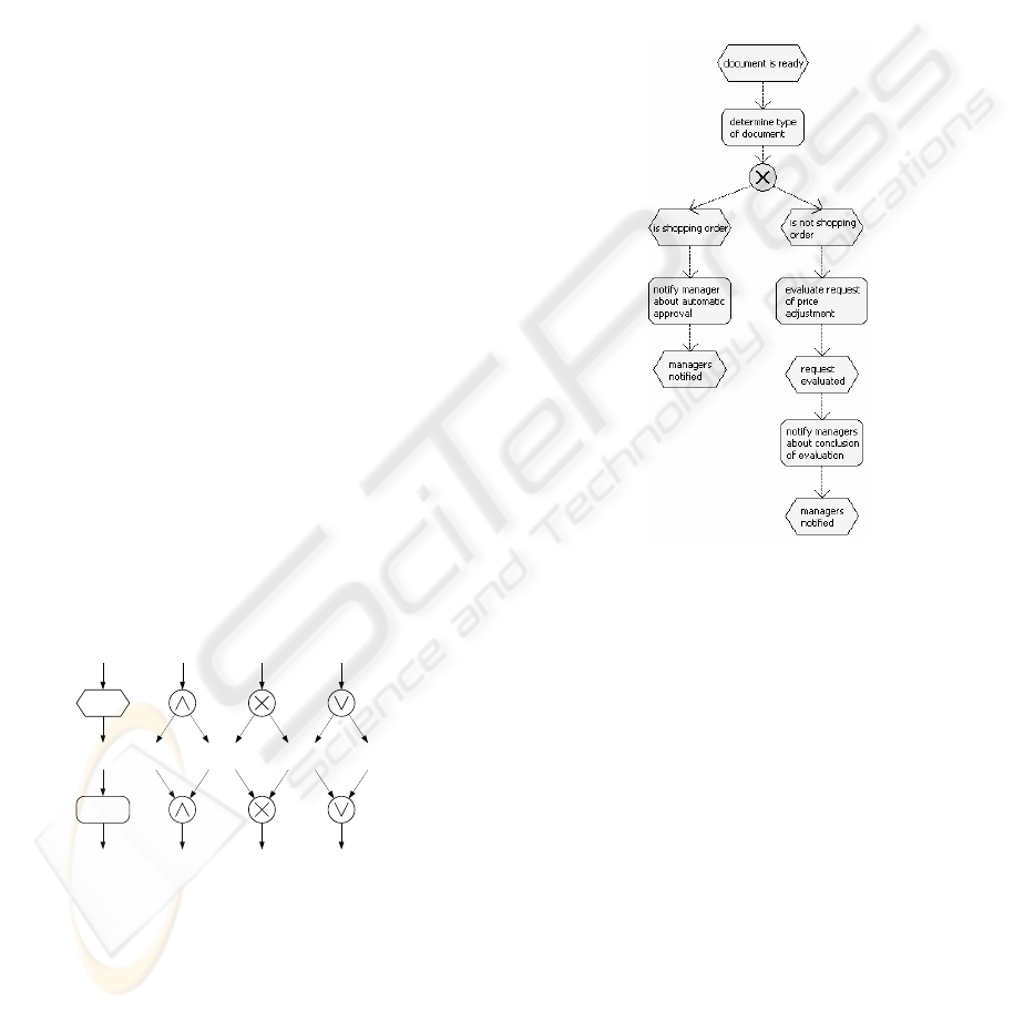
The Event-driven Process Chain (EPC) is a business
process modeling language that captures the tempo-
ral and logical dependencies between activities of a
business process (Keller, Nüttgens, and Scheer,
1992) and later formalized by different authors (see
Mendling and Aalst, 2006). EPCs offer three ele-
ment types: functions, events, and connectors. Func-
tion type elements to represent activities of a busi-
ness process while event type elements describe the
pre- and post-conditions of the functions. Connec-
tors specify complex routing constraints. They must
be either a split or a join and define a connector type
of either AND, XOR, or OR.
The different connectors behave as follows. The
AND-split activates all subsequent branches in con-
currency. The XOR-split represents a choice be-
tween one of alternative branches. The OR-split
triggers one, two, or up to all subsequent branches.
The AND-join waits for all incoming branches to
complete, then it forwards control to the subsequent
EPC element. The XOR-join merges alternative
branches. The OR-join synchronizes all active in-
coming branches. This feature is called non-locality
since the state of all transitive predecessor nodes has
to be considered.
Figure 8: Example of an EPC.
Figure 8 gives the example of an EPC process
model for the workflow process of Figure 1. After
the document is read, its type is determined. If it is a
shopping order, the manager is notified of automatic
approval and a request is sent. If not, the price is
adjusted manually and the managers are notified.
The importance of EPCs for business process
modeling stems from two facts. First, EPCs are
heavily used in practice due to extensive support,
e.g. by ARIS toolset of IDS Scheer AG, and because
it was used as a language for a redocumentation of
SAP’s enterprise software; see Keller and Teufel
(1998). Second, EPCs include OR-joins that pose
theoretical challenges due to its non-locality, i.e. it
synchronizes only those branches that are active.
This feature has in particular stimulated research by
Kindler (2006) which resulted in an implementation
called EPC tools (Cuntz and Kindler 2005).
EPC tools is among the few tools for business
process modeling that are both open source and pro-
vide sophisticated simulation and verification fea-
tures. The simulation facility offers the modeler an
Event AND-Split XOR-Split OR-Split
Function AND-Join XOR-Join OR-Join
Figure 7: EPC Notation and informal semantics.
ICEIS 2007 - International Conference on Enterprise Information Systems
450

interface to propagate cases through the process in
order to check whether the behave is described ap-
propriately. Moreover, the verification facility ana-
lyzes whether the process is sound (i.e. live and
bound) and contact free. EPC Tools is available as a
plug-in for the eclipse platform that can easily
adapted and extended. Furthermore, it supports the
open exchange format EPC Markup Language
(EPML), see Mendling and Nüttgens (2006).
5 EXTENDING EPC TOOLS
WITH PATTERN REUSE
In this section we describe the extension of EPC
Tools with some of the workflow patterns intro-
duced in Section 2. The extension was based on the
requirements introduced above. In order to support
the patterns we extended the code of the tool.
The new features added follow the general inter-
face design of the tool (e.g., font type, buttons style
and labels size). This provides an integration that is
almost imperceptible for the user which simplifies
the use of the workflow patterns through the tool.
The implementation started with the interface
definition. First we defined the position of the pat-
terns in the designer. After that, for each workflow
patterns we created a button. To identify that these
buttons are related with patterns, it was also added a
label Patterns in the tool interface.
This implementation covers the use case Insert
Pattern. As discussed in Section 2 the number of
workflow patterns needed for the definition of a
process is small (no more than 7 or 9). Thus, the use
case List Patterns is implemented by the patterns
buttons that present to the user the available patterns
stored in the tool. As the patterns buttons are visible
as soon as the tool is started, the use case List Pat-
terns is executed only once when the tool is up-
loaded. The use case Visualize information about
patterns is implemented through the patterns buttons
too. When the user rolls the mouse over a specific
pattern button a tooltip is presented.
To implement the other use cases (Insert Pat-
tern, Connect Pattern and Remove Pattern) the
classes identified in the sequence diagram were
mapped to corresponding entities that are already
available in EPC Tools. First, the class pallete had to
be added. Second, we mapped the class workflow
pattern to macros. Each implemented pattern was
translated from UML notation to EPCs (see Figure
9). When the user clicks the pattern button the corre-
sponding structure is inserted in the model. This
way, it was possible to reuse most of the code for the
basic EPC elements. Specific actions that manipulate
a pattern when it is inserted in a model are sent to
the EPC basic structures (e.g., functions, events,
connectors) that compose it.
There are two ways to store a pattern. First, they
are hardcoded in the application which is kind of
rigid. The second approach stores the macros repre-
senting the patterns as EPML external files. This
way, the implementation is much more flexible since
the external file can be changed without touching the
source code. Another advantage of the external
EPML files is that the patterns mapping can be im-
plemented with EPC Tools, as it is based on EPML.
With this alternative, we can use EPC Tools to
model the representation of the pattern in EPC and
stores it in an EPML file.
Third, the model class was mapped to the respec-
tive EPC Tools class. Fourth, the element for con-
nection class is captured by basic EPC structures.
Figure 9: EPC Performative unidirectional pattern.
This mapping captures the semantics of the pat-
tern represented in UML activity diagram (cf. Figure
2). The Start event comprises the activities which
must be executed by the WfMS that executes this
process and which are related to the parameter defi-
nition and activity request dispatch. Following the
start event we have an OR-Split connector. On the
left-hand side of this structure we represent the exe-
cution of the activity which was requested. This ac-
tivity must include its correct label when the macro
is inserted into the model to better represent the
business process being specified. On the right-hand
side of the OR-Split we have the workflow sequence,
indicating that the process does not stop to wait for
the completion of the activity which was requested.
This pattern was introduced into EPC Tools in an
EPML external file, and inherits all the benefits dis-
cussed before of flexibility and easiness of imple-
mentation.
Figure 10 brings the mapping of the notification
pattern. It indicates that the notification activity is
executed after the start event is fired.
Figure 10: Notification pattern mapping.
Despite the simplicity of this mapping, the busi-
ness process modeling which includes this structure
can be done with less effort by the user as it only
needs one click to add this structure in the model.
Otherwise, it would need seven mouse clicks and
editing of the labels to construct a structure like this
EXTENDING BUSINESS PROCESS MODELING TOOLS WITH WORKFLOW PATTERN REUSE
451

from the scratch (only with basic EPC structures).
This pattern is hardcoded into EPC Tools source
and, for this reason, cannot be changed by simply
modifying an external file.
In a case study related to the implementation of
these two patterns, we found a reduction of about
one third in the amount of clicks needed to insert the
structures in the model. We considered the reduction
of design effort (e.g., time as well as errors reduc-
tion) as an important aspect which points out to new
questions to be investigated as part of a future work.
6 CONCLUSIONS
While workflow patterns were defined for several
aspects related to process execution, the aspect of
recurrent business functions is only partially ad-
dressed by existing work. In prior work, we identi-
fied a set of nine workflow patterns that appear nec-
essary and sufficient to model an extensive set of
workflows from practice. In this paper we investi-
gated in how far process modeling tools can be tai-
lored to provide a direct support for pattern reuse.
Our contribution is a set of requirements the process
modeling tool has to address. In order to demon-
strate the feasibility we extended the open source
process modeling tool EPC Tools with such reuse
support. The main advantages of this approach can
be summarized as follows: (a) the completeness and
necessity of the workflow patterns for the workflow
process design had already be evidenced in prior
work; (b) the proposed requirements are tool-
independent and can be adapted for any business
process modeling tool; (c) the requirements were
extensively tested in the case of an existent open-
source design tool; (d) we provided first evidence
that the workflow patterns integrated in a design tool
may reduce the design effort.
The main limitation faced with EPC Tools was
the lack of some concepts (e.g., block activity, role)
that are covered in the original UML version of the
workflow patterns. In the future we aim to investi-
gate whether the modeling phase of a workflow pro-
ject will result in a performance gain through the use
of workflow patterns such as the ones proposed in
this paper. To do so, it is yet necessary to perform
experiments that compare design time with and
without a pattern management tool integrated into a
workflow design editor (e.g., EPC). In conjunction
with the experiment, we consider a questionnaire to
find out whether less design effort could result in a
higher user acceptance of process modeling in gen-
eral.
REFERENCES
Aalst, W.M.P. van der; Hee, K. van, 2002. Workflow
Management: models, methods, and systems. London:
The MIT Press.
Bradshaw, D.; Kennedy, M.; West, C, 2005. Oracle BPEL
Process Manager. Developer’s Guide.
Cuntz, N.; Kindler, E., 2005. On the semantics of epcs:
Efficient calculation and simulation. In: BPM 2005,
Proceedings, volume 3649 of Lecture Notes in Com-
puter Science, pp.398–403.
Flores, F.; et al. 1998. Computer Systems and the Design
of Organizational Interaction.
Keller, G.; Nüttgens, M.; Scheer; A.-W., 1992.
Semantische Prozessmodellierung auf der Grundlage
“Ereignisgesteuerter Prozessketten (EPK)”. Heft 89,
Institut für Wirtschaftsinformatik, Saarbrücken, Ger-
many (in German).
Keller, G.; Teufel, T., 1998. SAP(R) R/3 Process Oriented
Implementation: Iterative Process Prototyping.
Kindler, E., 2006. On the semantics of EPCs: Resolving
the vicious circle. Data Knowl. Eng., 56(1):23–40.
Malone, T. W.; Crownston, K.; Herman, G. A, 2004. Or-
ganizing Business Knowledge.
Medina-Mora, R., 1992. The action workflow approach to
workflow management technology.
Mendling, J; Aalst, W. M. P. van der, 2006. Towards EPC
Semantics based on State and Context. In: Proceed-
ings of the 5th EPC Workshop EPK 2006, CEUR.
pp.25-48.
Mendling, J.; Nüttgens, M., 2006. EPC Markup Language
(EPML) - An XML-Based Interchange Format for
Event-Driven Process Chains (EPC). In: Information
Systems and e-Business Management, 4(3):245 – 263.
Muehlen, M. zur, 2002. Workflow-based process control-
ling: foundations, design, and application of work-
flow-driven process information systems. Berlin: Lo-
gos Verlag. 299 p.
Russell, N.; Hofstede, A. H. M Ter; Edmond, D., 2005.
Workflow Data Patterns. In: Proceedings of the 24th
ER, pp. 353-368.
Russell, N., 2004. Workflow Resource Patterns. Brisbane:
Queensland University of Technology.
Russell, N.; Aalst, W.M.P. Van Der; Hofstede, A. Ter. ,
2006. Workflow Exception Patterns. In: Proceedings
of 18th CAiSE, 18, p.288-302.
Thom, L. H.; Iochpe, C.; Amaral, V. L. do; Viero, D. M.
de, 2006. Toward block activity patterns for reuse in
workflow design. In: Workflow Handbook of WfMC,
pp. 249-260.
Thomas, O.; Scheer, A.-W., 2006. Tool Support for the
Collaborative Design of Reference Models - A Busi-
ness Engineering Perspective. In: 39th HICSS-39
2006), CD-ROM / Abstracts Proceedings.
Workflow Management Coalition (WfMC), 2005. Process
Definition Interface: XML Process Definition Lan-
guage. Doc. Number: WFMC-TC-1025. 2005.
ICEIS 2007 - International Conference on Enterprise Information Systems
452
