
CONCEPTS OF MODEL DRIVEN SOFTWARE DEVELOPMENT IN
PRACTICE
Generic Model Representation and DSL Interpretation
Christian Erfurth, Wilhelm Rossak, Christian Schachtzabel
Department of Computer Science, Friedrich Schiller University Jena, Ernst Abbe Platz 2, Jena, Germany
Detlef Hornbostel, Steffen Skatulla
IBYKUS AG for Information Technology, Erfurt, Germany
Keywords:
Model Driven Software Development (MDSD), Domain Specific Language (DSL), DSL-Interpreter.
Abstract:
This paper discusses possibilities to realize constructs of a domain specific model (DSL) on the concrete
development and runtime platform Ibykus AP. Here software engineering takes advantage of a combination
of generative techniques and stable so-called DSL interpreters. These techniques to implement model driven
software development (MDSD) concepts can improve the flexibility, the quality and the performance of the
development of large application systems. Presenting the DSL interpreter approach underlying techniques
of generic repository structures to hold the software model as well as runtime configuration information are
discussed. The importance of an associated clear and well structured interface and tuning alternatives for the
repository are pointed out. Finally the paper concludes with an outlook to future research work.
1 INTRODUCTION
In the area of generative software development differ-
ent approaches have been arisen (Czarnecki, 2004).
Starting from the state of the art we will look at prac-
tical implementation. Some challenges occurring in
practice are picked up and discussed, like e. g. model
data storage.
1.1 State of the Art of Generative
Development
In software development generative techniques are an
efficient way to produce software product artifacts.
Depending on the development methodology the us-
age of generators is very different. On the one hand
there are generators which work with abstract models
e. g. domain specific models. With these generators
the level of abstraction can be reduced stepwise by
transforming abstract input into less abstract output.
On the other hand generators are used to complete
implementation details such as standard class meth-
ods or documentation. Independent from the con-
crete purpose a software company aims to speed-up
software development, to strengthen quality, and to
achieve higher software reuse by applying generative
techniques.
In recent years different approaches for an im-
provement of software development processes and of
software quality have been defined. For a success-
ful application of these approaches an automation of
steps is essential at least in parts. In doing so, imple-
mentation mistakes of well-understood issues can be
avoided. Furthermore it enables system developer to
model complex systems in an adequate way focusing
rather on application level domain objects and their
processing than on technical implementation aspects.
The implementation of thereby used model elements
is carried out by generators on basis of mapping rules.
The role of code generation is a fundamental one:
Model transformation, software reuse, development
and usage of domain specific languages, etc. are ap-
plication domains. For the state of the art common
approaches will be discussed in brief.
1.1.1 Domain Specific Languages
Domain Specific Languages (DSLs) (Fowler, 2005;
Mernik et al., 2005) are expressive languages which
are used in special domains to outline a problem
space. Requirements are described formally using
278
Erfurth C., Rossak W., Schachtzabel C., Hornbostel D. and Skatulla S. (2007).
CONCEPTS OF MODEL DRIVEN SOFTWARE DEVELOPMENT IN PRACTICE - Gener ic Model Representation and DSL Interpretation.
In Proceedings of the Ninth International Conference on Enterprise Information Systems - ISAS, pages 278-286
DOI: 10.5220/0002384802780286
Copyright
c
SciTePress

conventional words of the client and with client’s se-
mantics. With DSLs domain experts are able to de-
scribe the problem space in their language. So the
necessary formalization can be done in cooperation
with IT-consultants using a suitable DSL. The model
of the software product contains apparently the con-
cepts of the client.
1.1.2 Model Driven Software Development
The fundamental idea of Model Driven Software De-
velopment (MDSD) (Mellor et al., 2003; Stahl and
V
¨
olter, 2006) is to separate the model of an software
product from technical details. Two aspects play a key
role: The first technological one is to support inter-
operability and portability in software systems to be
developed. Usually application software models are
more durable than the technologies used to implement
the system. While knowledge is formalized within the
model technical implementations can be exchanged.
DSLs are used in the formalization process. Once the
model is presenting the desired system it can be trans-
formed stepwise to an implementation system using
generative techniques. The second conceptual aspect
is to strengthen the use of abstraction in the process
of software engineering. The domain expert and the
application engineer are able to focus on the domain
logic while the developer of the modeling and genera-
tion environment can focus on details of the technical
implementation.
The concepts of MDSD are applied successfully
in the area of software architectures e. g. in the EJB
sector. A software architect describes the system us-
ing platform independent terms like component, in-
terface, etc. The meaning of these terms has to be
specified with a mapping to concepts of the target
platform. The specification of mapping can be in-
tegrated into code generators or interpreters. So the
meaning of a term like component is known to a gen-
erator and can be transformed in concepts of the plat-
form. The generator produces the skeleton of the ap-
plication. Only those parts of the application have to
be hand coded which are hard to formalize platform
independently. A change of the platform results in a
change of the mapping rules. The application logic
within the model is not affected.
A special form of MDSD is the Model Driven
Architecture (MDA) which is a standard defined by
OMG (OMG, 2006). It focuses on interoperability
and portability. MDA requires an MOF-conform de-
scription language, e. g. UML, in contrast to MDSD
which does not postulate a certain language. The
standard proposes different models (CIM - Compu-
tational Independent Model, PIM - Platform Indepen-
dent Model, PSM - Platform Specific Model) which
can be annotated for transformation steps.
1.1.3 Software Factories
The idea of Software Factories (Greenfield et al.,
2004) or Generative Programming (Czarnecki and
Eisenecker, 2000) can be compared with automated
industrial production processes such as the assembly
process of a car: A software product is no longer
programmed but is assembled using standard compo-
nents. Therefore reuse is essential. The tool to as-
semble the software is programmed - the assembly
line. Software developer’s work is reduced to con-
figuration mainly. Programming mistakes are nearly
impossible. Configuration and reuse boost generative
techniques to create standard components.
1.2 State of the Art in Practice
Different approaches to improve the software devel-
opment process are in the focus of research and are
already used in practice in some areas. But the en-
tire potential is not used yet. For different abstraction
levels different models are used. This causes consis-
tency problems: client and software developer work
on different models. One model with different views
can avoid such problems.
Generators play an important role in MDSD.
Through generative techniques large parts of software
artifacts are produced automatically. Changes are
mapped to application code by transforming models
and applying generators. But up to now interpreters
are not in the focus of MDSD although the benefit can
be high and especially the flexibility can be pushed.
Applications of a larger size may demand a cer-
tain level of stability and flexibility. Stable data struc-
tures for (changing) application data and a fixed in-
frastructure which allows flexible changes on appli-
cation level could be essential for successful usage at
customer’s site. A combination of generative tech-
niques and stable interpreters are used by Ibykus AP
as described in the next section. Concepts of MDSD
can be found in the software of this company. Fur-
thermore the following section of the paper describes
concepts of MDSD which are already used in prac-
tice.
CONCEPTS OF MODEL DRIVEN SOFTWARE DEVELOPMENT IN PRACTICE - Generic Model Representation and
DSL Interpretation
279

2 APPLYING MDSD IN
PRACTICE
2.1 Ibykus AP Platform
One example for such a practical approach is the gen-
erative development and interpretative runtime envi-
ronment Ibykus AP (Ibykus, 2007). It is focused
to build large application systems in the domain of
business, administration and governmental processes.
Ibykus AP has been used to successfully develop a
number of complex software systems during the last
7 years e. g.
• systems for the management of agricultural
promotion fonds of the European Union, the
controlling of financial resources and other e-
governmental administration processes in several
German federal states,
• applications to support business processes like
claims and contract handling, project and inno-
vation management as well as other industrial
projects.
The generative development process of Ibykus AP
is based on a repository to hold a comprehensive
model of the software application to be built. The
modeling is based on concepts like domain specific
application classes like Process, Process Participant,
Data Object and others. These domain classes can
be interrelated and be equipped with data attributes,
processing algorithms, workflows and more domain
specific modeling features. Practical experiences in
modeling application logic prove the inadequateness
of UML based DSLs, at least in the domain of admin-
istrative and business process management. Profes-
sionals in this area regularly do not accept and com-
prehend UML based DSLs as means of expression for
analysis and design of application logic: misunder-
standings and mistakes did occur. Therefore at Ibykus
an informal notation with a fixed set of simple graph-
ical elements to represent the mentioned conceptual
items is used. It has to be emphasized, that the mod-
eling can be completely focused on to the application
domain level. No technical aspects like data storage,
transaction and error handling, user interface events,
recording of histories need to be modeled explicitly
then. These are all addressed by the software genera-
tion process and the interpretative runtime component
of Ibykus AP as shown in figure 1.
Based on the software model on the one hand
the application specific processing logic and the sur-
rounding technical support code are generated. On the
other hand runtime configuration structures are popu-
lated to implement the structural aspects of the target
application. This configuration is interpreted by the
Ibykus AP runtime system to establish the infrastruc-
ture needed to run the built application. A stable stor-
age structure is dynamically configured to keep the
needed application data and likewise the GUI is con-
figured.
2.2 Combining Code Generation and
DSL Interpretation
DSLs are an expressive way to formally de-
scribe stakeholder’s requirements and the resulting
application-level software design in domain specific
terms. The process of transforming these DSL models
into platform specific models is often done with help
of generative techniques. A stepwise transformation
(model-model-transformation) can also be applied as
proposed by MDA. Code generation is only one pos-
sibility to extract (parts of) the final application.
A different option to DSL-based code generators
would be DSL interpreters. Such interpreters work on
the runtime level of a system. DSL terms will be read
by an interpreter and translated into operations on the
targeted platform. At runtime a DSL interpreter de-
cides how to map a specific DSL term onto the plat-
form. For instance the DSL term booking has a field
amount. If a user creates a new booking the field (text
control) amount is displayed as a part of the form on
the screen by the DSL interpreter. After submitting
this form the interpreter inserts a corresponding entry
into the database.
But, do we need to decide between an interpre-
tative or generative approach? Generators and in-
terpreters do not rule out each other. Far from it!
The construction of software could benefit of a mix-
ture of these approaches much more. En route from
High-Level DSL terms to computer platforms a first
generative step results in intermediate language con-
structs. These constructs are interpreted at run time by
a generic interpreter. Thereby, the intermediate lan-
guage could be a script-based programming language
or a Low-Level DSL or even entries in some control
structures.
In both approaches modeling is done application-
domain- and customer-oriented. Fundamental con-
cepts of MDSD/MDA have to be kept in mind. In
the end DSL interpreters and DSL generators are a
different technical implementation of the same con-
cept. A DSL interpreter works on the logical level
of a DSL. The main functionality is part of the run-
time level while in case of generative programming
the knowledge of the architecture is within genera-
tors.
One example for a concrete usage of the concept
ICEIS 2007 - International Conference on Enterprise Information Systems
280
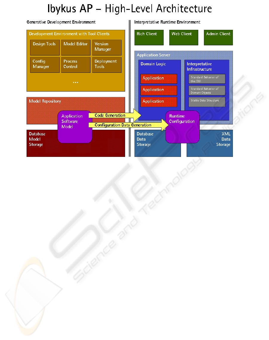
Figure 1: Architecture and main components of Ibykus AP.
of the combination of generative and interpretative
techniques is Ibykus AP. As figure 1 shows, the Appli-
cation Software Model as a High-Level DSL is built
up in the Generative Development Environment. Be-
sides the generation of code parts the model elements
are automatically transformed into runtime control in-
formation to build up the executable software system.
This control information in turn is interpreted by the
Runtime Environment to display, process and store
application level objects like booking.
The approach of Ibykus AP is to improve the flex-
ibility of application software and its engineering by
using MDSD. This is illustrated in figures 2 and 3.
Figure 2 presents the model of a reference between
two application domain classes: as a booking has got
an associated payee a reference form BUC to ZPA is
defined. And figure 3 shows the resulting GUI inter-
pretation of the runtime configuration generated from
the model: in the booking form the reference is rep-
resented by two data fields with some identifying and
describing information for the referenced payee and
by one button to navigate to the payee form and to al-
ter the associated payee. In fact the display of these
GUI elements is an interpretation of runtime config-
uration entries, that can be altered at runtime. In ad-
dition to the modeling and generation of the runtime
configuration it is possible to create, alter and remove
GUI elements in an already running application. Of
course this can be guarded by an appropriate user, role
and permission management.
2.2.1 Generic Concept
A model representation is needed in both cases: For
interpreters as well as for generators. Changes in the
model have no effect on the runtime level i. e. an
interpreter remains unchanged and has to be generic
therefore. Furthermore a generic repository is neces-
sary which is able to store various models. The meta
model of such a repository is in a schema-instance-
relation with the concrete model. But how can we
determine this meta model? One way is to store the
meta model and the model within the same reposi-
tory. With this generalization, different DSLs can be
stored within the generic repository. The meta model
is common for the repository and the models of the in-
terpreter and generator. An interpreter is also able to
acquire information on used modeling language. So
a DSL becomes flexible and can be extended without
changing the interpreter. The generic structure of the
data model used for the (run-time) repository can be
fixed. This is an advantage for interpreters which nor-
mally may not change over lifetime.
How can we achieve that model, configuration and
CONCEPTS OF MODEL DRIVEN SOFTWARE DEVELOPMENT IN PRACTICE - Generic Model Representation and
DSL Interpretation
281
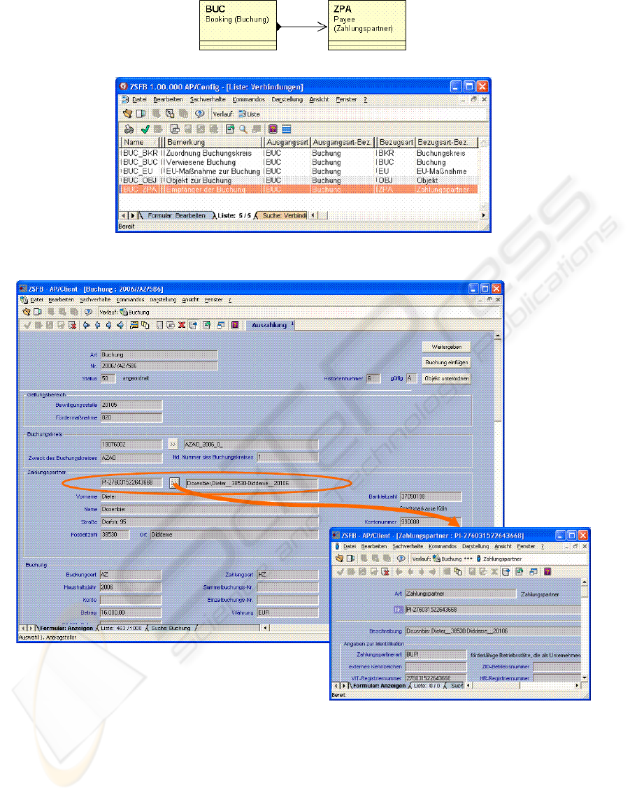
Figure 2: New model entry: Reference from Booking to Payee.
Figure 3: Resulting GUI elements for data and navigation.
application data can be stored generically in the same
way without changing repository schemes? Though
UML representations like XMI, MOF-based main
memory object representations and model transfor-
mation as well as code generation techniques are sup-
ported by a great variety of utility software and frame-
works Ibykus AP uses a model representation in a
relational database. The reasons are the following:
First, 7-10 years ago when Ibykus AP emerged, none
of these concepts and tools existed. Secondly, the
model querying and retrieval capabilities of a rela-
tional database are superior and faster by far, what is
essential especially for the online interpretation.
How generic shall such a database representation
ICEIS 2007 - International Conference on Enterprise Information Systems
282
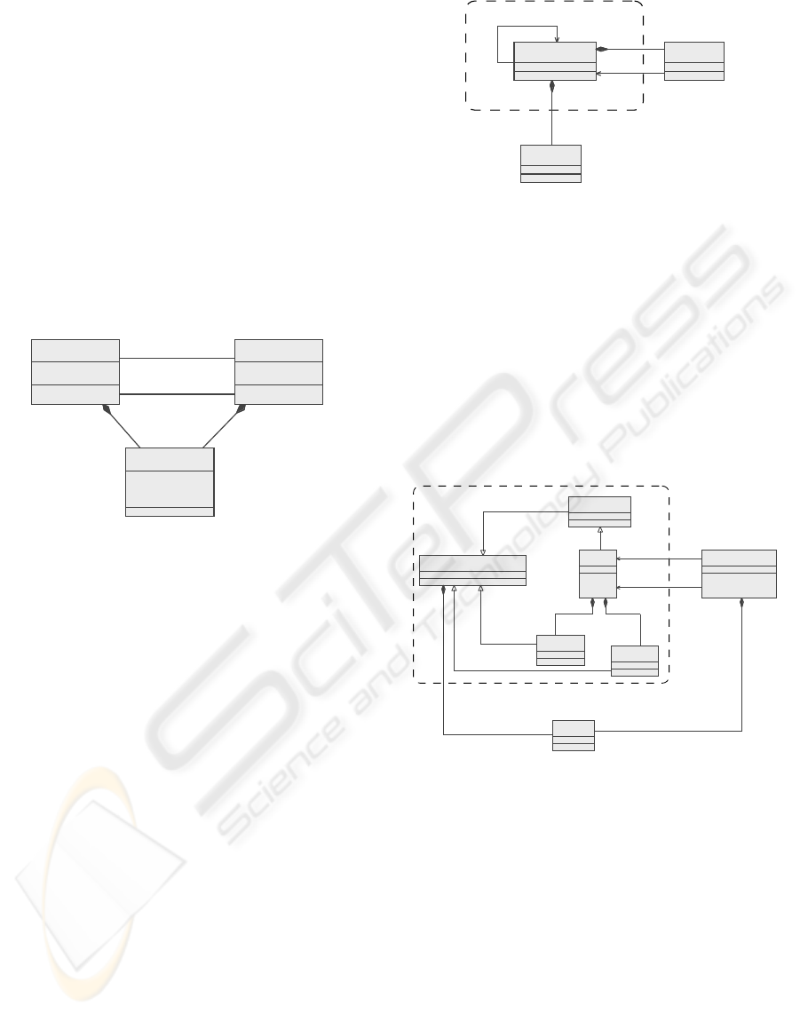
be? Looking at most graphical modeling languages
a Node-Arc-Property-Model (NAP model, see fig-
ure 4) is sufficient to map any language constructs.
All DSL modeling elements are represented as in-
stances of Node and their interrelations and depen-
dencies as instances of Arc. Both, Nodes as well as
Arcs are attributable by instances of Property. This
model representation – mathematically denoted by
annotated graphs – is suitable for any DSL and mod-
eling constructs. In consequence the NAP model is
independent from a specific application which is es-
sential for a generic interpreter. A similar approach
is the GOPRR-Model (Graph, Object, Property, Rela-
tionship, and Role (Kelly, 1997)) used in MetaEdit+
from MetaCase (MetaCase, 2007)
Arc
+name : String
Node
+name : String
Property
+name : String
+value : String
+incoming
*+to
1
+outgoing
*
+from
1
*
0..1
*
0..1
Figure 4: NAP structure.
In Ibykus AP an application data storage model
was developed on the basis of such a generic model
as shown in figure 5. All domain objects are stored
as instances (data records) of domain class. It em-
braces an optional parent reference as well as a num-
ber of fixed parameters like the internal numerical id,
an additional domain level identification called ident,
a textual object description desc, the object’s state and
other parameters that are mandatory for all objects.
More freely definable application specific parameters
and relations to other domain objects are represented
as instances of parameter and reference. With respect
to this data model in practice it turned out that data
migration due to new software versions is not neces-
sary. This is a huge benefit in areas with regularly
changing application demands like the permanently
adapted agricultural promotion programs of the EU
and others.
Regarding the structures to hold the software
model repository and the runtime configuration it is
important to mention that both adhere to the same
generic representation concept even though they are
usually stored in two different system environments:
the first in the generative development environment
and the second in the interpretative runtime environ-
ment.
Domain Class
Parameter
Reference
Node
+to
1
*
*
+Parent Class
0..1
Figure 5: Application data storage model (simplified).
In the model repository of Ibykus AP (figure 6) all
domain classes are described as instances of type. A
type can have freely modelable data parameters (do-
main class attributes) and commands (domain meth-
ods). Types can be interrelated with a number of de-
finable relations. Additionally each domain type is
derived from a certain predefined base type which
provides a set of basic domain specific attributes, pro-
cessing logic and other properties. Details of all these
modeling elements are to be described by associated
attributes.
AttributeableElement
Relation
Base Type
Type
Command
Parameter
Attribute
Node
1..*
1
+from
1
*
+to
1
*
1..*
1..*
Figure 6: Storage structure of software model repository
(simplified).
The AP runtime structure (figure 7) is optimized
for fast interpretation as discussed later on. It stores
the information in terms of a hierarchy of configura-
tion components, configuration elements and config-
uration parts which are fleshed out by attributes and
interconnected by references.
Of course modeling is not done directly with NAP
or its derived model representation structure. In the
upper part of figure 2 a sample of the GUI used for
DSL modeling in Ibykus AP is shown. It allows cre-
ating all needed application level object classes and
the relations between them, to define the required pro-
cessing commands and procedures as well as to spec-
ify all other domain-level aspects of the resulting ap-
plication. To build the final application software the
CONCEPTS OF MODEL DRIVEN SOFTWARE DEVELOPMENT IN PRACTICE - Generic Model Representation and
DSL Interpretation
283
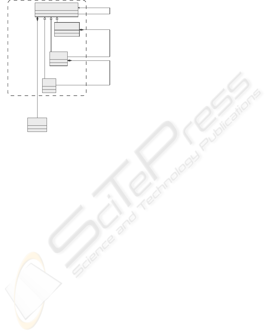
ReferencingElement
Component
Attribute
Element
Part
Node
*
*
*
+Reference
0..1
Figure 7: Storage structure of runtime configuration (sim-
plified).
DSL elements are associated with fragments in an
overall generation system. In this process each mod-
eled item is transformed into application code or con-
figuration entries in the generic runtime configuration
or both.
2.2.2 A Boost of Flexibility
With DSL interpreters modeling and configuration is
very flexible and can be done even at runtime. While
the technical base (architecture) is fixed, functional
changes can be made by developers or even by cus-
tomers themselves.
Using AP, it is possible to model the applica-
tion roughly and to install the platform at customer’s
site. Changes and refinements are made together with
stakeholders. Results of non-structural changes like
the addition of application class attributes for instance
can be made effective directly. Structural changes
like the definition of new application classes require
a repetition of the automatic generation process. For
example, in AP a new relation between two applica-
tion classes can be added within minutes (GUI, nav-
igation, application logic and database storage – see
figure 2) at customer’s site. The changed parts of the
customized model can be synchronized into the repos-
itory at developer’s site later if reasonable. Using this
kind of prototyping the period of time to understand
complex requirements is reduced significantly. These
short feedback cycles enable agile software develop-
ment.
2.2.3 Generative Vs. Interpretative Approach
Independent from the question which approach is ap-
plicable, the explicit preparation of domain knowl-
edge is very important. This knowledge can be inte-
grated in generators or interpreters. Especially excep-
tion handling and the missing compiler step raise the
effort to implement an interpreter. But the additional
work amortizes very fast if the gained flexibility is
necessary and used.
• Pro generator
– fast program execution
– less effort to program than interpreters
– easier to debug
• Pro interpreter
– high flexibility
– deployment of new application versions is eas-
ier (e. g. no client update)
– old and new software version are executable at
the same time
– low probability for data migration
– migration to new versions affect only func-
tional and no technical level
2.3 Runtime Tuning
In practice often special runtime requirements need to
comply. Due to the generic nature of the NAP model
the real storage model has to be adapted. Thereby it
is important to keep concepts of this model in mind.
With the following performance optimization the log-
ical model and their interfaces remain unchanged.
Tuning is a technical activity to improve runtime
performance. Tuning on repository level does not re-
quires any changes of DSL interpreters. It has also no
effect on modeler. One possible tuning activity is a
breakdown of data base normalizations.
For instance in the application data store (figure 5)
the heavily used relation between child and parent
data records are represented directly as a reference.
And all other references are aggregated as contained
elements of the referring data record. By separat-
ing the relations into different storage alternatives the
storage structure is optimized below its logical inter-
face in order to speedup storage and retrieval opera-
tions.
Another tuning method is applied to the runtime
configuration data structure (figure 7): to increase the
retrieval speed for interpretation the configuration el-
ements (nodes in NAP) are classified along their nest-
ing hierarchy. Program components are master ele-
ments without a parent. They contain elements as ma-
jor configuration items which in turn contain parts as
ICEIS 2007 - International Conference on Enterprise Information Systems
284
minor items. All of them are characterized in detail
by attributes and can have references to other config-
uration items.
So in practice all three structures, the software
model repository, the runtime configuration and the
application data store, are optimized in their physical
storage table layout to support their respective pro-
cessing demands: modeling and generation on the one
side and runtime interpretation and data processing on
the other.
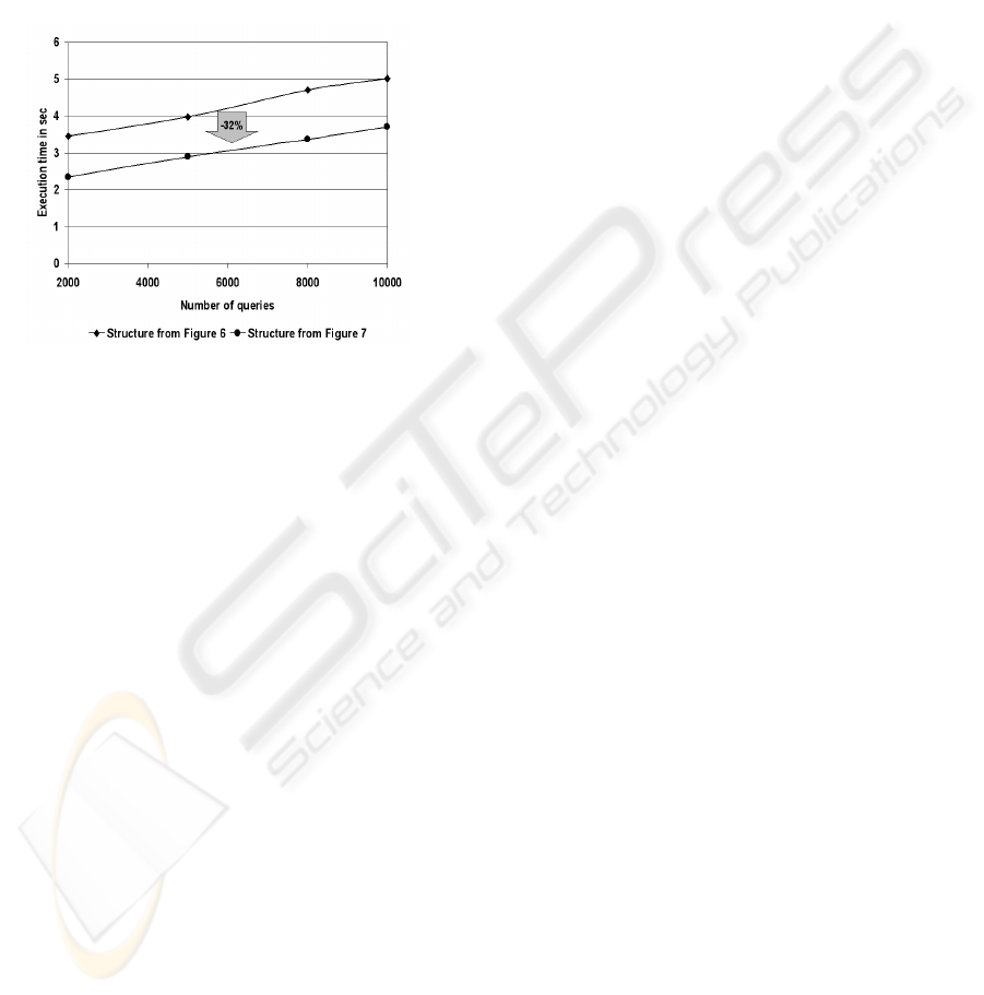
Figure 8: Retrieval performance utilizing different storage
structures.
Figure 8 points out the potential of storage struc-
ture optimization by comparing the storage structures
shown in figure 6 and 7. Slightly exceeding 80,000
model elements in hierarchies of approximately 5 lev-
els and a fan-out of about 4 on each level were stored
using both structures. A number of queries were pro-
cessed retrieving model elements and their parent el-
ements up to the root. The recorded query execution
times indicate a significant reduction by 32% using
the optimized structure.
Additionally these structures can be partitioned
into data sets that are restricted to their respective de-
mand. For instance the GUI interpreter does not need
any information about data storage configuration. So
a repository partition can be used that is restricted to
hold only the GUI configuration. This concept could
be extended in a way that a complete physical reposi-
tory is not existent at all. But nevertheless, this is only
a technical optimization issue, the repository interface
is not affected at all and logically the repository as a
whole is at hand for each component.
Due to historical reasons, tuning possibilities in
AP are not covered behind interfaces completely. De-
veloper and modeler have the possibility to use the
tuned structures instead of the interface, but practice
suggests that the barrier should be very high.
3 CONCLUSION AND FUTURE
CHALLENGES
This paper discusses selected concepts of MDSD
which are applied in practice. Experiences with the
Ibykus AP platform show benefits of using such con-
cepts.
Especially, using the model driven generative soft-
ware development techniques with Ibykus AP, we ex-
perienced a boost of overall project performance of
20%-50%. Though it is rather difficult to number
the increase in efficiency, the records of more than
20 major projects in the last 7 years show this sig-
nificant reduction of project duration or team size
or increase of accomplishable project size or com-
plexity. One example shows the typical performance
boost quite well: A legacy accounting solution of
the German federal state of Niedersachsen process-
ing about 1.2 millions booking records per year with
about 15 sub-records each and an overall transaction
volume of about 800 million Euros was replaced with
a new solution. The legacy application had been de-
veloped over the last 10 years with 5-10 team mem-
bers. In contrast the replacement project required 7
team members, 11 months and surpassed the func-
tionality.
Furtheron it was pointed out that a generic data
structure is a good technological base to develop a
model repository to hold different aspects e. g. the
software model and the runtime configuration. On top
of that low-level format a domain specific language
can be used to model an application. A high-level
DSL is independent from technical realizations.
A generic data structure is a good base to develop
one model repository to hold different views of the
model e. g. the software model and the runtime con-
figuration. On top of that low-level format a domain
specific language can be used to model an applica-
tion. A high-level DSL is independent from further
technical realizations.
In an application a generic structure is also useful.
For performance reasons the generic structure has to
be adapted to special needs. One aspect can be us-
age frequencies of special entities or relations. Due to
such a stable data structure software version updates
do not affect customer’s data. Compatibility of data is
ensured completely.
Mostly MDSD is associated with generative ap-
proaches to transform models or to produce software
artifacts. But a combination of generative and inter-
pretative techniques leads to much more flexibility.
Changes within an application will be done on func-
tional level. ”On-line” modifications are possible and
can be done very fast while the technical base (inter-
CONCEPTS OF MODEL DRIVEN SOFTWARE DEVELOPMENT IN PRACTICE - Generic Model Representation and
DSL Interpretation
285

preter) remains unchanged.
Of course there are mismatches between concepts
of MDSD and practice. Regarding PSMs defined
in the MDA approach no explicit platform specific
model is available. But this model is implicit present
– in form of platform specific interpreters. The map-
ping from PIM to PSMs is integrated there.
Through applying MDSD in practice agile soft-
ware development can be implemented within an en-
terprise. But there are issues which need to be ob-
served in future. For instance incremental changes in
a model should not force a complete generation pro-
cess of all elements. Such a process consumes a lot
of time in large applications. In practice incremen-
tal generation of software artifacts are important for
the creation and deployment of software updates. Es-
pecially in e-governmental areas, changing require-
ments have to be processed and delivered very fast. A
future task will be to find a method to describe depen-
dencies between model elements on platform level.
Another question is how to handle different ver-
sions of a model. Often an application is delivered to
different customers. Main parts of the model are iden-
tical but some parts are customized. It is desirable to
have no copies of common parts because it can cause
inconsistencies and additional management work.
REFERENCES
Czarnecki, K. (2004). Overview of generative software de-
velopment. In Ban
ˆ
atre, J.-P., Fradet, P., Giavitto, J.-L.,
and Michel, O., editors, UPP, volume 3566 of Lecture
Notes in Computer Science, pages 326–341. Springer.
Czarnecki, K. and Eisenecker, U. (2000). Generative
Programming – Methods, Tools, and Applications.
Addison-Wesley Professional, first edition.
Fowler, M. (2005). Language Workbenches: The
Killer-App for Domain Specific Languages?
http://www.martinfowler.com/articles/
languageWorkbench.html.
Greenfield, J., Short, K., Cook, S., and Kent, S. (2004).
Software Factories: Assembling Applications with
Patterns, Models, Frameworks, and Tools. John Wiley
and Sons Ltd, first edition.
Ibykus (2007). Ibykus AP Version 2.12. http://www.
ibykus.com/.
Kelly, S. (1997). Towards a Comprehensive MetaCASE
and CAME Environment: Conceptual, Architectural,
Functional and Usability Advances in MetaEdit+.
PhD thesis, Jyv
¨
askyl
¨
a University.
Mellor, S. J., Clark, A. N., and Futagami, T. (2003).
Guest editors’ introduction: Model-driven develop-
ment. IEEE Softw., 20(5):14–18.
Mernik, M., Heering, J., and Sloane, A. M. (2005). When
and how to develop domain-specific languages. ACM
Comput. Surv., 37(4):316–344.
MetaCase (2007). MetaCase Homepage. http://www.
metacase.com/.
OMG (2006). MDA – Model Driven Architecture. http:
//www.omg.org/mda/.
Stahl, T. and V
¨
olter, M. (2006). Model-Driven Software
Development. John Wiley and Sons Ltd, first edition.
ICEIS 2007 - International Conference on Enterprise Information Systems
286
