
INTERACTIONAL OBJECTS: HCI CONCERNS IN THE
ANALYSIS PHASE OF THE SYMPHONY METHOD
Guillaume Godet-Bar, Dominique Rieu, Sophie Dupuy-Chessa and David Juras
LIG Laboratory - 681 rue de la Passerelle
BP 72 - 38402 St Martin d'Hères - France
Keywords: Augmented Reality, Design method, Interactional Objects, HCI, Software Engineering.
Abstract: We present in this paper a set of concepts that extend a design method issued from the Software
Engineering domain, in order to take into account Human-Computer Interaction design, in particular for
Augmented Reality systems. Previous works focused on the initial phases of development (i.e.,
Specification phases). Our efforts concentrate on the Analysis phase, into which we have introduced a new
concept – Interactional Objects- that allows designers to structure the interactional space, and a specific
relation that permits to draw links between the business and interactional spaces. These contributions also
enable developers to develop reusable components and encourage code generation.
1 INTRODUCTION
The evolution of computer technologies, in terms of
communication (wireless networking) and
interaction device (visualization headsets, tactile
gloves) deeply alter the classical, implicit perception
of Human-Computer Interaction (HCI). The user can
now evolve in environments blending real and
virtual entities. We shall use the concept of
“Augmented Reality system” to designate any
interactive system that superimposes virtual data
onto the real world. These systems must address
major challenges for their development and use,
such as the cohabitation of physical and numerical
spaces, multiple and complex interactions between
these worlds (variety of device, multimodality,
usability). Neither HCI’s design methods and
evaluation practices, nor Software Engineering’s
(SE) tools and techniques are adapted to these
specific contexts.
Our goal is to propose a design method
integrating both SE methods for the development of
the functional core and HCI practices for designing
the interaction. The design of the system’s
functionalities should therefore rely on well-known
models such as UML, which is supported by several
design processes, for instance the Rationale Unified
Process (Jacobson et al., 1999). The proposed
method must also allow the development of classical
interactive systems as well as integrate specific
activities necessary to the development of
Augmented Reality systems. We address this
problem by extending an existing design method:
Symphony, into which we introduce new design
phases, new concepts – Interactional Objects – and
new models that provide a bridge and an adaptation
between SE and HCI concepts. This paper focuses in
particular on the latter.
In the next section, we present the Symphony
method, used as a medium for merging HCI and SE
approaches, and a case study from which several
examples are extracted throughout the paper. The
third section details our contributions as an
addendum to the process previously introduced. In
the fourth section, we address the problem of design
for reuse and how it applies in the context of our
contribution.
2 RELATED WORK
2.1 Models for HCI
Our design method is based on models for SE and
for HCI. For SE, we use the UML standard. In HCI,
design is often based on task analysis. So classical
models in HCI are task trees such as ConcurrTask
Trees (Paternó, 2003).
For augmented reality systems, models such as
ASUR (Dubois et al., 2002), IRVO (Chalon and
37
Godet-Bar G., Rieu D., Dupuy-Chessa S. and Juras D. (2007).
INTERACTIONAL OBJECTS: HCI CONCERNS IN THE ANALYSIS PHASE OF THE SYMPHONY METHOD.
In Proceedings of the Ninth International Conference on Enterprise Information Systems - HCI, pages 37-44
DOI: 10.5220/0002388600370044
Copyright
c
SciTePress
David, 2004) have been proposed to take into
account their interactional specificities. These
models aim to complement classical approaches. For
example, ASUR or IRVO present possible
interactions in the context of a user task described
using a task model. User tasks correspond to the
abstract or actual actions a system user may perform,
such as select an object, move it around the
graphical interface…
2.2 Design Methods
Being based on different models and processes,
compatibility between design methods for
interactive systems and for the functional core is a
recurring problem that has already been subject to
specific studies (Tarby 2001), (Lim 1994). In
particular, (Gulliksen and Göransson, 2005) and
(Sousa and Furtado, 2003) propose to extend the
Rationale Unified Process with the design of
interaction, in a user-centred approach. (Constantine
et al., 2003) also describe a process unifying the
design of interaction and that of the functional core
but in a usage-centred approach. None of these
works addresses Augmented Reality-specific
aspects, such as the representation of interaction
device like Head-Mounted Displays, positioning
systems... Moreover, they offer a weak formalization
of proposed processes, which makes them difficult
to apply for developers.
3 SYMPHONY
3.1 General Concepts
In this section we introduce an extension of the
Symphony design method, used as a medium for
merging HCI and SE development processes.
Symphony is a user-oriented, business
component-based development process originally
proposed by the UMANIS company. It has already
been extended by (Hassine et al., 2002) and (Juras et
al., 2006a), mainly in order to improve reusability of
components, and lately to integrate the design of
complex interfaces such as those featuring
Augmented Reality systems.
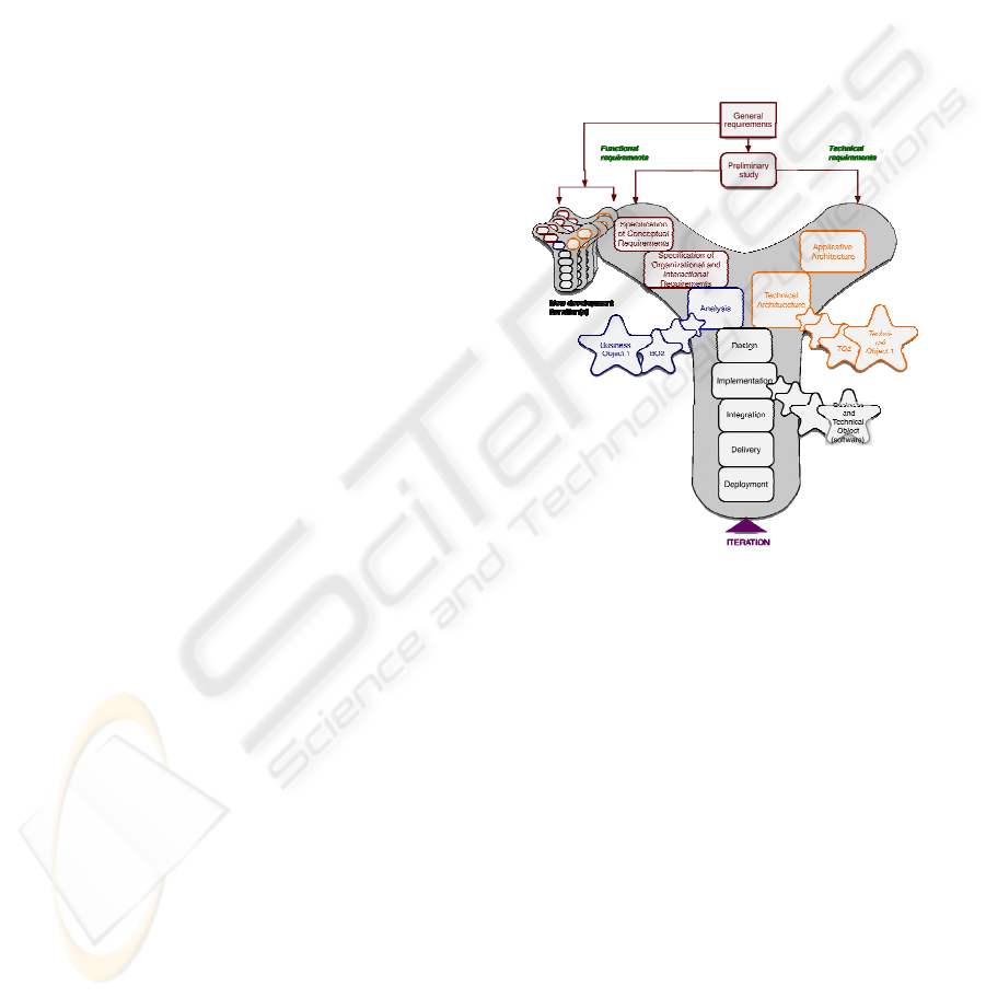
Symphony is organized into three design
branches, similarly to 2TUP, into a Y-lifecycle. The
whole lifecycle is applied for each functional unit of
the system under development (see below):
– The functional (left) branch corresponds to the
traditional task of domain and user requirements
modelling, independently from technical aspects,
– The technical (right) branch allows developers
to design both the technical and applicative
architectures. It also federates all the constraints
and technical choices with relation to security,
pervasiveness, load balancing…
– The central branch integrates the technical and
functional branches into the design model, which
merges the analysis model with the applicative
architecture and details traceable components.
Organization of phases in Symphony is summarized
in Figure 1. For the sake of conciseness, we will
only cover in this section a few aspects of a system’s
design (functional branch) through the Specification
and Analysis phases of the extended Symphony
process.
Figure 1: Symphony design phases.
All phases aim at refining models and scenarios
previously outlined. SE and HCI-oriented activities
are realized in parallel, by design actors specialized
either in Software Engineering or Human-Computer
Interaction. However, both may collaborate in order
to ensure consistency of adopted design options, as
detailed in (Juras et al., 2006b). One will note that
mappings between models exist but are not
described in this paper.
3.2 Case Study
We chose to address a well-known problematic
encountered by real estate agents when making an
inventory of fixtures: the scarcity of data available to
evaluate a housing. Indeed, most of real estate
business processes feature basic computerization:
specifically, details about damages are in most cases
lay out as paper forms and textual descriptions.
ICEIS 2007 - International Conference on Enterprise Information Systems
38
Such data is often insufficient when the real
estate agent needs to evaluate the evolution of a
specific damage or wearing out from one occupation
to the next, especially when this is a contentious
issue between the tenants and the expert or the
landholder.
One solution would consist in allowing the agent
to visualize directly the past and current states of the
premise, using visual cues to signal elements that
need special attention. An Augmented Reality
interface comes to mind when it comes to designing
such a system.
In the following sections, we detail the
development process we adopted for this
application.
3.3 Specification of Conceptual
Requirements
As a prologue to the Specification of Conceptual
Requirements phase, the Preliminary study
essentially deals with splitting up the system
requirements into independent functional units:
Business Processes (i.e., a Business Process can be
considered as a collection of activities taken as a
response to a specific type of input or event and
produces an output of value for the process’ client).
Each is assigned a whole iteration of the Y-lifecycle
and development priorities. Actors (e.g., landholder,
expert, tenants) interacting with the Business
Process are also identified.
During the Specification of Conceptual
Requirements phase, Business Processes are
described in terms of nominal scenario and high-
level sequence diagrams where only actors and
Business Process are represented (i.e., there s no
decomposition of the system yet). We shall focus in
this paper on the “Management of inventories of
fixtures” Business Process.
Business Processes are then refined so as to
identify uninterrupted exchanges between actors and
the Business Process. Such units constitute Business
Processes Components(BPC), which are themselves
described using scenario and sequence diagrams.
These descriptions include alternative scenarios
(extensions of the nominal scenario).
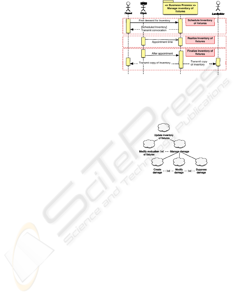
Figure 2: Sequence diagram for the Manage Inventory of
fixtures Business Process.
Successive refinements of the “Management of
the inventories of fixtures” Business Process have
led to identifying the “Realize an inventory of
fixtures” Business Process Component (
Figure 2).
Figure 3: Extract from the task tree for the inventory of
fixtures application.
Parallel to the construction of sequence diagrams
during the Specification of Conceptual
Requirements phase, task trees (Paternó, 2003)
describe abstract user tasks, for each Business
Process and BPC, that is without mentioning actual
device used or modalities such as text, speech,
pointing…
Figure 3 features an extract from the
general task tree that focuses on the tasks involving
the manipulation of the “Damage” concept. Tasks
are ordered into a hierarchy of abstraction, with the
lowest task representing refinement (and successive
reification steps) of parent tasks. The “|=|” operators
linking tasks at a same abstraction level indicate
alternatives for the user. One will note that the task
tree presented in
Figure 3 does not yet feature details
on how the damages are supposed to be
manipulated.
INTERACTIONAL OBJECTS: HCI CONCERNS IN THE ANALYSIS PHASE OF THE SYMPHONY METHOD
39
3.4 Specification of Organizational and
Interactional Requirements
3.4.1 Organizational Requirements
During this activity, each Business Process
Component is further refined into activity diagrams
showing internal actors (for example, the Expert)
and their interactions with the system and the
external actors (for example, the tenants). This
allows identifying manual and computerized tasks.
The latter are then generalized into Use Cases.
Finally, all identified Use Cases are organized
into logical packages usually representing the
Business Process Component (
Figure 4).
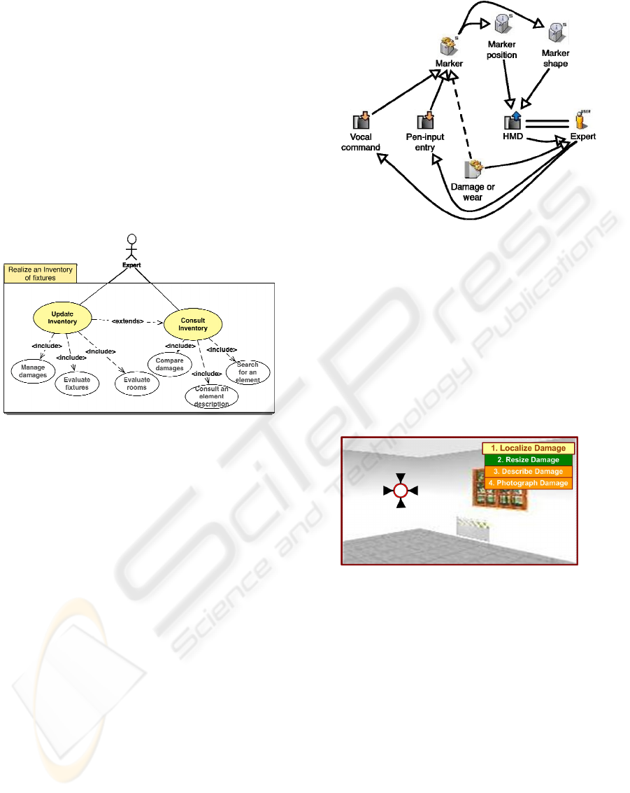
Figure 4: Organization of Use Cases into packages.
3.4.2 Interactional Requirements
The Interactional Requirements refines abstract user
task trees into concrete tasks, thus detailing device
and interaction languages (e.g., vocal commands,
gesture input…) manipulated by the users. Usability
concerns are also addressed during this phase.
Additional models help describe and design the
envisaged interaction, depending on the complexity
of the future system’s interface. Our case study
featuring an Augmented Reality interface, we resort
to ASUR models (Dubois et al., 2002) to assist the
design of interaction. ASUR essentially allows the
designer to describe device, mechanical relations
between device, real objects used to interact with the
system, users and numerical objects used as virtual
representations of real entities. Relations traced
between these concepts finalize the representation of
the system’s Human-Computer Interaction. Figure 5
thus details parts of the interaction technique used
for the task “Manage Damage” in
Figure 3.
Figure 5: ASUR model as a representation of the task
"Manage Damage”.
In the figure above the user, identified as the
Expert, is wearing a Head-Mounted Display (“==”
relation) which provides information (Æ relation
symbolizes physical or numerical data transfer)
about the position and shape of a Marker virtual
object. The Marker is a numerical representation (“--
>” relation) of a physical Damage in the physical
world. The Expert can interact with the Marker
object using Vocal command and Pen-input entries.
Figure 6: Interface prototype as projected on the Head-
Mounted Display.
Figure 6
represents an interface prototype
deduced from both the task tree described in
Figure 3
and the ASUR diagram illustrated in
Figure 5, as
should be displayed on the Head-Mounted Display.
The Marker object indeed helps the user identifying
damages (possible actions are described in the top-
right menu) while walking around the premise.
3.5 Analysis
This phase is quite activity-dense in the Symphony
method. Two types of studies are carried out:
structural (static) and dynamic analysis. The latter
consists in refining the Use Cases into detailed
scenarios and sequence diagrams (similarly to the
ICEIS 2007 - International Conference on Enterprise Information Systems
40
process described in the Rational Unified Process),
in order to identify logic entities: Business Objects.
The dynamic analysis only allows outlining the
services (i.e., the interface) that these entities are
supposed to provide, for example: adding a Marker
object, defining its properties…
During the structural analysis, the Business Objects
identified are expounded in terms of Interface,
Master, Part and Role classes and then organized.
We describe in the following paragraphs such
activities.
Symphony conceptualizes the system as an
assembly of independent and interconnected
Business Objects. This guarantees a modularity of
specifications and encourages their reuse.
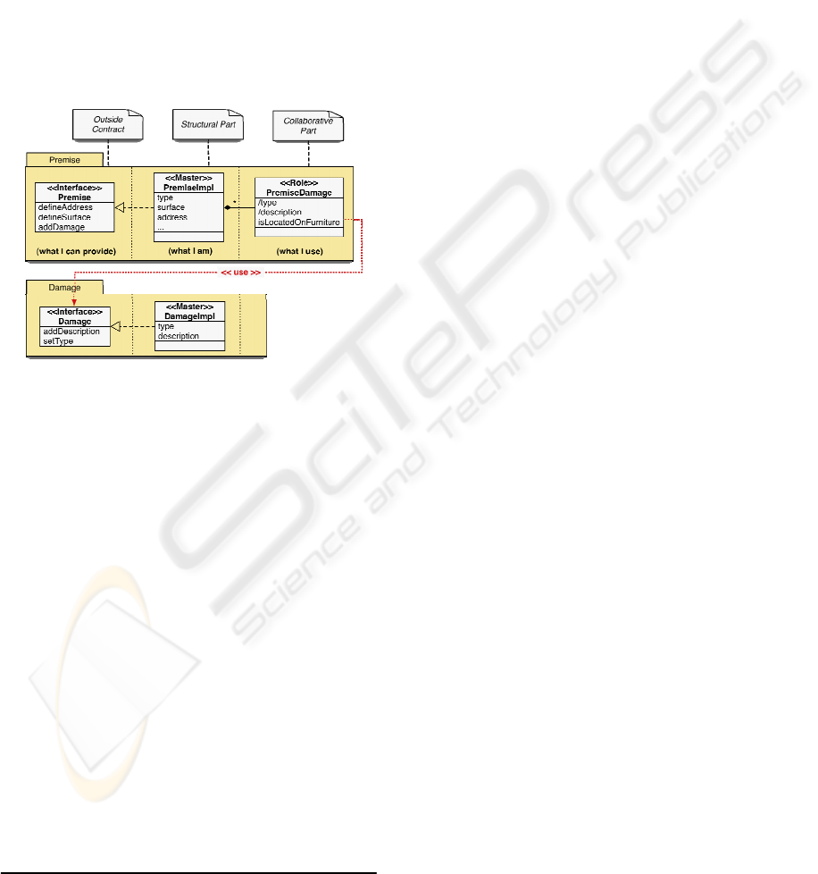
Figure 7: Example of organization between two Business
Object.
Figure 7
presents an example of Business Object
as described during the Analysis phase. One will
note its representation as a tripartite UML package,
into which classical UML stereotyped classes are
defined. The three parts of the Business Object are
conceptually analogous to that of a UML
component
1
. They are composed of:
An outside contract, into which an Interface
class describes the services that can be provided by
the object. For example, the Premise Business
Object can be required to define its address, its
surface or add a damage description,
A structural part, composed of two types of
classes: the Master class, which is a central,
autonomous part, which keeps all the knowledge
about the object’s manipulations, and implements
the Interface ; if needed a Part class (in Figure 8,
the “Localization” class) may complement the
1
UML superstructure – version 2.0 - http://www.omg.org/cgi-
bin/doc?formal/05-07-04
Master class in order to structure its attributes and
highlight key concepts of the Master class.
A collaborative part, where Role classes
feature service providers for the client object (i.e.,
another Business Object) and their adaptation to the
object’s requirements. In Figure 7, the
“PremiseDamage” role is in fact an adaptation of a
generic “Damage” Business Object. The slash-
prefixed attribute “type” describes a concept derived
from the “Damage” object, while the
“isLocatedOnFurniture” attribute represents a notion
proper to the “PremiseDamage” role.
Amongst the different relation types which
enable the designer to organize Business Objects,
the “use” relation, allows developers to represent the
adaptation between a given Business Object and its
role as another’s collaborator (i.e., an object able to
provide services defined into the “Role” class).
Figure 7 illustrates such an organization between
Business Objects, in which the “PremiseDamage”
role’s adaptation of the “Damage” Business Object
is clearly represented.
The interactional aspects of the Analysis phase
are treated in current versions of the Symphony
process as an unspecified technical layer, usually
using applicative architectures such as Struts. We
address the problematic of a more structured
approach to interaction design in the following
paragraphs.
4 INTERACTIONAL OBJECTS
AND CONCEPT MAPPING
4.1 Interactional Concepts
The decisions taken during the specification phases
contribute to constructing an interactional space, as
opposed to the traditional business space. Indeed, we
saw in the previous section that the elaboration of
the human-computer interaction generates new
concepts that need to be integrated into the system
(e.g., the Marker object as a representation of a
Damage). These concepts should facilitate co-design
between SE and HCI developers, as well as reuse
and generation efforts already explored for the
business space. Additionally, they emerge from
interactional diagrams such as ASUR or more
implicit notions that do not appear in these models.
In that respect, we identify three cases:
Explicit mapping: Some concepts, which are
represented in the interaction diagrams previously
elaborated (e.g., see
Figure 5), are mappings of
INTERACTIONAL OBJECTS: HCI CONCERNS IN THE ANALYSIS PHASE OF THE SYMPHONY METHOD
41
business concerns into the interactional space: for
example, a “Marker” is a mapping of the “Damage”
notion. One will note that these mappings translate
properties from Business Objects into wholly
different modalities: for example, the type of
damage (wearing out or alteration) is represented by
different marker shapes and/or colours.
Implicit mapping: Other concepts emerge from
implicit aspects of the interaction diagrams. For
example, in order to show the “Marker” objects to
the user, it is necessary to maintain a numerical
representation of the premise (a 3D mesh, or even a
simple 2D plan) where the markers will be
positioned. However, the numerical representation
also corresponds to the “Premise” concept
introduced in the business space.
No mapping: Finally, other aspects of the
interactional space are neither represented in ASUR
diagrams nor in the business space. For example, it
is necessary to identify the user’s position and
orientation into the premise (in fact, of the numerical
representation of the premise, see above) using
passive sensors (GPS positioning, gyroscopes,
triangulation… that were not represented in the
ASUR diagram, essentially because they are
common to most Augmented Reality systems).
Defining the user’s position in the numerical world
is necessary so as to display the correct virtual point
of view on the HMD’s screens. However, this
concept of “Avatar” has no equivalent into the
business space, as there is no to identify the
application’s current user (i.e., the Expert), at least
when considering the “Realize an Inventory of
Fixtures” Business Process.
From a practical point of view, the mappings
between the interactional and business spaces would
be more clearly and easily expressed if the same
models structures both spaces. Therefore, a set of
evolutions needs to be undertaken concerning the
Analysis phase, in order to take into account the
models described during the Specification of
Interactional Requirements phase, on one hand. On
the other hand, it is also necessary to combine HCI
models with the technical, Software Engineering-
oriented aspects usually described during the
Analysis phase, in order to provide a common
ground for describing HCI and SE concepts. The
following paragraphs describe such addenda.
4.2 Interactional Objects
In analogy with Business Objects, which constitute a
conceptual view of the system’s functional aspects,
within a business space, we introduce the concept of
Interactional Objects, which correspond to a more
technical or programmatic view of the system’s
interactional aspects, within an interactional space.
They are technology-independent models that should
not put excessive constraints on the development
practices of HCI designers.
As a comparison, one will note that other
notations aim at structuring the interactional space.
For instance, as an extension of the ASUR model for
Augmented Reality, (Dubois et al., 2006) proposes a
participatory design process and ASUR-IL: a
transformation of ASUR components into MVC-
based software units, which also allows for rapid
prototyping of the system. However, this approach
does not provide any formalization of the design
process or mapping with SE concepts. Also, apart
from restraining development to MVC-based
architectures, reuse is not addressed in this work.
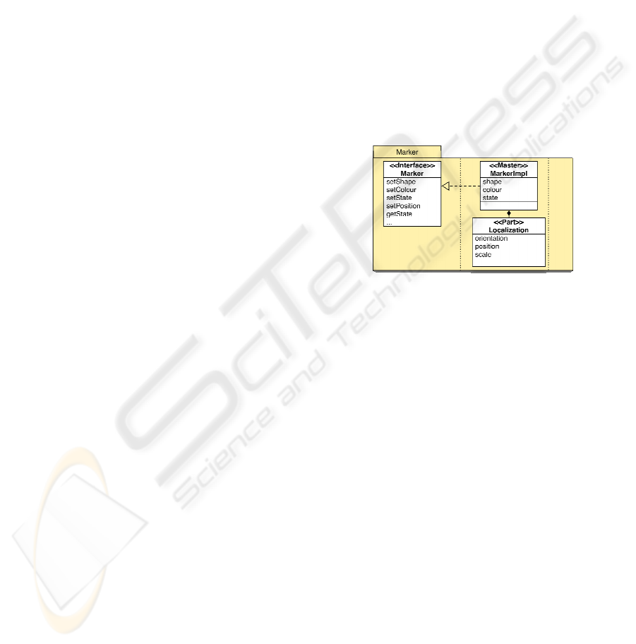
Figure 8: Interactional Object example
Despite the distinct conceptual spaces to whom
they are attached, Interactional Objects and Business
Objects are structurally similar: they are described as
tripartite UML packages as an incentive to build
interactional components. Using Roles allows the
developers to adapt these components to applicative
concerns. Figure 8 presents the Interactional Object
“Marker”, which corresponds to the concept detailed
in the above sections. It is thus possible to define the
Marker’s shape, colour, position, orientation or
current state (locked or unlocked)…
Additionally, Interactional Objects can be
organized similarly to Business Objects, through the
“use” relation. As a rule, these relations can only
bind Symphony Objects from the same conceptual
space (i.e, interactional or business).
ICEIS 2007 - International Conference on Enterprise Information Systems
42
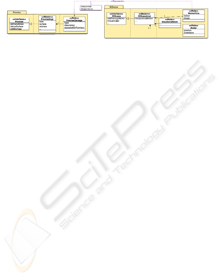
Figure 9: Example of adaptation between Interactional Object and Business Object.
4.3 Adaptation Modelling
In order to illustrate the representation of business
concepts into the interactional space and realize
mappings between both spaces, we introduced a new
“Represent” relation.
Figure 9 illustrates the use of
this relation, which binds the “MarkerRole” class to
the “PremiseDamage” role: in our application a
graphical marker is indeed responsible for
representing the “Damage” concept, which is itself
adapted to the “Premise” business-specific context.
The adaptation between the interactional and
business spaces occurs in two steps:
Signature modelling: the adaptation realized
when instantiating the Interactional Object. It is
constituted by the mapping and transformation of
Interactional Object attributes (and, if needed, their
instanciation) to their Business Object counterpart.
For instance, the “Marker” Interactional Object is
adapted to the inventory of fixtures’ problematic
(that of a Damage Marker) by assigning it a specific
colour (red) and shape (torus), through the
“Represent” relation. These attributes do not have
specific equivalents in the “PremiseDamage”
Business Object, but correspond to the signature of
this specific MarkerRole-PremiseDamage relation.
State mapping correspond to the mapping of
interactive events’ semantic into the business space,
if it implies a modification of its corresponding
Interactional Object’s state. For instance, if a
“DamageMarker” object (i.e., a Marker adapted to
signalling damages through its static modelling
specialization, see above) is set into its “locked”
state, the corresponding “PremiseDamage” object
must be validated (i.e., saved into the real estate
agency’s database). State mapping can thus be
represented as statechart diagram mappings with
user events triggering transitions. For the sake of
conciseness, we shall not treat the specifics of these.
mechanisms in this paper.
In the next section, we explore how the use of
Interactional Objects and “Represent” relations eases
the design “for reuse” of Interactional Components.
5 DESIGN “FOR REUSE”
While system modularity is central to the Symphony
method, it is less trivial to organize development
with reuse in mind. This is especially true for
business components, which although theoretically
sound, are in practice seldom developed or seldom
reused as each project features a very specific
approach to business.
However, by their very nature, interactional
components are often reused in different
applications. For instance, most of the Interactional
Objects we designed (SituationalMesh, Marker,
Avatar and 3DScene…) are recurrent concepts
found in Augmented Reality systems.
Although we do not intend to detail design time
aspects of Symphony, suffice it to say that
Interactional Objects can be considered as logical
abstractions from technical implementations, or
Interaction Components. For instance, the
Interaction Objects in the prototype we designed for
the Augmented Inventory of Fixtures features an
OpenGL implementation of our Interactional
Components that was quite effortless to develop. In
that respect, it is possible to build libraries of
reusable Interactional Objects as abstractions from
technical component libraries.
Moreover, aside from building single-element
libraries, Interactional Objects can be provided into
organized sets, for example an “Augmented Reality
set” that includes commonly used Interactional
Objects such as “SituationalMesh”, “Avatar” and
“3DScene”, into which common services are
described (e.g. adding an object into the scene,
localizing…). Such elements could for example be
reused for the MEMO system described in (Bouchet
et al., 2004), for which a user wearing a HMD and
using vocal commands may create virtual post-its
that may be disposed anywhere (for instance, close
to an interesting spot in a city) for other MEMO
users to see (when visiting the aforesaid city).
Thus, Interactional Objects encourages the
development of reusable components and sets of
components for human-computer interaction.
INTERACTIONAL OBJECTS: HCI CONCERNS IN THE ANALYSIS PHASE OF THE SYMPHONY METHOD
43

6 CONCLUSION AND FURTHER
WORK
We have introduced in this paper a set of concepts
that allows designers to take into account the design
of the HCI throughout the specification and analysis
phases of a design method: Symphony. While
originally aimed at designing classic systems, HCI
models and processes were integrated into the
specification phases, during a first evolution of the
method, thus permitting the design of Augmented
Reality (AR) interfaces.
As a complement to these efforts, our first
contribution – Interactional Objects –, allows HCI
designers to describe and organize interaction-
specific concepts similarly to current SE practices
for the business space. Our second contribution – the
“Represent” relation –, allows SE and HCI designers
to draw links between the concepts that emerge in
the business and interactional spaces.
Future works include finalizing the Augmented
Inventory of Fixtures application, refining the
method further on and applying it to a variety of
projects, either in terms of domains (airport security)
or type of interface (classical interaction, AR). This
will also enable us to explore the reuse capacities of
Interactional Objects and Interactional Components
for AR as well as enlarge our component repository.
Additionally, we need to explore to what extent
Interactional Objects should be adapted or variable.
Finally, we plan to provide rationale concerning
component choice using patterns, similarly to the
approach described in (Godet-Bar et al., 2006).
Refining the method shall also imply describing
more formally SE and HCI model weaving.
ACKNOWLEDGEMENTS
The authors wish to thank the INPG and the IMAG
federation for their financial support.
REFERENCES
Bouchet, J., Nigay, L., Ganille, T., 2004. ICARE software
components for rapidly developing multimodal
interfaces. In Proc. of the Sixth International
Conference on Multimodal Interfaces, pages 251-258.
Chalon, R., David, B. T., 2004. Modélisation de
l’interaction collaborative dans les systèmes de Réalité
Mixte. In Proc. of the ACM Conference IHM’04,
pages 37-44. ISBN : 1-58113-926-8. In French.
Constantine, L., Biddle, R., Noble, J., 2003. Usage-centred
design and Software Engineering : Models for
integration. In Proc. of the IFIP TC13 workshop on
Closing the gaps: Software Engineering and Human-
Computer Engineering. Borup Harning & Jean
Vanderdonckt eds.
Dubois, E., Nigay, L., Troccaz, J., 2002. Assessing
continuity and compatibility in augmented reality
systems. In UAIS, International Journal on Universal
Access in the Information Society, Vol. 4, pages 263-
273. Springer-Verlag.
Dubois, E., Gauffre, G., Bach, C., Salembier, P., 2006.
Participatory design meets Mixed Reality design
models : Implementation based on a formal
instrumentation of an informal design approach. In
CADUI’06, Computer-Aided Design of User
Interfaces, pages 75-88. Springer-Verlag.
Godet-Bar, G., Dupuy-Chessa, S., Nigay, L., 2006.
Towards a system of patterns for the design of
multimodal interfaces. In CADUI’06, Computer-Aided
Design of User Interfaces, pages 27-40. Springer-
Verlag.
Gulliksen, J, Göransson, B., 2005. Usability design :
Integrating user-centred systems design. In The System
Development Process tutorial at CHI’2005, USA.
Hassine, I., Rieu, D., Bounaas, F., Seghrouchni, O., 2002.
Symphony : a conceptual model based on business
components. In SMC’02, IEEE International
Conference on Systems, Man, and Cybernetics, Vol. 2.
Jacobson, I., Booch, G., Rumbaugh, J., 1999. The Unified
Software Development Process. Addison-Wesley.
Juras, D., Rieu, D., Dupuy-Chessa, S., 2006. Vers une
méthode de développement pour les Systèmes Mixtes.
In INFORSID’06, Actes du 24
ème
Congrès
Informatique des Organisations et Systèmes
d’Information et de Décision, pages 33-48. In French.
Juras, D., Rieu, D., Dupuy-Chessa, S., Front, A., 2006.
Conception collaborative pour les Systèmes Mixtes. In
Revue Génie Logiciel nb.77, GL-IS, pages 31-36. In
French.
Lim K. Y., Long J., 1994. The MUSE method for usability
engineering, Cambridge University Press.
Paternò, F., 2003. The handbook of task analysis for
human-computer interaction. Chapter
ConcurTaskTrees: An Engineered Notation for Task
Models, pages 483-503. Lawrence Erlbaum
Associates.
Sousa, K. S., Furtado, E., 2003. An approach to integrate
HCI and SE in requirements engineering. In Proc. of
the IFIP TC13 workshop on Closing the gaps:
Software Engineering and Human-Computer
Engineering. Borup Harning & Jean Vanderdonckt
eds.
Tarby J.C., Barthet M.F., Analyse et modélisation des
tâches dans la conception des systèmes d’information :
la méthode Diane+. In : Analyse et conception de
l’IHM, pp 117-144, Hermès, 2001. In French.
ICEIS 2007 - International Conference on Enterprise Information Systems
44
