MODELING USER INTERFACES WITH THE XIS UML
PROFILE
Carlos Martins
Universidade da Madeira, Campus da Penteada, Funchal, Portugal
Alberto Rodrigues da Silva
INESC-ID & Instituto Superior Técnico, Rua Alves Redol, nº9 – 1000-029 Lisboa, Portugal
Keywords: Modeling User Interfaces, Model Driven Development (MDD), Unified Modeling Language, UML Profile.
Abstract: This paper discusses different User Interface design approaches. We describe how to design user interfaces,
based on a MDD approach, by applying the XIS language. XIS is a coherent UML profile focused on model
interactive systems. XIS integrates best practices and principles of the MDA/MDD paradigm to improve the
User Interface design, such as separation of concerns, model-to-model and model-to-code transformations.
In that way, we discuss some issues regarding the transformation processes, from XIS-based models into
software systems artifacts.
1 INTRODUCTION
A relevant area of interest of the Human-Computer
Interaction and Software Engineering communities
is the specification, design and development of
interactive systems, in particular, in what concerns
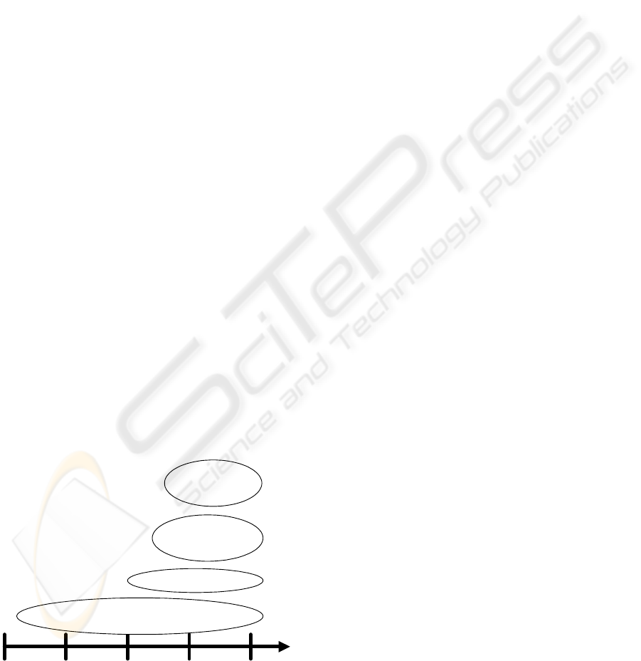
the User Interfaces (UI) design. Figure 1 suggests
the four main approaches for UI design, namely
based on: (1) UI builder tools; (2) UI sketching
tools; (3) XML languages; and (4) UML models.
1985 1990 1995 2005
2000
V I S U A L B A S I C
S I L K D E N I M
A
U
I
M
L
X
I
M
L
U
I
M
L
XFORMS
W I S D O M
U
X
U M L i
O
V
I
D
U W E
T
R
I
P
O
D
D E L P H I
V
I
S
U
A
L
S
T
U
D
I
O
. . .
. . .
. . .
. . .
Figure 1: UI design approaches.
The “UI builder tools” approach is a very
popular and productive way to visually design and
build UIs. These tools allow UI gadgets and
components visual placement and configuration to
create windows and dialog boxes, as well as allow
their behavior definition (commonly by
programming callback methods in target
programming languages, such as C++, C#, Java,
ObjectPascal). This approach is supported by
common IDE, such as Visual Basic, Delphi, Visual
Studio.NET or Eclipse. An important reason for the
success of these UI builders has been that they use
graphical means to express graphical concepts (e.g.,
interface layout). By moving some aspects of user
interface implementation from conventional code
into an interactive specification system, make these
aspects of interface implementation to become
available to those who are not conventional
programmers. This has allowed visual design
professionals to become more involved in creating
the appearance of interfaces. Even the programmers
benefited, as the speed of building was dramatically
reduced. On the other hand, this approach is
considered too “low-level”, and also the produced
UIs are targeted to a specific UI framework and
platform (e.g., Desktop, Mobile, Web-based) and so,
it does not allow flexible and platform-independent
deployment.
98
Martins C. and Rodrigues da Silva A. (2007).
MODELING USER INTERFACES WITH THE XIS UML PROFILE.
In Proceedings of the Ninth International Conference on Enterprise Information Systems - HCI, pages 98-104
DOI: 10.5220/0002388800980104
Copyright
c
SciTePress
The “UI sketching tools” approach consists in
designing user interfaces prototypes through
sketching techniques (Landay and Mayers, 2001,
Newman et al., 2003). These tools try to recognize
the sketchs and produce specific user interfaces;
some of them can be targeted to different UI
platforms automatically. Designing sketchs enforces
the designer creativity, but the task of recognition of
the sketch components is not easy, so the generation
tends to be hard to produce or erroneous.
The third approach uses UI XML-based
languages. In this approach the UI is specified
according a formal XML language, with the
corresponding benefits, such as automatic syntax
validity, portability, and UI rendering for different
target UI platforms. There are many UI XML based
languages (Souchon and Vanderdonckt, 2003) like
UIML (Abrams et al., 1999), XIML (Puerta and
Eisenstein, 2002), XForms (W3C, 2006), or AUIML
(Azevedo et al., 2000). For example, the OVID to
AUIML proposal intends to link the OVID (Object,
View and Interaction Design) method with the
AUIML language. OVID methodology is a set of
techniques for designing UI. The goal of OVID to
AUIML project is to generate specific UI to each
platform from an OVID UML diagram. It is
necessary to construct specific renderers for each
XML abstract language and for each UI platform.
Finally, the fourth approach is inspired in the
MDD (Model Driven Development) paradigm and
the MDA (Model Driven Architecture) (OMG). This
approach consists in designing UI UML-based
models, from which generative code techniques are
applied to automatically produce UI code and other
software artifacts. MDD paradigm has the goal to
describe the system functionalities using a set of
models, shifting the software development focus
from code to models artifacts. An UI model is a
representation of how the end-users interact with the
software system. MDD paradigm intends to create
automatic mechanisms to generate software artifacts
from these models.
MDD transforms platform independent models
(PIM) into platform specific models (PSM). PIM
models are abstract models that describe the
structure and function of a system in a platform-
independent way. On the other hand, PSM models
are clearly platform-specific, and so are models
designed at a lower level of abstraction.
In this paper we analyse and discuss several
initiatives in the scope of the fourth referred
approach, i.e., the UI design based on MDD
approach. In general, it is important to use a formal
and a platform independent way to design UIs. It
must be formal to make it possible to support code
generative mechanisms, although more formalism
implies usually less flexibility. It can be platform
independent to make possible to generate artifacts
for different platforms. Another important
characteristic is the rastreability of the several steps
of the generative process, as well as the facility to
introduce reverse engineering mechanisms.
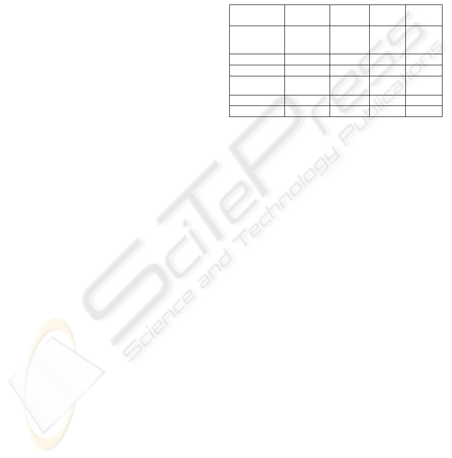
Table 1: Comparison between the different approaches.
Approach
Item
Interface
Builder
XML
Based
Sket-
ching
MDD
Basic
Concepts
Toolbox
of UI
Controls
XML
langua-
ges
Sketchs Models
Formalism
+ + + - +
Flexibility
+ + + + + +
Platform
Independent
- + + + + +
Rastreability
NA + + + + +
Productivity
+ + - + +
Table 1 presents a brief comparative analysis of
the different approaches, showing the respective
benefits and limitations.
This paper describes the scope, principles, and
main elements of the XIS profile. Section 2
discusses related work. Section 3 briefly introduces
the context of the ProjectIT research program, in
which the XIS is defined and applied. Section 4
overviews the principles to model user interfaces
applying the XIS profile, and introduces the
“MyOrders” case study that will be used for
supporting the respective explanation. Section 5
explains the generative process and the model-to-
code transformations to generate specific interactive
systems prototypes. Finally, section 6 summarizes
the key points of this paper.
2 RELATED WORK
Andersen discussed several important aspects to be
considered in the model-based UI design (Anderson,
2000), namely: (1) models must be easily drawn by
hand (without any electronic tool) to easily improve
the discussion of ideas; (2) the models must be
easily implemented by an electronic tool; (3) the
models must be visually clean; (4) the elements of
the model must be sufficiently clear and distinct to
avoid confusion or misinterpretation; they must
identify the abstract role they represent; and (5) it
must be possible to visually highlight that one
element is part of another element.
MODELING USER INTERFACES WITH THE XIS UML PROFILE
99
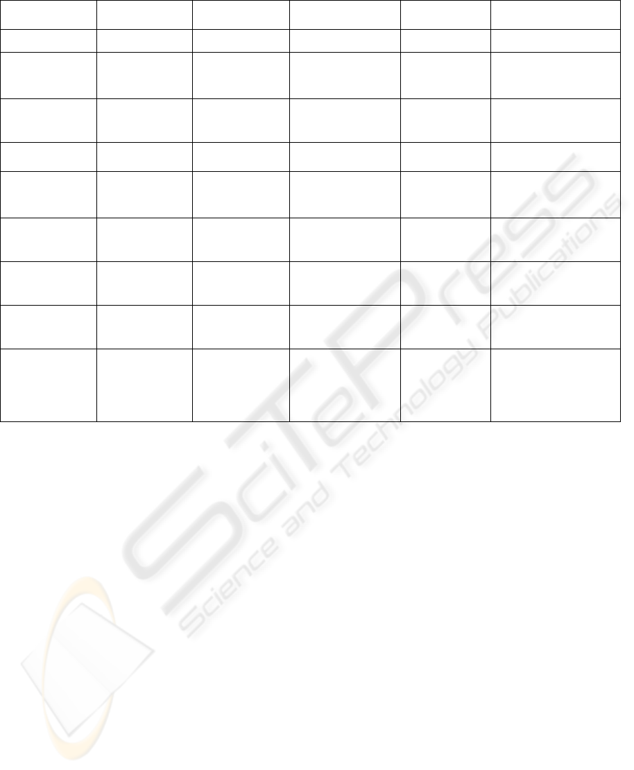
Table 2: Comparison between different initiatives based on the MDD approach.
Initiative
Item
UX
UMLi
UWE Wisdom XIS
Domain Models
No Domain Model
Conceptual Model No Entities View
Navigation
Models
Participants
Diagram,
State Machine
Activity
Diagram
Navigation Model,
Storyboard Model
Presentation
Model
NavigationSpace
View
Content Models
No
User Interface
Diagram
Abstract User
Interface Model
Canonical
Abstract
Prototypes
InteractionSpace View
Easily drawn by
hand
+ +
- - +
Visually Clean /
Facility to read
+
(Not include
content model)
-
+ + + +
Allow the
concept of
containment
«Screen»
«Compartment
»
«Free
Container»
«Container»
«UI View»
«Presentation
Class»
«Interaction
Space»
«Contains»
«XisInteractionSpace»
«XisInteractionCompo
siteElement»
Some concern
about size and
position
- + + + + + + +
Uses Platform
Independent
Models
+ + + + + + + +
Generation to
specific
platforms
Java Struts
Framework.
Possibility to
generate only
Web platforms
Possibility to
generate several
platforms
Possibility to
generate only Web
platforms
Possibility to
generate
several
platforms
Possibility to generate
several platforms (e.g.
Winforms.NET and
ASP.NET)
Table 3 summarizes the main concepts and
features of different proposals of UI design
regarding the MDD approach, in particular: User-
Experience (UX) (Kozaczynski and Thario, 2002),
Wisdom (Nunes and Cunha, 2000), UMLi (Silva and
Paton, 2000), UWE (Hennicker and Koch, 2001)
and XIS.
The UX approach defines modeling elements for
the navigation design and discusses the
transformations of UX UML models into code-level
models for specifically the Java Struts framework.
The Wisdom and the UX approaches represent
quite well navigation aspects with some similarities
with our NavigationSpace View, but don’t define
any model to represent each node of the user
interface in an abstract way as we propose in XIS.
The Wisdom approach aims to maintain
synchronization between Wisdom and Canonical
Abstract Prototypes (Constantine et al., 2003), which
represent each node of the user interface in an
abstract way.
The UMLi approach proposes a profile to
capture the conceptual, presentation and behaviour
aspects of systems.
The UWE approach focuses particularly on
modeling Web systems. The proposals in UMLi and
UWE, for the presentation design, have some
similarities with our InteractionSpace View.
The OVID approach aims to link the OVID
UML models to the AUIML XML based language.
Few of these approaches are making real efforts
to develop UML tools to support the design of
models with generative techniques. Additionally,
XIS differentiates itself from these proposals
because it considers the trade-off between simplicity
(a driver that justifies keeping models at the PIM
level) and productivity (a driver that justifies the
adoption of models transformation techniques) a
crucial issue, unlike any of those proposals.
3 THE PROJECT CONTEXT
As a result of the experience gathered from previous
research and practical projects, the Information
Systems Group of INESC-ID (http://gsi.inesc-id.pt/)
started an initiative in the area of requirements
engineering and model driven development, named
ProjectIT (Author, October 2004). One of the results
of this project is a UML profile, called XIS (short
name for “eXtreme modeling Interactive Systems”).
ICEIS 2007 - International Conference on Enterprise Information Systems
100

The XIS UML profile is a set of coherent UML
extensions that allows a high-level, visual modeling
way to design interactive systems. There are three
main concerns that are captured through
complementary views, namely around the entities,
use-cases, and user-interfaces views. Entities View
contains the common domain model as well as a
model that captures business entities (i.e., logical
representation of “high-level” entities, defined on
top of the domain entities). The design of business
entities is an optional decision although it is
recommended. On the other hand, Use-cases View
contains the actors model and, in an optional way, an
extension of use cases model that describe how use
cases can be related with actors and with business
entities. In these models the designer captures and
organizes the system’s functional requirements
according a pragmatic and simple approach. Finally,
the User-interfaces View contains two high-level
platform-independent and complementary models:
the NavigationSpace and the InteractionSpace
models. In this paper we will discuss in more detail
the User-interfaces View.
4 MODELING UIS WITH XIS
This section describes the scope, principles, and
main elements of the XIS profile. XIS adheres
strongly to the “separation of concerns” principle,
and consequently proposes an integrated set of
views, namely the entities, use-cases and user-
interfaces views. In addition, XIS promotes extreme
modeling by providing a roadmap that designers can
follow as well as model-to-model transformation
templates both to assist and to accelerate their tasks.
The second version of the XIS UML profile is a
coherent group of UML extensions that allows us to
model interactive systems according to the ProjectIT
approach. In spite of XIS being a key element of
ProjectIT and supported by the ProjectIT-Studio
tool, it should be emphasized that XIS is just an
UML profile, and so it can be used and supported by
different CASE tools.
There are two important models to represent UI.
The first one is used to represent navigation between
the different interaction spaces. A navigation model
is useful to support the documentation of the system
structure giving the chance to easily change and
improve its navigability. The second one is used to
represent the content of each interaction space.
Constantine & Lockwood describes a content model
like an abstract model that shows the intended
contents of a part of a UI (Constantine and
Cockwood, 1999). These contents are interaction
elements of the UI and could be elements like data
elements, containers and action elements (e.g.
commands or operations). The content models are
useful to represent the structure and overall
organization of the UI, without any commitment to
choose any particular GUI control.
The XIS UML profile is a set of coherent UML
stereotypes that allows a high-level, visual modeling
way to design interactive systems. There are three
main concerns that are captured through
complementary views, namely around the entities,
use-cases, and user-interfaces views. The User-
interfaces View contains two high-level platform-
independent and complementary models: the
NavigationSpace View and the InteractionSpace
View. The NavigationSpace View defines the top-
level navigation map, which is a directed graph
where the nodes are references for Interaction
Spaces and the links represent the transitions
between these Interaction Spaces, typically triggered
by end-user operations. The NavigationSpace View
defines the navigation that can occur between any of
the interaction spaces. The InteractionSpace View
defines the user-interface interaction elements that
are contained in each interaction space; this view
can also specify access control between actors and
user-interface elements.
For better understanding and simplicity of the
explanation we use a tiny case study, the “MyOrders
System” (see table bellow).
Table 3: Case Study – My Orders.
A Tiny Case Study – The MyOrders System
MyOrders is a system that allows keeping relevant
information for every organization. The MyOrders
system manages business entities such as products,
suppliers, customers and orders.
There is information associated with each entity; for
instance, a product has a name, a price and an
indication of how many units are in stock. An order
can cover multiple products (i.e., it is not necessary to
create an order for each product to be acquired).
However, the system keeps the information regarding
an order and an acquired product as the “order details”.
A supplier and a customer are third-party entities,
usually companies, which can have multiple affiliates
(i.e., multiple contacts). Additionally, each affiliate is
of a certain type, which is identifiable by its name.
There are some differences between a supplier and a
customer: (1) a supplier cannot place orders, as it is
only responsible for supplying products, not for
consuming them; (2) a customer can only acquire
products by placing an order; […]
MODELING USER INTERFACES WITH THE XIS UML PROFILE
101
4.1 NavigationSpace View
The main purpose of the NavigationSpace View is to
identify the different interaction spaces and describe
the navigation flow between them. This view is
useful to support the documentation of the system
structure, giving the chance to easily change and
improve its navigability.
XisInteractionSpace
- FirstByDefault: boolean
XisNa v igationAssociation
- rol eName: stri ng
*
*
*
contains
0..1
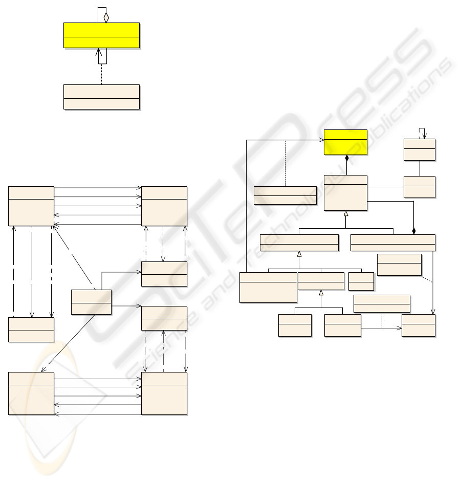
Figure 2: XIS NavigationSpace View Metamodel.
Figure 2 illustrates the NavigationSpace View
metamodel.
«XisInteractionSpace»
Products_ISpace
«XisInteractionSpace»
Product_ISpace
«XisInteractionSpace»
Suppliers_ISpace
«XisInteractionSpace»
Main_ISpace
«XisInteractionSpace»
Customers_ISpace
«XisInteractionSpace»
Orders_ISpace
«XisInteractionSpace»
Orde r_ISpace
«XisInteractionSpace»
OrderDetails_ISpace
+Save_Product
«XisNavigationAssociation»
+Save_Order
«XisNavigationAssociation»
+Delete_Order
«XisNavigationAssociation»
+New_Order
«XisNavigationAssociation»
+Select
«XisNavigationAssociation»
+Orders
«XisNavigationAssociation»
+Select
«XisNavigationAssociation»
+New_Product «XisNavigationAssociation»
+Select_Supplier
«XisNavigationAssociation»
+Select_Customer
«XisNavigationAssociation»
+Cancel
«XisNavigationAssociation»
+Select_Product
«XisNavigationAssociation»
+Cancel
«XisNavigationAssociation»
+Delete_Product
«XisNavigationAssociation»
+Cancel
«XisNavigationAssociation»
+Cancel_Order«XisNavigationAssociation»
+Modify_Product
«XisNavigationAssociation»
+Modify_Order
«XisNavigationAssociation»
+Select
«XisNavigationAssociation»
+Canvel_Product«XisNavigationAssociation»
+Customers
«XisNavigationAssociation»
+Suppliers
«XisNavigationAssociation»
+Products
«XisNavigationAssociation»
Figure 3: NavigationSpace View (MyOrders).
The XIS profile defines the following stereotypes
for this view:
XisInteractionSpace: is used to represent an
interaction space that is visited by the user during
the user-interface navigation and is responsible for
receiving and presenting information to the users;
XisNavigationAssociation: indicates navigation
between two interaction spaces showing the
direction of the transition.
Using this model we can describe the navigation
flow between different XisInteractionSpaces. We
defend that it is not relevant to represent in this view
the UI elements contained in each
XisInteractionSpace.
4.2 InteractionSpace View
The main purpose of the InteractionSpace View is to
describe the contents and the overall organization of
the different Interaction Spaces.
The InteractionSpace View uses some sketching
techniques providing some hints about the size and
relative position of the elements that belong to each
XisInteractionSpace.
Figure 4 illustrates the InteractionSpace View
metamodel.
XisInteractionElement
text: string
posX: int
posY: int
width: int
height: int
XisDomainElement
XisActionElement
actionType: ActionT ype
icon: string
standardAction: StandardAction
sh ort c u t : stri n g
XisOtherElement
value: string
XisElementRight
visible: boolean
active: boolean
XisActor
rol e : stri n g
XisInteractionComposite Eleme nt
compositeElementType: CompositeElementType
XisInteractionSpace
name: string
firstByDefault: boolean
XisInte ractionSimpleElement
XisDataElement
controlType: ControlType
XisDataTable
Query: string
XisEntity
name: string
description: string
XisDomainAssociation
associationName: string
associationRole: string
XisDomainAttributeAssociation
attributeName: string
XisPerformsNavigationAssociation
navigationRole: string
*
0..1
*
1
*
1
*
+parent 1
+child *
*
0..1
0..* 1
*
Figure 4: XIS InteractionSpace View Metamodel.
The XIS profile defines the following stereotypes
for this view:
XisInteractionElement: abstract class, which has
two specializations, describing simple and
composite user-interface interaction elements;
XisInteractionCompositeElement: an UI
composite element, which contains others
XisInteractionElements;
XisDomainElement: an UI interaction element
associated with a XisEntityAttribute from the
Domain View;
XisOtherElement: an UI interaction element that
is not associated in any way with a XisEntity (e.g., a
label or an image);
ICEIS 2007 - International Conference on Enterprise Information Systems
102
«XisInteractionSpace»
OrderDetail_ISpace
«XisActionElement»
OK
«XisInteractionCompositeElement»
Order_Detail
«XisActionElement»
Cancel
«XisDomainElement»
Quanti ty
«XisDomainElement»
Unit_Price
«XisDomainElement»
Discount
«XisDomainElement»
Product_Name
«XisOtherElement»
Titl e
Figure 5: InteractionSpace View – OrderDetail_ISpace.
XisDataTable: an UI interaction element that
contains a table with the result of a SQL query
statement;
XisActionElement: an UI interaction element
which is responsible for invoking an action or an
operation, (e.g., a button or a link);
XisElementRight: is applied to specify access
control between actors and UI interaction elements.
Figure 5 illustrates the OrderDetail_ISpace
XisInteractionSpace for the MyOrders case study.
5 GENERATIVE PROCESS
One of the main features proposed by the MDD
paradigm is the model-to-code transformation.
ProjectIT tool automatically transforms models,
defined according the XIS language, into system
artifacts (e.g., C#, Java or SQL code). So, after the
modeling UI activity, the next step is the code
generation. The generative process uses software
templates to support the generation mechanisms.
Templates are definitions of model-to-model or
model-to-code transformations. A template uses an
approach that is different from that used to write
software code. A template (Parr, May 2004) is an
artifact (e.g. source code file, html file) with built-in
actions that are processed and evaluated by a
template engine, defining a specific transformation.
The architect must define the templates in a
language supported by the template engine. This
template engine receives input models and generates
models or other artifacts.
Before starting the generative process it is
necessary to define the software architecture. In the
ProjectIT, the architecture defines the generation for
a specific platform.
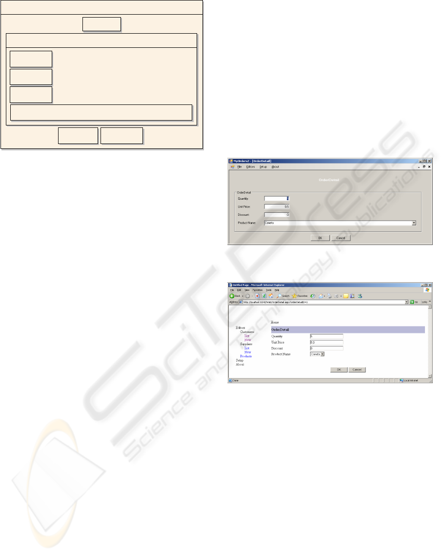
In our work we developed templates to generate
artifacts for two software architectures: (1) Windows
Froms.NET and (2) ASP.NET. We generate several
widgets that can be included in a UI, such as: labels,
text boxes, combo boxes, check boxes, radio
buttons, buttons, links, menus, group boxes, data
grids and tab panels. The widgets are positioned one
in each line starting from top to bottom of the form,
except buttons and links that are positioned nested in
the same line. Menus and tab panels also have
specific positioning rules. We also produced
mechanisms to infer the size of the different widgets
from the domain model.
Figures 6 and 7 are examples of a generated
InteractionSpace View for these two different
platforms: Windows Forms.NET and ASP.NET.
Figure 6: Example of a generated UI (Windows
Forms.NET).
Figure 7: Example of a generated UI (ASP.NET).
6 CONCLUSIONS AND FUTURE
WORK
In this paper, we suggest and compare the four main
approaches of User Interfaces (UI) design such as UI
builder tools, UI sketching tools, XML based
languages and UML based models. Our project is
based on this last approach and it is inspired in the
MDD / MDA paradigm (OMG). This UML based
approach consists in designing UI UML-based
models, from which generative code techniques are
applied to produce UI code and other software
artifacts automatically.
Our initiative uses our XIS UML profile, which
is a set of coherent UML extensions that allows a
high-level, visual modeling way to design interactive
MODELING USER INTERFACES WITH THE XIS UML PROFILE
103

systems. XIS profile is a key element of the
ProjectIT research program and, despite off being
theoretically CASE tool independent, it should be
better understood and applied in its context. The
generative process uses software templates to
support the generation mechanisms. We produced
templates to generate two different specific
platforms: Windows Forms.NET and ASP.NET.
In future work, we shall focus on the
development of these transformation templates. It
would be interesting to improve some aspects of the
generative process, specially those aspects related to
the layout, such as positioning several widgets in the
same line, and generating other new widgets (e.g.
multiline text boxes, list boxes, toolbars, and tree
views). Also it would be interesting to produce
templates to: (1) generate reports, (2) generate other
specific platforms and (3) transform our XIS UML
models into XML based languages, then using
rendering mechanisms it would be possible to
generate others specific platforms.
In conclusion, our paper compares our XIS
initiative with other initiatives based on the MDD
approach. Few of these approaches are making real
efforts to develop UML tools to support the design
of models with generative techniques. Our approach
presents some advantages such as:
(1) use of platform independent models to
specify the system functionalities, making
possible the generation to several specific
platforms;
(2) concern about aspects related with size and
position, which improves the facility to read;
(3) facility to read: our models are visually
clean and easy to read, the elements of the model
are clear and distinct to avoid misinterpretation
improving the discussion of ideas;
(4) focus, not only on the generation of the UI,
but also on the logic of the system.
REFERENCES
Abrams, M., Phanouriou, C., Batongbacal, A. L.,
Williams, S. M. & Shuster, J. E. (1999) UIML: An
Appliance-Independent XML User Interface
Language. World Wide Web Conference.
Anderson, D. J. (2000) Extending UML for UI. Tupis
2000 Workshop - Towards a UML Profile for
Interactive Systems Development.
Author (October 2004) Blind Reference.
Azevedo, P., Merrick, R. & Roberts, D. (2000) OVID to
AUIML - User-Oriented Interface Modelling. Tupis
2000 Workshop - Towards a UML Profile for
Interactive Systems Development.
Constantine, L., Windl, H., Noble, J. & Lockwood, L.
(2003) From Abstraction to Realization: Canonical
Abstract Prototypes for User Interface Design.
Constantine, L. L. & Cockwood, L. A. D. (1999) Software
for Use, ACM Press/Addison-Wesley Publishing Co.
Hennicker, R. & Koch, N. (2001) Modeling the User
Interface of Web Applications with UML. Workshop
of the pUML-Group at the UML 2001. A. Evans, R.
France and A. Moreira.
Kozaczynski, W. & THARIO, J. (2002) Transforming
User Experience Model To Presentation Layer
Implementations. OOPSLA 2002 - Second Workshop
on Domain-Specific Visual Languages. Rational
Software Corporation, USA.
Landay, J. A. & Mayers, B. A. (2001) Sketching
Interfaces: Toward More Human Interface Design.
IEEE Computer Magazine.
Newman, M. W., Lin, J., Hong, J. I. & Landay, J. A.
(2003) DENIM: An Informal Web Site Design Tool
Inspired by Observations of Practice. Human-
Computer Interaction.
Nunes, N. J. & Cunha, J. F. E. (2000) Towards a UML
profile for interaction design: the Wisdom approach.
Tupis 2000 Workshop - Towards a UML Profile for
Interactive Systems Development.
OMG Model Driven Architecture.
Parr, T. (May 2004) Enforcing Strict Model-View
Separation in Template Engines. Proceedings
International WWW Conference. New York, USA,
University of San Francisco.
Puerta, A. & Eisenstein, J. (2002) XIML: A Universal
Language for User Interfaces.
Silva, P. P. D. & Paton, N. W. (2000) UMLi: The Unified
Modeling Language for Interactive Applications.
Third International Conference on the Unified
Modeling
Souchon, N. & Vanderdonckt, J. (2003) A Review of
XML-Compliant User Interface Description
Languages. DSV-IS 2003: 10th International
Workshop on Design, Specification and Verification of
Interactive Systems.
W3C (2006) XForms - The Next Generation of Web
Forms.
ICEIS 2007 - International Conference on Enterprise Information Systems
104
