
PROCESS USE CASES: USE CASES IDENTIFICATION
Pedro Valente and Paulo N. M. Sampaio
Distributed Systems and Networks Lab. (Lab-SDR), University of Madeira (UMa)
Campus da Penteada 9000-390, Funchal, Portugal
Keywords: Business Process Management, Software Engineering, UML, Use Case, Goals, Process Use Cases.
Abstract: The identification of use cases is one key issue in the development of interactive information systems. User
participation in the development life cycle can be seen as critical to achieve usable systems and has proven
its efficacy in the improvement of systems appropriateness. Indeed, the involvement of users in the
requirements definition can add a significant improvement in both consecutive/interleaved tasks of: (i)
understanding and specifying the context of use, and, (ii) specifying the user and organizational
requirements, as defined in Human-Centered Design (HCD) (Organizations, 1999). Existing solutions
provide a way to identify business processes and/or use cases in order to achieve system definition, but they
don’t do it in an agile and structured way that helps to efficiently bridge between Business Process
Management and Software Engineering. Process Use Cases is a methodology, defined in the Goals
software construction process, for the identification of use cases and information entities during the
modeling and reorganization of business processes focusing the results in the identification of the functional
requirements for the correct development of an interactive information system.
1 INTRODUCTION
In a competitive market, the ability of enterprises to
make their services available to their clients and to
be able to modify them easily might be an important
advantage. Even in an a small enterprise (e.g. 10
persons) business processes (BP) can be complex
including tasks in wich performance, functionality
and appropriateness (also called correctness of the
software) can be crucial for success and also
creating the need for system modifiability, most
times with relevant time and cost constraints. In
order to fully control the services implemented, the
user tasks that support it and the software structure
behind them, business processes (services), use
cases (user tasks) and the architecture of the
interactive information system (the software
structure) must be documented.
The establishment of regular enterprise modeling
activities for business processes management (BPM)
and software engineering (SE) enables bridging
these two disciplines by means of a shared process
(if the same notation is used). This connection
happens where persons and system meet, the use
cases.
In particular, the Unified Modeling Language
(UML) (OMG, 2003) provides a notation that
encloses important concepts and diagrams that offer
the necessary flexibility to be applied in both BPM
and SE in a way that every stakeholder can
understand. Indeed, there are already UML based
techniques that provide mapping between BP and
interactive information system ((I. Jacobson, 1994),
(J. Koehler, 2002), (Remco M. Dijkman, 2002),
(BPMI, 2004)), however, these techniques do not
provide the efficiency needed, in our perspective.
Process Use Cases (PUC) is distinct from the
existing approaches in the way that: (i) it makes the
reorganization of the business towards automation
more elucidative to users (except for (J. Koehler,
2002) which uses a similar notation), once, BPs and
use cases are designed in a single model that can be
understood by every stakeholder; (ii) it includes an
information-oriented strategy that enables to select
the BPs that really need to be designed; (iii) is
oriented to software development, once, both use
cases and information entities are already identified
when PUC is finished.
This paper is organized as follows: Section 2
introduces Process Use Cases. Section 3 illustrates
the methodology. Section 4 explains how Process
Use Cases can be integrated with analysis and
design methodologies. Section 5 presents some
conclusions of this work.
301
Valente P. and N. M. Sampaio P. (2007).
PROCESS USE CASES: USE CASES IDENTIFICATION.
In Proceedings of the Ninth International Conference on Enterprise Information Systems - ISAS, pages 301-307
DOI: 10.5220/0002394303010307
Copyright
c
SciTePress

2 PROCESS USE CASES BASIS
Process Use Cases (PUC) is the result of the need to
easily identify use cases and relate them to the parts
of the software implemented within a semantically
understandable conceptual architecture model that
gathers both business processes (BP) and system
components (and dependencies among them). The
main goal of PUC is to develop, in a sequence of 4
steps, the process use cases model, in which actors
and use cases (Constantine, 2006) come together to
achieve a first stage of functional requirements
definition (the interactions between users and
system, the use cases).
PUC is a methodology defined within Goals, a
software construction process, and is a solution to
bind the phases of requirements identification and
analysis rapidly, through the identification of use
cases (functional requirements) and information
entities as a leap to software analysis. PUC suggests
that the (if needed) BP reorganization activities take
place before analysis contributing for the
development of an adequate software product. PUC
describes the development of 4 artifacts: 1 statement
and 3 models (High-Level Concept, Domain Model,
Business Process Model and Process Use Cases
model) using an information-oriented strategy for
the identification and association of the components
generated: business processes, information entities,
actors and use cases. Goals (the software
construction process) suggests that a top-down, use
case-driven, architectural centric analysis and/or
design software engineering methodology follows
the application of PUC, taking full advantage of the
artifacts produced so far towards the construction of
the interactive information system.
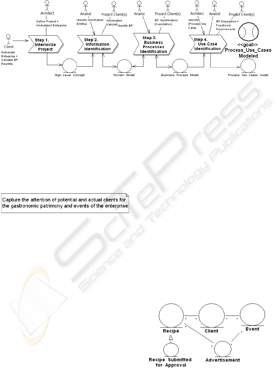
Our contribution is illustrated (Figure 1) using an
adapted notation of the Business Process Model
(Hans-Erik Eriksson, 2001). The process behind
PUC is now introduced, and the used notation is
completely explained throughout Section 3.3 –
Business Process Identification. Three actors are
defined: architect, analyst and client. The first two
belong to the software development team, and the
client is a member of the client enterprise to whom
was given the responsibility of dealing with the
activities of BPM and/or SE. The models produced
are outputs of each step and are represented by
entities
that are inputs for the next BP or the goal
itself. PUCs’ Step 2 (Information Identification) and
Step 3 can be iterative, since, it is possible that Step
2 entities identify new BPs, and that these BPs (Step
3) identify new entities (if they are defined within
the scope of the project).
Different abstractions provided by different
techniques are used to represent the information
acquired. These techniques are: UML (OMG, 2003)
that besides the notation, provides class diagram and
activity diagram to produce the domain model and
process use cases model respectively; Wisdom
(Nunes, 2001) which provides two of the main
concepts behind PUC: (i) “process interiorization”
(Kreitzberg, 1999) and (ii) “requirements discovery”
defined within its Requirements Workflow; the
Business Process Model (Hans-Erik Eriksson, 2001)
which provides the (adapted) notation used in
Process Use Cases for modeling BPs and Usage-
Centered Design (Constantine, 2006) which
provides the concepts of (essential) use case and
actor.
3 ILLUSTRATING PROCESS USE
CASES
In order to illustrate Process Use Cases (PUC), a
project under development for a small enterprise is
presented. This (non-profitable) enterprise, related to
a local governmental library (in Madeira, Portugal),
is responsible for the bibliographic investigation on
gastronomy. The idea of the director is to divulgate
the gastronomic events promoted by the enterprise
and the existing gastronomic recipes in a website.
After a first approach where an attempt was made to
understand the main activities of the enterprise, it
was possible to know which were the enterprises’
main products: the identification and cataloging of
gastronomic recipes and the organization of
gastronomic events. After this, the 4 Steps of PUC
where applied in order to identify the functional
requirements for the project that are presented in the
sequel.
3.1 Step 1 – Interiorise Project
This is the only unstructured part of PUC. The High-
Level Concept (HLC) is a paragraph (technology
independent) that describes the part of the system (or
full system) that is going to be implemented. The
High-Level Concept must be understood by all the
stakeholders (the community) of the project
promoting a shared vision that will help the project
community to keep focused on the product
development.
In this step client and architect agree on a High-
Level Concept for the project. To do this, it is
important to understand the scope of the project
within the enterprise global activity, so, it is
ICEIS 2007 - International Conference on Enterprise Information Systems
302
necessary to understand how the enterprises’
activities lead to the production of its main
product(s), and, what is the strategic reason that
leads to the need of automation. Artifacts such as
enterprise hierarchical organizational structure and
legislation may be important, and, by interviewing
the clients’ project manager, member preferably
related to the enterprises’ process of decision,
sufficient information may already be compiled to
produce the High-Level Concept.
In the project presented in this document the High-
Level Concept agreed is presented in Figure 2.
Figure 1: Step 1- High-Level Concept for the project.
3.2 Step 2 - Information Identification
Information is very stable within an enterprise.
Mainly, information manipulated by core business
processes is persistent from the birth of the
enterprise until its closure and is independent from
the technology used to manipulate it. Information
parts relate to each other naturally, and the objective
is to produce a model, the domain model, that
contains and relates all the identified parts.
In this step, the analyst identifies the main
concepts of information defined in the High-Level
Concept. These information concepts are
represented with entities that, will be the first ones in
the domain model. An entity is defined in Wisdom
(Nunes, 2001) as a “class used to model perdurable
information (often persistent)”. It is also
complemented that, “entity classes structure domain
(or business) classes and associate behavior, often,
representing a logical data structure”. These entities
represent information (not actions, actors, nor
business processes; eventually name may coincide)
and relate to each other composing a meaningful
structure. This structure has relations of hierarchy
(inheritance), dependency (composition) and
possession (association) and is modeled using a
class diagram (OMG, 2003).
In PUC, the entity stereotype is used instead of
the class stereotype because at this stage it is a more
accurate concept of information. Since this model is
described using a standard language (UML) it can be
used along all the software development process,
including implementation-time when it can be used
to generate database tables and (programmed)
classes to manipulate these entities. The domain
model must be updated at any stage in the process
when new entities are revealed (especially as a result
of Step 3). It is suggested that the analyst describes
the class diagram in natural language to the client to
achieve diagram validation.
In the project presented in this document, the
first entities taken from the High-Level Concept
were: “client”; “recipe” and “event”. The entity
“client” existence, although implicitly related to the
events, was reinforced when it was noticed that the
business process for recipe capture also involved
donation of recipes by “clients”. The first entities
identified were then combined with other entities
identified in Step 3 (Business Processes
Identification) to compose a single information
structure as shown in Figure 3.
Figure 3: Step 2 - Domain Model for the project.
Figure 2: Process Use Cases.
PROCESS USE CASES: USE CASES IDENTIFICATION
303
3.3 Step 3 - Business Processes
Identification
Business processes (BP) exist in an enterprise to
achieve a certain objective, a goal, a product, that
can be described by information (associated with
this product). BPs happen as many times as the need
to give response to the needs of some enterprise
member or third party (e.g. client) with some
responsibility (active or passive, with some relation
to the enterprise) within the activity of the
enterprise. Many enterprise members can interact
with these processes by carrying out some complete,
unitary task, in which many different entities can be
manipulated (consumed or produced). In order to be
able to control (e.g. reorganize) these BPs its
important to an enterprise to maintain complete and
detailed information of relations among BPs, their
inputs, outputs, actors and triggering events.
In this step, analyst and client will identify, relate
and detail business processes. The identification of
BPs should take place, at least, from the business
unit (in an hierarchical perspective) “directly”
responsible for the information being managed, i.e.
unit(s) that consume or produce this information to
achieve complete and meaningful tasks. Business
processes that relate “directly” to the information
identified until this stage must be documented in
order to understand all the manipulation made over
the identified information, if within the scope of the
project defined in the High-Level Concept.
BPs are named according to their goal (the
product of the BP), whether it is a service,
information or a material product (e.g. product
“television”, BP name “build TV”). BPs can be
divided into (sub
-)business processes (that are
represented with the same notation) in an vertical
hierarchy. BPs products are represented by entities,
the associated information.
The persons that interact with the business
process are called actors (Constantine, 2006) which,
as defined in Usage-centered design, is “a user that
interacts with a system”. In process use cases,
business processes are the “system”, and the
stereotype used is the UMLs’ “user”. Actors are
associated to BPs using association and their
objective(s) are written in natural language (e.g.
“approve recipe”) separated by a plus signal (+)
naming the association. When an actor triggers the
business process, an event is generated and its
relation with the business process is represented
with a flow (arrow form), and, his objective is to
obtain the product(s) achieved by that BP (the
output(s)).
The outputs and inputs (information, resource
and output in the Business Process Model (Hans-
Erik Eriksson, 2001)) are represented by entities.
Business processes can be related among each other,
i.e., the conclusion of the business process (which is
an event) serves as a trigger to the next providing an
information entity shared by the two BPs in a
horizontal hierarchy. When the flow is towards the
business process it is an input (and generates an
event) and the contrary direction represents an
output. Associations can be bi-directional
representing event, input and output in both
directions.
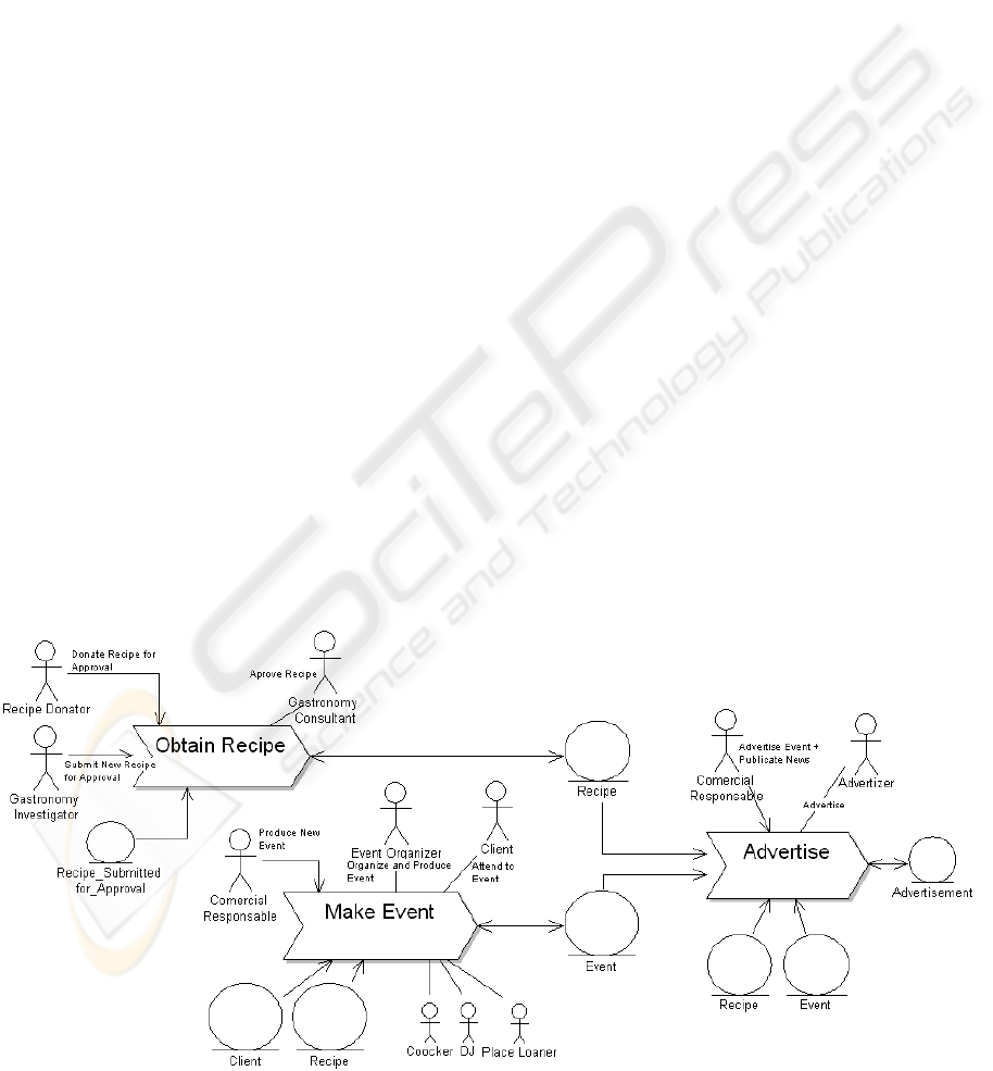
In the project presented in this document, 3
business processes that directly manipulated the
entities “client”, “recipe” and “event” (Step 2) where
identified (Figure 4): (i) “Obtain Recipes”, to
Figure 4: Step 3 – The Business Process Model for the project.
ICEIS 2007 - International Conference on Enterprise Information Systems
304
provide the necessary information about recipes (by
cataloging); (ii) “Make Event”, to provide the
information about events dates and more detailed
information and (iii) “Advertise”, which was
modified, in order to introduce the needed activities
to support the information for the website. After this,
the client validation diagram and the domain model
was updated.
3.4 Step 4 - Use Cases Identification
The documentation of business processes in a
language that every intervenient (stakeholders)
understands is important to enable correct dialogue
over the actors, activities (tasks) and goals. BPs can
be partially or completely automated or not
automated at all.
In this step, analyst and client model the tasks
(activities) of the business process which performed
by actors along the BP until achieving the targeted
goal. “A task (task case, as defined in Usage-
centered design (Constantine, 2006)) represents a
single, discrete user intention in interaction with a
system that is complete and meaningful”, for
instance it is an essential use case which is defined
by the same author as “a specially structured form of
a use case, one that is expressed in so-called
essential form, that is, abstract, simplified, and
independent of assumptions about technology or
implementation”.
The BP identified in the previous step (Step 3) is
designed with the process use cases model, through
the use of an UMLs’ activity diagram (OMG, 2003)
using swimlanes. Tasks carried out by an Actor are
placed in the same swimlane. The activity diagram
begins with an “initial” stereotype and ends with a
“final” stereotype. The transition relation is used
between tasks. UMLs’ activity stereotype is used to
represent tasks of the BP which are not automated
and the use case stereotype is used for the automated
tasks. Fork and decision are used to represent
parallel activities and decision points.
Once all activities are identified it is important
that the architect (with the client) decides which
tasks should be automated. When this happens, a use
case (stereotype change) takes the place of that
activity.
In the project presented in this document, based
on the analysis of the models produced until the
previous step (Step 3), with cooperation of the
client, it was noticed that the BPs that could mostly
contribute to the website were “Obtain Recipes” and
“Advertise”. In another perspective, “Obtain
Recipes” could provide more valuable information
for the website than “Make Event”, and by means of
the generalization of the tasks of “Advertise”
support could also be achieved to advertise “news”
about “recipes” and “events”.
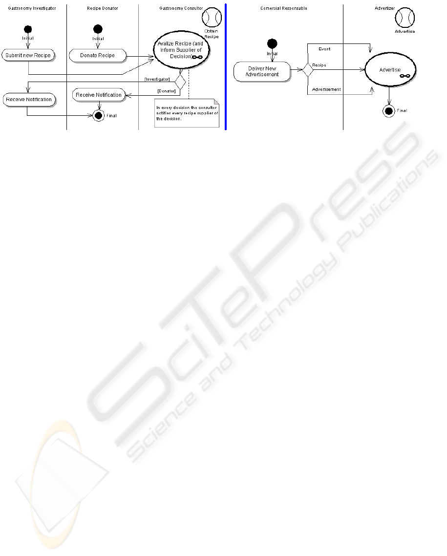
Two activities where transformed into use cases
to produce the information wanted for the website,
i.e. “recipes” and “news” (see Figure 5). The task
“advertise” was generalized in order to support
every action of advertising for both “recipes” and
“news” that could also support the advertising of
“events”, inducing simplification and completeness
of the task.
This was already sufficient information to
produce a financial proposal for the development of
the project and to start the SE analysis phase.
This is the model (Process use cases model)
where users and interactive information system
meet. However, it is not the purpose of PUC to
establish the relation between use cases and entities.
This is a task left for a software engineering process
which carries along the information generated until
this stage and brings consistency to this relation in
later stages of that process.
Figure 5: Step 4 - Process Use Cases model for “Obtain Recipe” and “Advertise”.
PROCESS USE CASES: USE CASES IDENTIFICATION
305
4 INTEGRATING PROCESS USE
CASES
Process Use Cases (PUC) is part of Goals, an agile
software construction process that guides a software
team to the definition, construction and maintenance
of an interactive information system for an
enterprise.
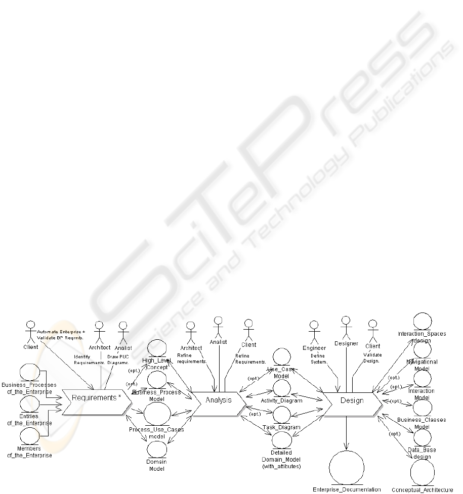
According to Goals, which business process is
illustrated in Figure 6, after the definition of the
requirements, another process (phase) is applied for
analysis and design of the software to be developed
(or modified). For this reason, it is also an objective
of this document to explain how PUC should be
integrated with software analysis and design
methodologies in order to achieve correct software
definition, the objective behind the Goals process.
Most software engineering methodologies gather
both analysis and design phases, however, it is
important to understand that these phases are
different since in analysis the objective is to
complete the understanding of the problem, and in
design the objective is to conceive the solution that
will solve that problem, resulting in the complete
definition of the interactive information system to be
built.
Although all information generated along the
process should be available to all the phases, Goals
suggests sharing a minimal set of crucial information
(modeled using the same notation) for correct
system definition. Because Goals is still under
development, integration is presented only for the
first 3 phases:
• between requirements (identification) and
analysis: High-Level Concept (optional); Business
Process Model (optional); Process Use Cases
model; Domain Model.
• between analysis and design: Use Case Model
(opt.); Activity_Diagram; Task Diagram (opt.);
Detailed Domain Model (detailed with class
attributes).
• the outputs of the design phase are: Conceptual
Architecture (opt.); Interaction Spaces design;
Navigational Model; Interaction Model (opt.);
Business Classes Model (opt.); Database design.
The chosen analysis methodology should be: (i)
object-oriented and use case-driven, and; (ii,
optional) architecture-centric in order to achieve
consistency validation in system definition, i.e., to
combine in one view usage, interaction interfaces,
system behavior and information entities and the
relations among.
The choice for the design methodology should
depend on: (i) the compatibility with the objects
generated in the analysis phase; (ii) the non-
functional requirements revealed in the analysis
phase and the (iii) available resources, i.e., modeling
detail needed for the development of the interactive
system in: user interface usability, system behavior
refinement and database integrity; the human
resources available for the modeling, time and
budget constraints.
PUC can be considered highly compatible with
Wisdom (Nunes, 2001), Goals Multimedia (Pedro
Valente, 2007) and Usage-centered design
(Constantine, 2006). All these methodologies can
also be applied for the design phase. PUC can also
be compliant with methodologies such as: (i)
Extreme Programming (XP) (Beck, 1999)
connecting use cases with the “user stories” and the
domain model with the “architectural spike”
predicted in XP, and, with (ii) the Rational Unified
Process (RUP) (Kruchten, 1999) which provides an
Figure 6: Goals Software Construction Process (partial view).
ICEIS 2007 - International Conference on Enterprise Information Systems
306

extensive set of models to complete the phases of
analysis and design. As an extra requirement, the
compatibility of the definitions of: essential use case
(use case)(Constantine, 2006), entity (set of
information) (Nunes, 2001) and actor
(user)(Constantine, 2006) should be observed.
5 CONCLUSIONS
Process Use Cases (PUC) is a methodology that
identifies use cases as a leap for software
construction producing valid artifacts for both
activities of Business Process Management and
Software Engineering. PUC has been already
applied in over 10 different real software
development projects for the Information and
Computing Centre in University of Madeira (UMa),
Portugal, for the automation of at least one business
process per project. It was applied by both
undergraduate students and IT professionals and
shared with UMa managers for both Business
Process Management and Software Engineering
activities always resulting in a firm artefact that
promoted consensus between the stakeholders.
In a modeling perspective, achieving the most
appropriate level of abstraction to name use cases
can be a very difficult task in software engineering if
no global comprehension exists of the scope of the
project within the enterprise organization. Using
PUC is easier to reach the appropriate abstraction to
nominate the (essential) use cases in a way that they
make sense in both Business Process Management
and Software Engineering disciplines. This is
possible through the definition of compatible
formalizations of the stereotypes used (entities,
users, business processes, activities and use cases),
that are provided by LUCID (Cognetics Corporation,
1999), Wisdom (Nunes, 2001) and Usage-centered
design (Constantine, 2006), producing a notation
also suitable for the application of agile software
analysis and design methods.
Future work is still to be made in the full definition
of the Goals software construction process (and
integration with existing methodologies) for
requirements identification, analysis, design,
development, test, installation and maintenance.
System size, complexity and general software
quality attributes estimation can be important
functionalities that determine the production of the
correct interactive information system.
REFERENCES
Beck, K. (1999). Extreme Programming Explained:
Embrace Change. Addison-Wesley. ISBN:
0201616416.
BPMI. (May 3, 2004). Business Process Modeling
Notation (BPMN) - Version 1.0. Retrieved from
March 5, 2007,
http://www.bpmn.org/Documents/OMG%20Final%20
Adopted%20BPMN%201-0%20Spec%2006-02-
01.pdf
Constantine, L. (2006). Activity Modeling: Toward a
Pragmatic Integration of Activity Theory with Usage-
Centered Design. Retrieved March 5, 2007 from
http://www.foruse.com/articles/activitymodeling.pdf
Eriksson, H.-E., Pencker, M. (2001). Business Modeling
With UML: Business Patterns at Work (1st edition
ed.): John Wiley & Sons. ISBN: 0471295515.
Jacobson, I., Ericsson, M., Jacobson, A. (1994). The
Object Advantage: Business Process Reengineering
with Object Oriented Technology. : Addison-Wesley
Professional; 1st edition. ISBN: 0201422891.
Koehler, J., Tirenni, G., Kumaran, S. (2002). From
Business Process Model to Consistent
Implementation: A Case for Formal Verification
Methods. In Proceedings of EDOC 2002 - 6th
International Enterprise Distributed Object Computing
Conference.
Kreitzberg C. (January, 1999). The LUCID Framework
(Logical User Centered Interaction Design) (Pre-
Release Version 0.4). Retrieved March 5, 2007, from
http://ei.cs.vt.edu/~cs3724/notes/lucid-0.pdf
Kruchten, P. B. (1999). The Rational Unified Process (An
Introduction). Addison-Wesley Professional; 2 edition
(March 14, 2000). ISBN: 978-0201707106
Nunes, N. (2000). Object Modeling for User-Centered
Development and User Interface Design: The Wisdom
Approach. PhD. Thesis, University of Madeira (UMa),
Funchal, Madeira.
OMG (2003). Unified Modeling Language Specification
(Version 1.5). Retrieved March 5, 2007, from
http://www.omg.org/docs/formal/03-03-04.pdf
ISO (1999). ISO 13407:1999. Human-centered design
processes for interactive systems. First edition.
Retrieved March 5, 2007, from
http://www.iso.org/iso/en/CatalogueDetailPage.Catalo
gueDetail?CSNUMBER=21197
Valente, P., Sampaio P. (2007). Goals: Interactive
Multimedia Documents Modeling. Lecture Notes in
Computer Science 4385, Tamodia 2006. ISBN: 978-
3540708155. pp. 169-185.
Remco M. Dijkman, S. M. M. J. (2002). Deriving Use
Case Diagrams from Business Process Models.
Retrieved March 5, 2007, from
http://doc.utwente.nl/fid/1209
PROCESS USE CASES: USE CASES IDENTIFICATION
307
