
CHECKING BEHAVIOURAL CONSISTENCY OF UML-RT MODELS
THROUGH TRACE-BASED SEMANTICS
Luis E. Mendoza Morales
Departamento de Procesos y Sistemas, Edificio de Matem
´
aticas y Sistemas, Universidad Sim
´
on Bol
´
ıvar
Apartado 89000, Baruta, Caracas, 1080-A, Venezuela
Manuel I. Capel Tu
˜
n
´
on, Kawtar Benghazi Akhlaki
Departamento de Lenguajes y Sistemas Inform
´
aticos, ETSI Inform
´
atica
Campus Aynadamar, Universidad de Granada, 18071 Granada, Spain
Keywords:
Real-time software systems, UML-RT, Formal semantic, Formal specification, CSP+T.
Abstract:
Starting from a methodological approach intended to obtain a correct system specification in CSP+T from a
UML–RT model of an RTS, we develop now a systematic procedure to check whether the obtained design
is consistent with other views of the same system, such as the ones given by class, composite structure and
state machines diagrams. To achieve this objective, a formal semantics of the notational elements of UML–RT
according to CSP+T process terms is presented, which guarantees that system requirements are preserved from
their initial UML–RT modelling to the final system implementation. As a consequence, the formal support
given by the compositional refinement of CSP+T process terms will allow performing the system’s software
compositional verification. In addition, the derived formal semantic definitions are applied to the Production
Cell case study.
1 INTRODUCTION
The increase of the technological level of software de-
velopment capabilities and the presence of computer
systems everywhere has encouraged the deployment
of real–time systems (RTS) to monitor and control
many different kind of applications, which range from
household appliances to control of chemical plants,
nuclear power stations, command and control systems
or the control of laboratory experiments. The com-
plexity of modern real–time embedded control sys-
tems (RTECS) together with the absence of appropri-
ate software tools is one of the reasons for the large
number of errors in the design and implementation
of these systems. Moreover, exhaustive testing is im-
possible, because of the combinatorial explosion of
different runs that an RTECS can undergo when it ex-
ecutes.
Formal methods are the conceptual tools that al-
low the construction of reliable RTECS despite of
their complexity. It has been pointed out by sev-
eral authors (Evans et al., 1998; Kim and Carring-
ton, 1999) that advancing towards the combination
of semi–formal modelling languages, such as UML,
thereby contributing to a more widespread use of rig-
orous Software Engineering methods in the develop-
ment of these systems.
This article describes how to give a timed seman-
tics to the UML–RT notational elements in terms of
the CSP+T formal specification language (
ˇ
Zic, 1994),
and establishes the consistency conditions of the mod-
els obtained by applying a transformational method-
ology (Benghazi et al., 2007).
Other contributions based on the formalization of
the dynamic model describing the behaviour of dif-
ferent types of systems have been carried out in the
OMT’s dynamic model (Cheng and Wang, 2002),
UML’s state machine (SM) (Engels et al., 2001a)
and sequence diagrams (Haugen et al., 2005). The
first one formalizes (SMDs) by giving them a struc-
tured semantics based on LOTOS (Bolognesi and
Brinksma, 1987). In the second one a formal trace
semantics is given to SMs in the context of composite
structure diagrams of UML 2.0 (OMG, 2004); thus, a
semantic interpretation as CSP process terms is given
to capsule–SMs, connectors and ports (Engels et al.,
205
E. Mendoza Morales L., I. Capel Tuñón M. and Benghazi Akhlaki K. (2007).
CHECKING BEHAVIOURAL CONSISTENCY OF UML-RT MODELS THROUGH TRACE-BASED SEMANTICS.
In Proceedings of the Ninth International Conference on Enterprise Information Systems - ISAS, pages 205-211
DOI: 10.5220/0002395102050211
Copyright
c
SciTePress

2001b). The third one describes STAIRS, an approach
to the compositional development of UML’s sequence
diagrams resorting to a three-event trace semantics.
The above proposals lack of an integrated view of di-
agrams or, more accurately, UML submodels of the
system under development as our own proposal does
(Benghazi et al., 2007).
To demonstrate the consistency between UML-RT
submodels we define a partial semantic mapping into
a common semantic domain given by CSP+T trace
semantics. In this work we give a semantic founda-
tion of the UML–RT composite diagrams elements
and the consistency conditions required to assure that
the obtained system specification fulfills the time con-
straints modeled in UML–RT. Our final challenge is
to demonstrate the semantic consistency of a UML–
RT model and its corresponding CSP+T specification.
The paper is organized as follows. In the next sec-
tion we give a brief description of our method. Sec-
tion 3 shows a overview on UML–RT and CSP+T, as
specification languages supporting our approach. In
section 4, we describe the mapping between UML–
RT entities and CSP+T semantic domain to establish
the semantic basis of the method. In section 5, we
establish the consistency conditions to check the be-
havioural consistency of the models. In section 6, we
apply the products of this work to the Production Cell
case study. The last section gives a conclusion and
discusses future work.
2 TRANSFORMATIONAL
METHODOLOGY
We can perform the specification of the structural and
behavioral aspects of RTS methodologically (Beng-
hazi et al., 2007). These two different viewpoints
of a system are usually attained in UML–RT by
using Class and Structure diagrams, and by using
SMDs, respectively. We apply a transformational
method, based on a proposed set of transformation
rules (Benghazi et al., 2006), which allow us to create
a CSP+T model from a UML–RT analysis model of a
given RTS. As it can be seen in Figure 1, the process
is divided into two main phases: the first one (top–
down modelling process) to model the system using
UML–RT, while the second one (bottom-up specifica-
tion process) obtains the formal specification in terms
of CSP+T by the transformation of each UML–RT
submodel.
As Figure 1 shows, mapping links are continu-
ously established between the UML–RT diagrams of
components in which the system is structured and
their formal specifications in terms of CSP+T pro-
cesses. These links demonstrate how CSP+T syntac-
tical terms are used to represent the real–time con-
straints and the internal components and connectors
that constitute the system architecture, at different
levels of description detail.
In the semantic domain, lower level pro-
cesses refine these of the upper levels in the
system design. For instance, let us con-
sider P
i:2...n
= {[[State machine diagrams(i)]]},
P
1
= {[[Composite structure diagrams]]}, P
0
= {[[Class
diagrams]]}, where P
0
, P
1
, P
i
are structured process
terms of CSP+T representing different view-
points of UML–RT diagrams of a system. The
following refinement relation between processes,
P
0
⊑ P
1
⊑ k
i:2...n
P
i
holds.
Process specifications may be constructed from
the specifications of their components, in a way that
reflects the trace semantics of CSP operators. By the
application of parallel composition and hiding opera-
tors are obtained the more abstract processes within
the specification phase of the system development.
In (Schneider, 2000) are explained a series of rules
demonstrating that the verification of the entire tar-
get system can be obtained from the composition of
subsystems correction proofs, which is a result of the
fact that the satisfaction relation is closed w.r.t. the
conjunction operator,
If P
i
|= S
i
⇒ System ≡ (k
i:1...n
P
i
) |= (
i:1...n
S
i
) ;
thus, this result allows us to carry out the analysis of
complex systems by compositional refinement.
3 THE SPECIFICATION
LANGUAGE
CSP+T (
ˇ
Zic, 1994) is a new real–time specification
language which extends CSP (Communicating Se-
quential Processes) (Hoare, 1985) by introducing a
new set of constructs to allow the description of com-
plex event timings from within a single sequential
process, thereby providing a valuable insight into the
behavioural specification of RTS.
A CSP+T process term is defined as a tuple
(αP,
P ), where αP = Comm act(P) ∪ Interface(P)
and αP is named the communication alphabet of
P .
These communications represent the events that pro-
cess P receives from its environment (made up of all
the other processes in the system) or those that occur
internally, such as the event τ which is not externally
visible.
The CSP+T language is defined by the following
grammatical rules. Given a set
E of events, a set M
of marker variables, a set I of time intervals, and a set
ICEIS 2007 - International Conference on Enterprise Information Systems
206
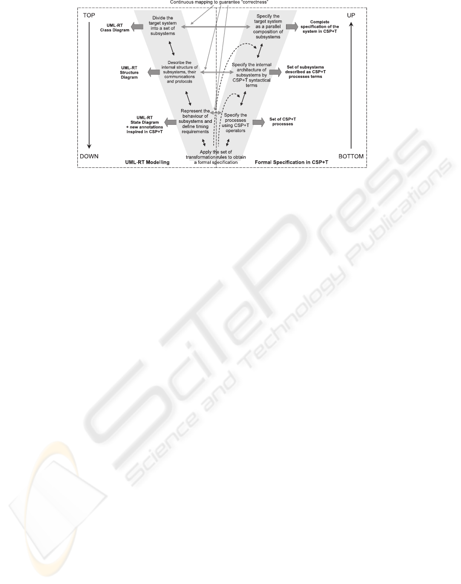
Figure 1: Methodological approach to derive a correct and complete formal specification of RTS (Benghazi et al., 2007).
of process names
P , the syntax of CSP+T is given by
P ::= Stop | Skip | e 1 v → P | P; Q | P2Q |
P⊓ Q | P\ A | P |[A]| Q | P ||| Q |
I(t,T).a → P | I(t, T) → P
where e ∈
E , A ⊆ E , v ⊆ M , I ⊆ I , P ⊆ P . The in-
terpretation of some operators is as it follows. The
processes Stop and Skip represent, respectively, dead-
lock and termination. The prefix processes e 1 v → P
annotates that the process first engages in the event
e, then stores in the marker variable v the event oc-
currence of e, and then becomes the process term
P. The processes P ⊓ Q and P2Q represent inter-
nal and external choice between P and Q, respec-
tively. That means, while P ⊓ Q performs an inter-
nal (τ–)action when evolving into P or into Q; on
the other hand, P2Q requires the occurrence of an
observable action of either P or Q. For example,
(a 1 v
a
→ P) ⊓ (b 1 v
b
→ Q) internally chooses to
become either a 1 v
a
→ P or b 1 v
b
→ Q. Instead,
(a 1 v
a
→ P)2(b 1 v
b
→ Q) offers the communica-
tion events to its environment a 1 v
a
or b 1 v
b
and
evolves into P or Q, respectively, depending of an ex-
ternal choice. This distinction shall be relevant for the
translation of SMDs that is performed in this work.
The process P\ A behaves like P except that all oc-
currences of set of events A are hidden. Finally, the
parallel composition P |[A]| Q results in a interleav-
ing of P and Q, which is denoted as the process term
P ||| Q, except for the events in A on which P and Q
must synchronize.
CSP+T is a superset of CSP, as a major change
to the latter, the traces events are now pairs denoted
t.e, where t is the global absolute time at which event
e is observed. The operators related with timing
and enabling–intervals included in CSP+T are (
ˇ
Zic,
1994):
• The special process instantiation event denoted ⋆
(star). This event is unique in that it must be as-
sociated with a unique, global time, at which the
system of processes may start.
• The time capture operator (1) is associated to
time stamp function a = s(e) that allows storing
in a variable a the occurrence time of an event e
when it occurs.
• The event–enabling interval can be seen from two
viewpoints. When we write I(t
1
,T).a → P the
process P can only engage in the event a if it oc-
curs within the time interval (t
0
+ t
1
,t
0
+ t
1
+ T).
But when we write I(t
1
,T) → P the process P is
executed in the instant after the “expiration” of the
time interval (t
0
+t
1
,t
0
+t
1
+T), since there is no
event to engage to within this interval.
4 UML–RT ENTITIES AND CSP+T
As UML establishes, the behavior of UML–RT struc-
tural elements (capsules and protocols) are specified
among other UML diagrams by SMDs) A UML–
SMD represents a hierarchical automaton that in-
cludes initial states, final states, choice states, sim-
ple states, composite states and transitions between
states (OMG, 2004). The syntax for a transition
label has three parts, all of which are optional:
Event[Guard]/Action. A guard is a logical condition
and a guarded transition may only occur if the guard
is true.
The graphical representation of a CSP+T pro-
cess term correspond to the simplest form of SM,
hence we can map transitions of SMs to events of
CSP+T and states of SMs to processes of CSP+T.
CHECKING BEHAVIOURAL CONSISTENCY OF UML-RT MODELS THROUGH TRACE-BASED SEMANTICS
207

The one–to–one correspondence between states and
process definitions facilitates our formal reasoning
about the dynamic behaviour of processes. However,
it is not enough to capture the behaviour of a SM
associated to a capsule precisely. As established
by UML–RT, each capsule operates according to a
SM with a clear interface, which responds to events
and generates actions through ports. To differentiate
between external events and operations, we define
roles that a port can perform. A signal arriving
to a capsule port from the environment is usually
interpreted as a event by a capsule SM; on the other
hand, the signals exiting from a capsule are the result
of executing the operations. The following definition
allows specifying UML–RT capsule SMs in terms of
CSP+T processes.
Definition 1 (Capsule SM). A capsule SM is repre-
sented in terms of CSP+T processes as a tuple SM =
(S,E ,B ,M , I , O , P ,Port), where:
• S is a finite set of processes
• E is a finite set of events
• B is a set of boolean expressions (guards)
• M is a set of marker variables
• I is a set of event–enabling intervals
• O is a set of operations
• Port is a finite set of port names
• A process relation P ⊆ S ×E × B × M ×I × O ×Port,
where (s,e,b, a,I,c,p) ∈ P, is denoted by
P = {b}I(T,t
1
).trigger(e) 1 a → (effect(c) → P
′
)
2
I(t
1
+ T) → Timeout
where:
– a = s(e) corresponds to the time stamp of occurrence
of the event e
– T is the max time, started from the time t
1
, in which
the process P wait for event e
– I(t
1
+ T) represent an instant of time.
– port : E + O → Port + {Int} is a function that as-
sociates to each event or operation x a port name in
Port according to a distinguished label Int which des-
ignates the type of event or effect, where:
∗ for all e ∈ E , if port(e) = Int then trigger(e) = e
else trigger(e) = port(e)
in
?e.
∗ for all c ∈ O , if port(c) = Int then effect(c) = c
else effect(c) = port(c)
out
!c.
The above definition is semantically coherent
with the one given by UML–RT w.r.t. the required
behaviour associated to the capsule, that is specified
according to CSP+T semantics. The capsule reacts
to the received signals through its ports and sends
signals through other ports too. Therefore, the def-
inition 2 is completed by definition 3 that is actually
a CSP+T extension of the CSP one in (Engels et al.,
2001b).
Definition 2 (Process view). Let SM =
(S ,E ,B ,M , I , O ,P,port) be a capsule SM, let
CSP + T(SM) be the process associated to SM, and
p ∈ Port. Define
E
′
= {I.p
′
in
?e | p
′
6= p} ∪ E
Int
and
O
′
= {p
′
out
!c | p
′
6= p} ∪ O
Int
.
Then, the process view with respect to the port p is defined
as V
p
(CSP+ T(SM)) = CSP+ T(SM) \ (E
′
∪ O
′
)
This definition uses the hiding (\) operator, de-
fined in section 3. The process CSP+ T(SM) \ (
E
′
∪
O
′
) behaves like the process CSP+T(SM) except that
all occurrences of the events in
E
′
∪
O
′
are hidden.
All these events are removed from the interface of
the process, since no other process are required to en-
gage in them, and thus the events become internal to
the process CSP + T(SM). The process view speci-
fies the events that occur in the capsule SM which are
of interest for a particular interaction or which are re-
ceived/sent from/to a particular port. In the definition
2, V
p
(CSP+ T(SM)) represents the view of the cap-
sule state machine CSP+ T(SM) from other capsule
SM connected to it through the port p.
The behavioural organisation of the structural el-
ements of UML–RT (mainly capsules) is specified
through Composite Structure Diagrams. The most
important aspect of this UML–RT diagram is that
reflects the compositional and concurrent aspects
of processes, which characterizes the dynamic be-
haviour of any system and becomes of paramount im-
portance for RTS. This composition is made of con-
nectors and ports, but UML–RT does not set anything
about the behaviour of connectors.
UML–RT settles down that every capsule SM is
associated to an event queue where input messages
are stored. Connectors are responsible for carrying
out the task of storing and ordering the events. We
define a extension of the uni–directional connector
with capacity n and non–blocking behaviour with
time constraints specification, as it follows:
Definition 3 (Connector). A connector is C =
(N,In,Out,M ,I) where:
• N is the capacity of the buffer
• In is the input channel
• Out is the output channel
• M is a set of marker variables
• I is a set of enabling intervals
• A buffer relation B ⊆ N × In × Out × M × I , where
ICEIS 2007 - International Conference on Enterprise Information Systems
208

(n,in,out,a, I) ∈ B, is denoted by
let B(hi) = (I
i
.in?x 1 a
i
→ B(hi)
2I
i
→ Timeout)
B(s) = (I
o
.out!head(s) 1 a
o
→ B(tail(s))
2I
o
→ Timeout)
2(#s ≥ n&I
i
.in?x 1 a
i
→ B(s)
⊓#s < n&I
i
.in?x 1 a
i
→ B(s
⌢
hxi))
within B(hi)
where:
– a = s(x) corresponds to the time at which a message
contained in x is received/sent
– I
i
and I
o
represents the input enabling interval and
the output enabling interval, respectively.
The parallel composition in CSP+T is a mech-
anism that puts two processes together to evolve
concurrently. The interactions that occur between
component processes over time (or “communi-
cations”) may be regarded as events that require
simultaneous participation of both processes. In
UML–RT two capsules executing concurrently can
be described by the CSP+T operator |[ ]| and a
connector. This construct is called in (Engels et al.,
2001b) “capsule–connector–capsule”.
Definition 4 (Capsules composition). Let A and B be two
capsules connected by two ports p1 and p2 through a con-
nector associated to a previously defined connector process
C, and let the capsule SMs associated to A and B be SM
A
and SM
B
, respectively. Then the semantics of this construct
is defined by the following CSP+T syntactical term
V
p1
(CSP+ T(SM
A
)) |[p1
in
,p1
out
]| C
|[p2
in
,p2
out
]| V
p2
(CSP+ T(SM
B
))
We denote this process as CSP+ T
p1,p2
(SM
A
,C,SM
B
)
Capsules connected through ports that intercom-
municate according to previously defined protocols.
In CSP+T, the protocol refers to the alphabet of
communication events. The Definition 2 is a view of
a capsule SM that focuses on sending and receiving
messages through a particular port (Engels et al.,
2001b). The alphabet of communication can be
obtained by defining a relationship between the
process views of capsules that communicate through
a connector.
Definition 5 (Communication alphabet). Let CSP +
T
p1,p2
(SM
A
,C,SM
B
) be the capsule composition of two
capsules A and B, connected by two ports p1 and p2 through
the given connector process C, and let V
p1
(CSP+ T(SM
A
))
and V
p2
(CSP+ T(SM
B
)) be the process views associated to
SM
A
and SM
B
, respectively. Then the communication al-
phabet with respect to the connector C is defined as
α
C
(CSP+ T
p1,p2
(SM
A
,C,SM
B
)) =
V
p1
(CSP+ T(SM
A
)) ∩ V
p2
(CSP+ T(SM
B
))
This definition allows to refine the behavioural re-
lationship among capsules that must be respected as a
contract established by the protocol implemented by
the connector.
5 BEHAVIOURAL CONSISTENCY
We need to ensure the consistency from the com-
munication and interaction viewpoint of diagrams
in order to validate the UML-RT models of the
target system. In this sense, we realize that the
following two consistency problems may occur: (a)
consistency between two capsule SMs, and (b) the
consistency problem between two capsule SMs and
a protocol SM. According to (Engels et al., 2003),
the consistency problem (a) occurs because the inter-
action of two capsule SMs could lead to deadlock.
Furthermore, two capsule SMs interaction must be
conform to the protocol specified in the protocol SM
in order to avoid the consistency problem (b). The
following consistency conditions are necessary to
assure the horizontal and vertical consistency (Engels
et al., 2001b) according to CSP+T semantics.
Condition 1 (Deadlock freeness). Two SMs SM
A
and
SM
B
associated to capsules A and B, and communicated by
a connector with behaviour C through the ports p1 and p2,
are consistent if the induced system of CSP + T processes
CSP+ T
p1,p2
(SM
A
,C,SM
B
) is deadlock free.
Condition 2 (Protocol consistency). Two capsules A and
B connected by a connector with behaviour C through the
ports p1 and p2 are consistent with a protocol Prot iff CSP+
T
p1,p2
(SM
A
,C,SM
B
) ⊑
τ
Prot.
6 CASE STUDY
6.1 The Production Cell UML–RT
The Production Cell is a standard example for evalu-
ating methodologies for designing embedded systems
(Lilius and Porres, 1999). The model includes several
machines that must be coordinated in order to forge
metal blanks. We decided to model one of the central
element of system: the Press. The task of the Press is
to forge metal blanks. Figure 2 shows its architecture.
The Press is composed of two basic components,
the Plant and the press controller (PC). These ele-
ments are represented by two subcapsules Plant and
PC shown in Fig. 3.
The subcapsule PC has two ports: the port Pp2
to communicate with the Press and the port Ppc to
CHECKING BEHAVIOURAL CONSISTENCY OF UML-RT MODELS THROUGH TRACE-BASED SEMANTICS
209
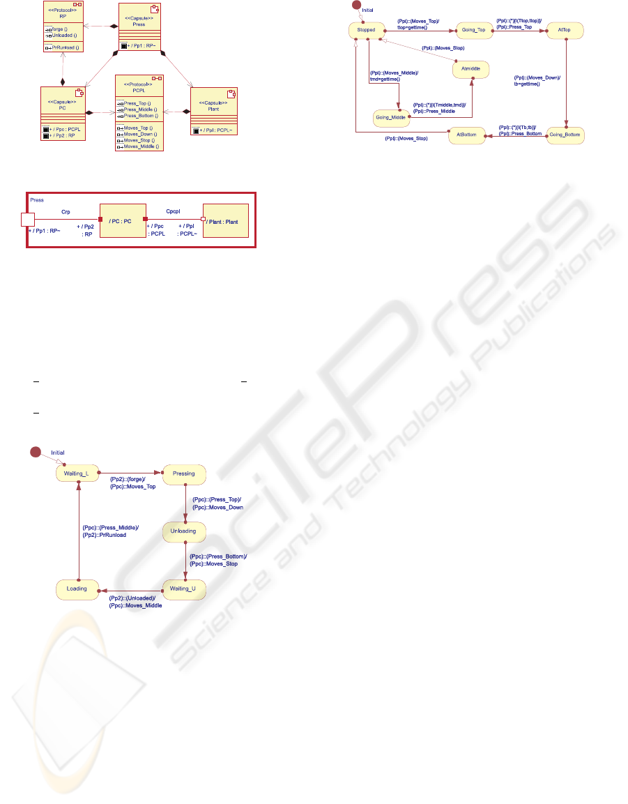
Figure 2: Press architecture – Class Diagram.
Figure 3: Press composition – Structure diagram.
receive events and to send actions to the subcapsule
Plant. Thus, a change of state in the PC UML–RT
SM is provoked by the reception of events sent by
the Press or by the Plant. (i.e., the reception of the
event forge from the Press changes the state from
Waiting
L to Pressing, and the event Press Bottom
from the Plant changes the state from Unloading to
Waiting U). Figure 4 shows the SM that models the
PC behaviour.
Figure 4: PC behaviour – State machine diagram.
In its turn, the Plant subcapsule has one port
through which it receives command from the PC to
move down, to move up or to stop, and through
this port too it sends positional information when the
Plant is placed in the bottom, middle or top position,
respectively. Figure 5 shows the SM that models the
Plant behaviour.
The original specification of the press was ob-
tained in previous works (Benghazi et al., 2006;
Benghazi et al., 2007; Capel et al., 2006) by applying
a methodological approach based on a set of transfor-
mational rules.
Figure 5: Plant behaviour – State machine diagram.
6.2 Checking the Behavioural
Consistency
According to (Hoare, 1985), to check whether
CSP + T
Ppc,Ppl
(SM
PC
,Cpcpl,SM
Plant
) is dead-
lock free, it is necessary to prove that
CSP+ T
Ppc,Ppl
(SM
PC
,Cpcpl,SM
Plant
)/s 6= Stop
for all s ∈ traces(CSP+ T
Ppc,Ppl
(SM
PC
,Cpcpl,SM
Plant
))
In this sense, if we take an arbitrary trace s ∈
traces(CSP + T
Ppc,Ppl
(SM
PC
,Cpcpl,SM
Plant
)), then we
can see that in all the cases there is at least one event
e ∈ α
C
(CSP+ T
Ppc,Ppl
(SM
PC
,Cpcpl,SM
Plant
)) whose oc-
currence extends the trace s; in other words, the com-
munication between the processes SM
PC
and SM
Plant
,
through the connector Cpcpl and the ports Ppc and
Ppl, is established by any event of the communica-
tion alphabet in the intersection of the process views
V
Ppc
(CSP+ T(SM
PC
) and V
Ppl
(CSP+ T(SM
Plant
)).
As regard to the second condition and according
to the trace semantics (Hoare, 1985), we must check
that τ(Cpcpl) ⊆ τ(CSP+ T
Ppc,Ppl
(SM
PC
,Cpcpl,SM
Plant
)),
i.e., every trace of Cpcpl is also a trace of
CSP + T
Ppc,Ppl
(SM
PC
,Cpcpl,SM
Plant
). Analyz-
ing the traces generated by the processes
CSP + T
Ppc,Ppl
(SM
PC
,Cpcpl,SM
Plant
) and Cpcpl,
we can see that CSP + T
Ppc,Ppl
(SM
PC
,Cpcpl,SM
Plant
)
is a refinement of the process Cpcpl; in other words,
CSP+ T
Ppc,Ppl
(SM
PC
,Cpcpl,SM
Plant
) is a more detailed
description than the one represented by Cpcpl;
thus, CSP + T
Ppc,Ppl
(SM
PC
,Cpcpl,SM
Plant
) consti-
tutes a specification closer to the intended system
implementation. This result checks the condition 2.
7 CONCLUSIONS
In this paper is presented a complete semantic spec-
ification of UML–RT analysis entities in terms of
CSP+T processes. Also, the consistency conditions of
the model obtained by applying the transformational
methodology are established.
ICEIS 2007 - International Conference on Enterprise Information Systems
210

Our methodological approach, introduced in a
previous paper, is complemented in this work with the
integration of a complete semantic set of the UML–
RT analysis entities and the consistency conditions
required to assure that the system obtained fulfills the
time constraints modeled in UML–RT. This new con-
tribution make more complete our method since we
systematically obtain a detailed system specification
from an initial UML model of high level of abstrac-
tion and the software engineer can verify his/her work
at any time across the development process.
The future and ongoing work is aimed at the ap-
plication of the methodological approach in other
RTS cases, researching in–depth about the verifica-
tion of these specifications, and the integration of our
methodological approach with tools as FDR.
REFERENCES
Benghazi, K., Capel, M., and Holgado, J. (2006). De-
sign of real-time systems by systematic transforma-
tion of UML-RT models into simple timed process al-
gebra system specifications. Proc. 8th International
Conference on Enterprise Information Systems (ICEIS
2006), pages 290–297.
Benghazi, K., Capel, M., Holgado, J., and Mendoza, L. E.
(2007). A methodological approach to the formal
specification of real-time systems by transformation
of UML-RT design models. Science of Computer Pro-
gramming, 65(1):41–56. Special Issue Methods of
Software Design: Techniques and Applications.
Bolognesi, T. and Brinksma, E. (1987). Introduction to the
iso specification language lotos. Comput. Netw. ISDN
Syst., 14(1):25–59.
Capel, M., Mendoza, L., Benghazi, K., and Holgado, J.
(2006). A semantic formalization of UML–RT mod-
els with CSP+T processes applicable to real-time sys-
tems verification. Actas XV Jornadas de Ingenier
´
ıa
del Software y Bases de Datos (JISBD 2006), 1:283–
292.
Cheng, B. and Wang, E. (2002). Formalizing and integrat-
ing the dynamic model for object-oriented modeling.
IEEE Trans. Softw. Eng., 28(8):747–762.
Engels, G., Heckel, R., and K
¨
uster, J. (2001a). Rule-Based
Specification of Behavioral Consistency Based on the
UML Meta-model, Lecture Notes in Computer Science
2185: UML 2001, pages 272–286. Springer-Verlag,
Berlin.
Engels, G., K
¨
uster, J., and Groenewegen, L. (2003). Consis-
tent interaction of software components. Transactions
of the SDPS: Journal of Integrated Design & Process
Science, 6(4):2–22.
Engels, G., K
¨
uster, J., Heckel, R., and Groenewegen, L.
(2001b). A methodology for specifying and analyz-
ing consistency of object-oriented behavioral mod-
els. Proc. 8th European Software Engineering Con-
ference, pages 186–195.
Evans, A., France, R., Lano, K., and Rumpe, B. (1998).
Developing the UML as a formal modelling notation.
Proc. UML’98 - Beyond the Notation, pages 297–307.
Haugen, O., Husa, K., Runde, R., and Stolen, K. (2005).
STAIRS towards formal design with sequence dia-
grams. Software & System Modelling, 00:1–13.
Hoare, C. (1985). Communicating Sequential Processes.
International Series in Computer Science. Prentice-
Hall International Ltd., Hertfordshire UK.
Kim, S.-K. and Carrington, D. (1999). Formalizing the
UML Class Diagram Using Object-Z, Lecture Notes
in Computer Science 1723: UML 99 - The Unified
Modeling Language: Beyond the Standard, pages 83–
98. Springer-Verlag, Berlin.
Lilius, J. and Porres, I. (1999). The Production Cell: An
Exercise in the Formal Verification of a UML model,
volume 288 of TUCS Technical Report. Turku Centre
for Computer Science, Finland.
OMG (2004). UML Superstructure Specification - version
2.0. Object Management Group, Massachusetts, USA.
Schneider, S. (2000). Concurrent and Real-time Systems -
The CSP Approach. John Wiley & Sons, Ltd., Chich-
ester, England.
ˇ
Zic, J. (1994). Time-constrained buffer specifications in
CSP+T and Timed CSP. ACM Transaction on Pro-
gramming Languages and Systems, 16(6):1661–1674.
CHECKING BEHAVIOURAL CONSISTENCY OF UML-RT MODELS THROUGH TRACE-BASED SEMANTICS
211
