
Binary Collaboration Models related to Manual Activities
Giorgio Bruno
Dip. Automatica e Informatica, Politecnico di Torino, Torino, Italy
Abstract. The operational implications of manual activities in business proc-
esses lead to an interesting case study on binary collaborations in which situa-
tions of clashing interactions appear. This paper analyzes three situations in-
volving manual activities and proposes three collaboration patterns to deal with
them. These patterns are presented by means of a notation based on colored
Petri nets in which most transitions are related to interactions. A solution to the
problem of clashing interactions is illustrated as well.
1 Introduction
Collaboration models are meant to specify how a number of participants have to in-
teract in order to achieve a common goal. Binary collaboration models are concerned
with the interactions taking place between two participants and they can be the start-
ing point for building multi-party collaboration models, as discussed in [1].
Various approaches and notations have been proposed, but they basically fall into
two categories: 1) a collaboration model can be presented from the point of view of
one participant (the point of view of the other participant being complementary), and
hence it is made up of communication actions (i.e. sending actions and receiving
ones); 2) or it can be formalized from a neutral perspective based on interactions. An
interaction is a kind of abstract entity as in reality it encompasses a sending action on
one side and a receiving action on the other side. Behavioral interfaces [2] belong to
the first category, while UMM [3] and WS-CDL [4] fall in the second one.
In both cases a collaboration models consists of a number of communication enti-
ties (communication actions or interactions) placed in a suitable control structure. For
this reason, in principle, the structure of collaboration models is similar to that of
business processes and the results, such as the workflow patterns [5], obtained from
the study of the latter can be applied to the former as well.
This paper analyzes the collaboration taking place between two major components
of a process-driven information system, i.e. the Process Manager (PM) and the Task
Manager (TM). A process-driven information system, also referred to as a PAIS
(Process-Aware Information System [6]), is basically an information system equipped
with business processes, which specify the order in which manual activities and auto-
matic ones have to be performed. Business processes are formal descriptions to be
interpreted by PM which, in fact, orchestrates their execution by calling the services
of the underlying information system (for the automatic activities) and by interacting
with TM for the manual activities. TM is in charge of mapping the manual activities,
Bruno G. (2007).
Binary Collaboration Models related to Manual Activities.
In Proceedings of the 1st International Joint Workshop on Technologies for Collaborative Business Processes and Management of Enterprise
Information Systems, pages 3-12
DOI: 10.5220/0002421100030012
Copyright
c
SciTePress

as seen by PM, to actual tasks, as seen by the users, and of notifying PM of the results
provided by such tasks.
This paper analyzes three situations involving manual activities, from the point of
view of the collaboration between PM and TM, and proposes three collaboration
patterns addressing these situations. Such patterns are presented by means of a nota-
tion based on colored Petri nets [7], in which most transitions are related to interac-
tions.
These patterns show circumstances in which two or more transitions are enabled
and they refer to interactions in opposite directions; this means that the participants
may take different paths and, as a consequence, they will produce clashing interac-
tions. This paper presents an approach, based on priorities, which enables the partici-
pants to reconcile.
The organization of this paper is as follows: section 2 introduces the notation used
for collaboration models and explains how to deal with clashing interactions; section
3 presents the collaboration patterns between PM and TM; section 4 makes a com-
parison with related work; section 5 presents the conclusion.
2 Modeling Binary Collaborations
This section introduces the notation used in this paper to represent binary collabora-
tions.
A binary collaboration takes place between two participants (i.e. two business
processes), which are abstractly referred to as the left participant (LP) and the right
one (RP). The reason for these terms is that binary collaborations are usually exempli-
fied by means of UML sequence diagrams having exactly two roles, one on the left
and the other on the right.
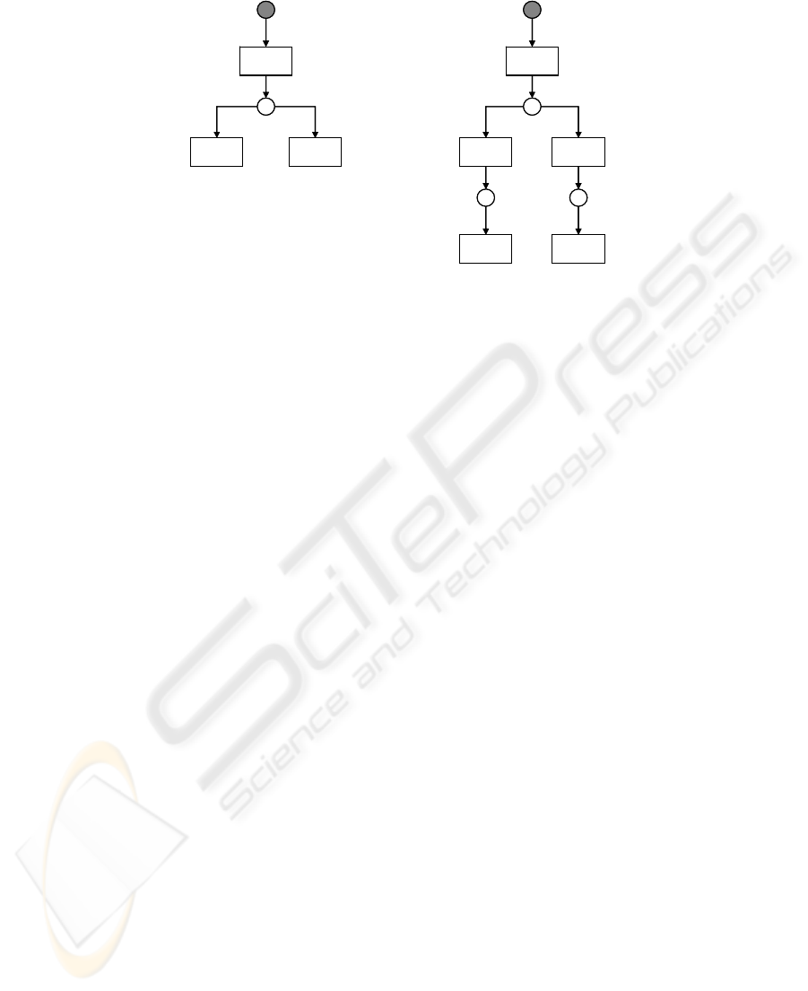
The notation is based on a special kind of colored Petri nets [7], called i-nets, as
shown in the examples presented in Figure 1. Transitions fall into two categories:
regular transitions and interaction-oriented ones. In Figure 1, only interaction-
oriented transitions appear. Interactions can be one-way or two-ways, although only
the first category appears in this paper. A one-way interaction indicates the name of
the message and its direction. For example, transition t1 contains interaction a fol-
lowed by a right arrow (Æ): this indicates that the interaction is initiated by LP,
which sends message a to RP. The left arrow (Å) indicates that the interaction is
initiated by RP. The description of messages is omitted for the sake of simplicity. The
initial node is connected to the first transition.
Binary collaboration models can be interpreted as abstract behavioral models of
the participants as far as the interactions are concerned. In fact, in the model shown in
Figure 1.a, LP is assumed to send a and then wait for either b or c, while RP is as-
sumed to receive a and then send either b or c. Therefore LP makes the first move (by
sending a) and RP makes the second one (by sending b or c). Both participants follow
the same path in the net and take the lead in turn.
4
a Æ
b Å c Å
p1
a Æ
b Å c Æ
p1
x Æ y Å
p2 p3
(a)
(b)
t1
t2 t3 t2 t3
t4 t5
Priorities: t2 > t3.
t1
a Æ
b Å c Å
p1
a Æ
b Å c Æ
p1
x Æ y Å
p2 p3
(a)
(b)
t1
t2 t3 t2 t3
t4 t5
Priorities: t2 > t3.
t1
Fig. 1. Examples of collaboration models.
There are situations, however, in which the participants may take different paths at a
fork and, as a consequence, they will produce clashing interactions.
A fork is a situation (more specifically, a marking in the net) in which two or
more transitions are enabled. If they refer to interactions in the same direction (such
as t2 and t3 in Figure 1.a), all of them are initiated by the same participant: this par-
ticipant makes the choice, and the other one follows.
On the contrary, if there are two or more transitions enabled and they refer to in-
teractions in different directions (such as t2 and t3 in Figure 1.b), both participants
may initiate an interaction at the same time, thus taking different paths.
A way of reconciling the participants is needed; this is based on the priorities
given to the clashing transitions, as discussed with the help of Figure 1.b. From place
p1, the two participants may follow different paths: RP may decide to send b at the
same time as LP is sending c.
The clash can be detected in several ways: for example, if each message is fol-
lowed by an ack from the receiver, the clash is detected by RP, if it receives c instead
of ack(b) after sending b, and by LP, if it receives b instead of ack(c) after sending c.
If the priority is given to message b, as shown by means of annotation “t2 > t3”, the
right path is the one taken by RP, so LP is to abandon its path and accept interaction
b. In this example, RP turns out to be the winner, while LP is the loser.
As to message c, which has actually been sent by LP and received by RP, there
are two ways of handling it: it can be accepted anyway or it can be rejected. In the
first case, RP is meant to process message c, while in the second case, RP will ignore
message c and LP will undo the actions related to the production of c. The first be-
havior is the standard one; the second behavior is indicated by a “-” following the
lower-priority transition. Therefore if the annotation in Figure 1.b were “t2 > t3-”,
message c, in case of clash, would be completely ignored.
The annotation must establish the priorities for all the clashing transitions in the
net.
5

A particular function of colored tokens in i-nets is to manage the correlations
among the messages, as follows. A collaboration model, such as the one in Figure 1.a,
exists in several instances, in the sense that several collaborations of that kind can
take place simultaneously between the same pair of parties. For example, at a given
instant, party A has sent a number of messages a to party B, while no message b has
been sent yet; this means that several transitions t1 have been performed and several
tokens are in place p1. When party B replies with a message b, which a is this b a
reply to?
The solution adopted in i-nets is based on correlation values carried with the mes-
sages. When a transition receives a message, it reads the correlation value from the
message and sets the correlation attributes in the outgoing tokens. Therefore, when
transition t1 receives a message a, it delivers a token to place p1 having its correlation
attribute equal to the value read from message a. When transition t2 receives a mes-
sage b, it matches the message with the proper input token on the basis of the correla-
tion value of b and the correlation attributes of the tokens in p1, and removes that
token from p1.
The standard color is called CC (correlation color): it has no additional attributes
and is omitted from the models for the sake of simplicity.
3 Collaboration Patterns
A business process is a collection of interrelated activities which fall into three major
categories: manual activities, automatic activities and control-flow ones.
A manual activity is carried out by a specific (human) user with the help of a suit-
able GUI (graphical user interface). The “task” term is often used to denote a manual
activity as perceived by the user in charge of it. A task encompasses all the low-level
interactions a user has to carry out through the GUI (e.g. entering textual information,
selecting items from lists, giving commands) in order to achieve a particular purpose,
such as placing an order.
Automatic activities are carried out without human intervention. Control-flow ac-
tivities are special automatic activities which control the flow of action; decision
nodes, merge nodes, fork nodes and join ones are common examples.
There are several notations and XML-based languages addressing business proc-
esses: the former include BPMN [8], while the latter include XPDL [9].
In traditional information systems (i.e. those in which processes are not explicitly
defined) a user can select the task to carry out through a menu showing all the possi-
ble tasks compatible with his/her role. In a process-driven information system, there
is a new category of tasks, called process-driven tasks, corresponding to the manual
activities defined in the business processes. Such tasks are usually presented to the
user in a list, called to-do list showing the name of the task as well as some specific
information.
From a logical point of view, three major software components are involved in the
operation of a process-driven information system: the Process Manager (PM), the
Task Manager (TM) and the Enterprise Information System (EIS). PM interprets the
business processes (e.g. their XML representations) and orchestrates them by interact-
6
ing with TM and EIS. EIS is a conceptual entity encompassing all the software com-
ponents needed to operate on the underlying business objects. In order to perform an
automatic activity, PM requests a service of EIS, since a business process has limited
processing capabilities. When a manual activity has to be carried out, PM requires a
service of TM, so as to include the task description in the performer’s to-do list.
Manual activities indicate the rule for selecting the performer (i.e. the user ap-
pointed to fulfil the task). In most cases, the performer is selected among the users
playing a certain role, often on the basis of a load-balancing criterion. However, there
are situations in which the selection depends on the information flow: for example,
the performer of task “accept order” is the account manager of the client organization
that issued the order to be examined. The resource patterns presented in [10] provide
a number of techniques for the selection of the performer.
This section analyzes three situations involving manual activities, from the point
of view of the collaboration between PM and TM, and proposes three collaboration
patterns addressing these situations.
In the models below, PM is the left participant and TM the right one.
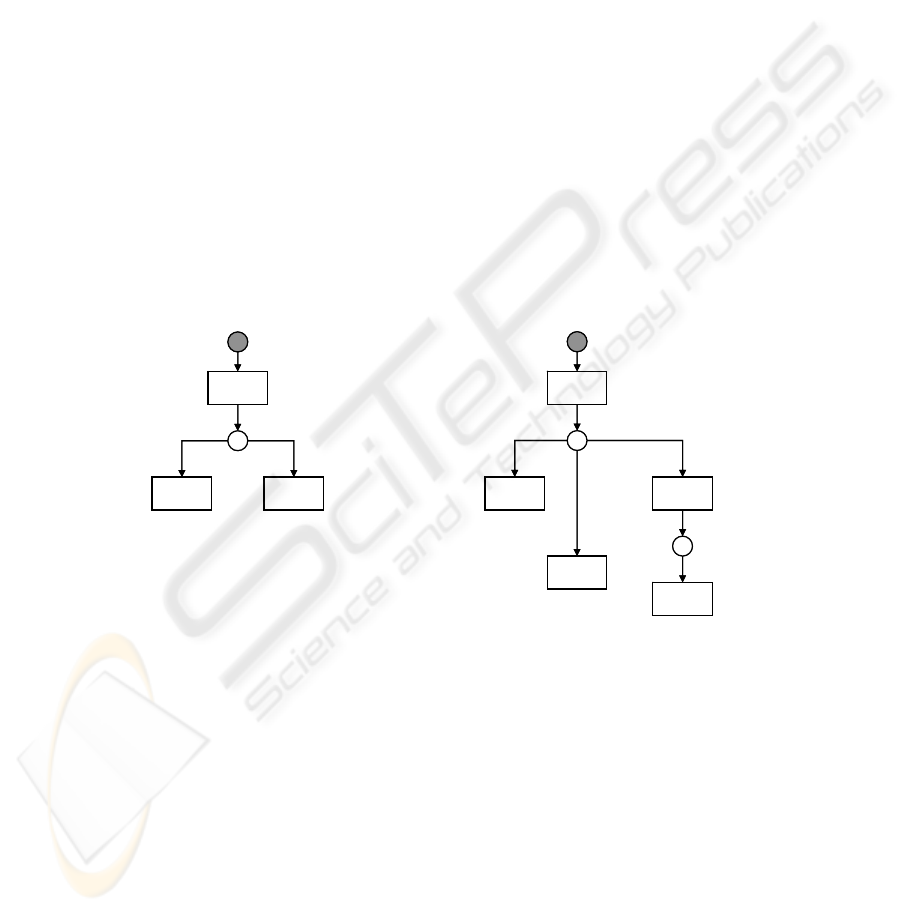
Pattern SASR (Single Activity – Single Result)
This is the most frequent case, in which a manual activity corresponds to a single
task. For example, activity “accept order” brings about a task for a single performer
(i.e. the account manager of the client organization that issued the order).
pa Æ
ap Å
anp Å
c Æ
cd Å
pa Æ
ap Å anp Å
p1
p2
(a) (b)
Priorities: t2 > t3-, t4 > t3-.
t1
t2
t3t2
t3
t1
t4
t5
p1
pa Æ
ap Å
anp Å
c Æ
cd Å
pa Æ
ap Å anp Å
p1
p2
(a) (b)
Priorities: t2 > t3-, t4 > t3-.
t1
t2
t3t2
t3
t1
t4
t5
p1
Fig. 2. Collaboration pattern SASR.
Two models are shown in Figure 2, the first is the basic one, and the second exhibits
clashing transitions due to cancellation message c.
In the first model, shown in Figure 2.a, PM starts the collaboration by sending
message pa (perform activity), then waits for either message ap (activity performed)
or message anp (activity not performed) to come.
The parameters of message pa include: the name of the task, the performer, the
business objects to be acted on, and the deadline. The parameters of the other mes-
sages are omitted for the sake of simplicity. The meaning of message ap is that the
7
activity required has been successfully performed and a result has been produced: the
information on the result is returned in the message. Message anp returns the reason
why the task has not been performed (e.g. deadline elapsed or user’s refusal).
In the second model, shown in Figure 2.b, PM can send cancellation message c so
as to make TM cancel the task, and TM replies with message cd (cancellation done).
However TM may be sending message ap (or message anp) at the same time as PM is
sending message c, so a clash may happen. In this case, as the annotation gives prior-
ity to messages ap and anp, the cancellation message is ignored and the collaboration
ends normally.
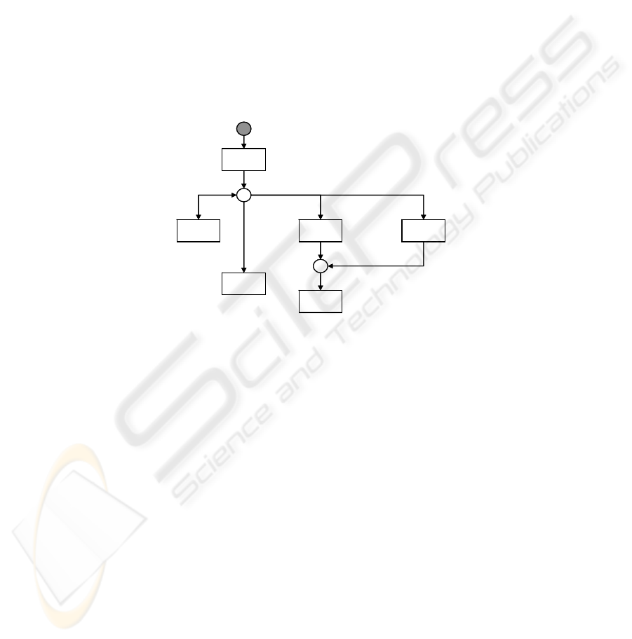
Pattern SAMR (Single Activity – Multiple Results)
As an example, manual activity “review paper” is meant to make a conference paper
reviewed by a number of reviewers (those associated with the paper). TM will pro-
duce several actual tasks, one for each reviewer involved, and will notify PM of each
review produced.
pa*Æ
dr Å
a*pÅ
c Æ
cd Å
p1
p2
ta Æ
Priorities: t3 > t2, t4 > t2, t5 > t3-, t5 > t4-.
t2 t3
t1
t4
t5
t6
pa*Æ
dr Å
a*pÅ
c Æ
cd Å
p1
p2
ta Æ
Priorities: t3 > t2, t4 > t2, t5 > t3-, t5 > t4-.
t2 t3
t1
t4
t5
t6
Fig. 3. Collaboration pattern SAMR.
The model presented in Figure 3 shows that the collaboration is started by message
pa* (perform activity with multiple results) and is normally followed by a number of
messages dr (deliver result) and one final message a*p (activity performed). How-
ever, at any time, PM can decide to cancel the whole activity or only the remaining
tasks (if it does not want to receive any more results): in the first case it will send
message c, in the second case message ta (terminate activity). On the basis of the
priorities presented in Figure 3, if a clash occurs between message dr and messages c
or ta, dr is accepted by PM, but TM follows the path chosen by PM and replies with
message cd; on the other hand, if a clash occurs between message a*p and messages c
or ta, message a*p prevails and the collaboration ends normally.
8
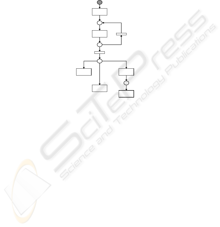
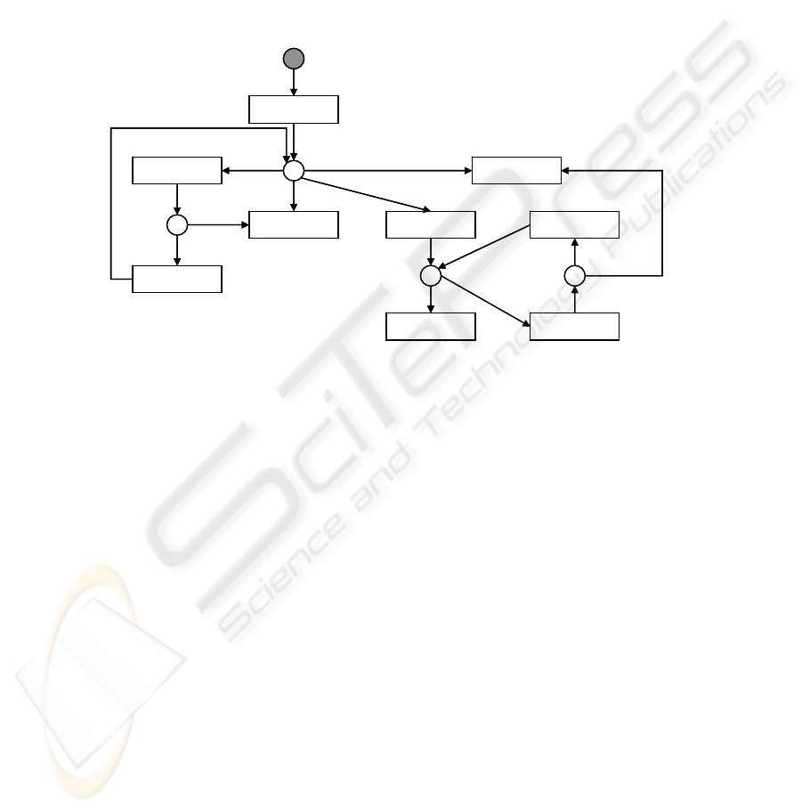
Pattern AASR (Alternative Activities – Single Result)
This pattern addresses situations in which several activities are possible, but as soon
as one is started, the others are disabled. For example, if the activity of charging an
expense, such as a travel expense, to a project is being performed, the activity of
closing the project has to be disabled and vice versa. Such situations are also known
as deferred choices [5].
paa Æ
t2
t1
t5
pa Æ
ap Å
anp Å
c Æ
cd Å
t7
t6
t3
t4
t8
Priorities: t5 > t7-, t6 > t7-.
p1, I
p2, I
p3
p4
paa Æ
t2
t1
t5
pa Æ
ap Å
anp Å
c Æ
cd Å
t7
t6
t3
t4
t8
Priorities: t5 > t7-, t6 > t7-.
p1, I
p2, I
p3
p4
Fig. 4. Collaboration pattern AASR.
The collaboration is started by message paa (perform alternative activities) and is
followed by a number of messages pa, one for each alternative activity. Places p1 and
p2 are colored and color I includes an integer value counting the number of messages
pa to be transmitted. Transitions t3 and t4 are regular transitions and the inscriptions
on their arcs are omitted. The subnet originating from place p3 is similar to the one
originating from place p1 in Figure 2 and therefore they have similar interpretations.
4 Comparison with related Work
Collaborations are based on interactions (either one-way interactions or two-way
ones). The RosettaNet consortium [11] provides a rich catalog of (business) interac-
tions including the specification of the business documents to be exchanged and of
the quality of service requirements.
Collaboration models include control-flow elements, besides the interactions. The
UMM [3] modeling methodology represent collaboration models, called business
collaboration protocols, as UML activity diagrams and provides four control-flow
elements: decision, merge, fork and join. Well known XML representations based on
9
interactions are the Business Process Specification Schema (BPSS) [12] and WS-
CDL [4].
A recent notation, “Let’s Dance” [13], proposes an original control-flow structure
based on three binary relationships, called precedence, weak precedence and inhibi-
tion.
None of the above mentioned notations and languages tackles the issue of clashing
interactions.
The Language Action perspective [14] criticizes the interactions, as conceived by
the above mentioned notations and languages, for being too rigid and adds a conver-
sational structure enabling the parties to communicate in search of mutual agreement.
rfq
Æ
rc
Æ
pc
Å
cancel
Æ
quote
Å
decline
Å
ack
Æ
quote
Å
p1
p3p2
Priorities: t3 > t2-, t3 > t4-, t3 > t5-.
t1
t2
t3
t4
t5 t6
t7 t8
rfq
Æ
p4
t9
rfq
Æ
rc
Æ
pc
Å
cancel
Æ
quote
Å
decline
Å
ack
Æ
quote
Å
p1
p3p2
Priorities: t3 > t2-, t3 > t4-, t3 > t5-.
t1
t2
t3
t4
t5 t6
t7 t8
rfq
Æ
p4
t9
Fig.5. A conversational model based on i-nets.
The “conversation for action” approach [15], based on speech act theory [16], repre-
sents a conversation as a state model between two roles, referred to as the requester
and the provider.
An example of conversational state model is shown in Figure 5 with i-nets.
The requester initially sends a request for quote (rfq) and then the provider may
decline, or reply with a quote or request a clarification (pc). In the last case, the re-
quester can provide a new rfq or terminate the conversation (cancel); the new rfq is
assumed to contain the reply to the clarification request. After receiving a quote, the
requester can acknowledge it (ack), or request a clarification (rc); in the latter case,
the provider may send a new quote or decline; the new quote is assumed to contain
the reply to the clarification request. Before receiving the first quote, the requester
may terminate the conversation (cancel), and this implies a situation of clashing inter-
actions as shown in Figure 5.
The annotation gives priority to message cancel which prevails over messages pc
and decline in case of a clash.
10

5 Conclusion
This paper has presented a notation (i-nets) based on colored Petri nets in order to
cope with the collaboration needed between two major components of a process-
driven information system, i.e. the Process Manager (PM) and the Task Manager
(TM).
Three collaboration patterns, related to the implementation of manual activities,
have been presented. These patterns show circumstances in which two or more transi-
tions are enabled and they refer to interactions in opposite directions; this means that
the participants may take different paths and, as a consequence, they will produce
clashing interactions. This paper has presented an approach, based on priorities,
which enables the participants to reconcile.
Current work is being devoted to taking advantage of the expressive power of i-
nets in order to extend the interactions presented in this paper with conversational
features, on the basis of the Language Action perspective.
Acknowledgements
The author would like to thank the reviewers for their helpful suggestions.
References
1. Bruno Giorgio, Bruno Giulia, La Rosa, M.: On Collaborations and Choreographies. Proc.
1st Int. Workshop on Technologies for Collaborative Business Process Management.
INSTICC Press (2006) 3-12
2. Barros, A., Dumas, M., Oaks, P.: Standards for Web Service Choreography and Orchestra-
tion: Status and Perspectives. Lecture Notes in Computer Science, Vol. 3812. Springer,
Berlin (2006) 61–74
3. UN/CEFACT: Modeling Methodology (UMM) User Guide. Retrieved April 10, 2007,
from http://www.unece.org/cefact/umm/UMM_userguide_V20030922.pdf
4. Kavantzas, N., Burdett, D., Ritzinger, G. : Web Services Choreography Description Lan-
guage (WS-CDL), Version 1.0. Retrieved April 10, 2007, from http://www.w3.org/TR/ws-
cdl-10/
5. van der Aalst, W.M.P., ter Hofstede, A.H.M., Kiepuszewski, B., Barros, A.P.: Workflow
Patterns. Distributed and Parallel Databases, Vol. 14(2003) 5-51
6. Dumas, M., van der Aalst, W.M.P., ter Hofstede: Process-Aware Information Systems:
Bridging People and Software Through Process Technology. Wiley (2005)
7. Kristensen, L.M., Christensen, S., Jensen, K.: The Practitioner's Guide to Coloured Petri
Nets. International Journal on Software Tools for Technology Transfer, Vol. 2. Springer,
Berlin (1998) 98-132
8. OMG: Business Process Modeling Notation (BPMN), Final Adopted Specification, Febru-
ary 2006. Retrieved April 10, 2007, from http: /www.bpmn.org/
9. Workflow Management Coalition: XML Process Definition Language, Version 2.00, 2005.
Retrieved April 10, 2007, from http://www.wfmc.org
11

10. Russell, N., van der Aalst, W.M.P., ter Hofstede, A.H.M., Edmond, D.: Workflow Re-
source Patterns: Identification, Representation and Tool Support. Lecture Notes in Com-
puter Science, Vol. 3520. Springer, Berlin (2005) 216–232
11. RosettaNet, HomePage, Retrieved April 10, 2007, from http://www.rosettanet.org
12. ebXML Business Process Specification Schema (BPSS), version 1.01. Retrieved April 10,
2007, from http://www.ebxml.org/specs/ebBPSS.pdf
13. Zaha, J.M., Barros, A., Dumas, M., ter Hofstede, A.H.M.: Let's Dance: A Language for
Service Behavior Modeling. Proceedings of the 14th International Conference on Coopera-
tive Information Systems (CoopIS), Montpellier, France, October 2006
14. Te'eni, D.: The language-action perspective as a basis for communication support systems,
Comm. of the ACM, Vol. 49 (2006), 65-70
15. Winograd, T.: A Language/Action Perspective on the Design of Cooperative Work. Hu-
man-Computer Interaction, Vol. 3 (1987-1988) 3-30
16. Searle, J.R.: Speech acts. Cambridge University Press (1969)
12
