
Transformation of BPMN Models for Behaviour Analysis
Ivo Raedts, Marija Petković, Yaroslav S. Usenko, Jan Martijn van der Werf
Jan Friso Groote and Lou Somers
LaQuSo, Laboratory for Quality Software
an activity of Technische Universiteit Eindhoven and Radboud Universiteit Nijmegen
P.O Box 513, 5600 MB Eindhoven, The Netherlands
Abstract. In industry, many business processes are modelled and stored in En-
terprise Information Systems (EIS). Tools supporting the verification and vali-
dation of business processes can help to improve the quality of these business
processes. However, existing tools can not directly be applied to models used in
industry.
In this paper, we present our approach for model verification and validation:
translating industrial models to Petri nets and mCRL2, and subsequently apply-
ing existing tools on the models derived from the initial industrial models.
The following translations are described: BPMN models to Petri nets and Petri
nets to mCRL2. It is shown what the analysis on the derived models can reveal
about the original models.
1 Introduction
New laws, standards and technologies have given the use of Enterprise Information
Systems (EIS) an enormous boost. For mayor firms, the knowledge about business
processes is a mayor asset and is stored in EIS. Different firms define their business
processes using different formalisms and tools. The data in the EIS is maintained and
used by different persons within a firm and the correctness of the business processes
should be validated and verified.
A particular check that can be performed is whether processes are sound. This applies
in particular when a process describes a workflow. A workflow process is a process
having one entry point and one exit point. A process is sound if for each state that can
be reached from the initial state, a firing sequence exists that leads the system to the
final state. In a process model with formal execution semantics, these types of proper-
ties can be defined precisely, and verified automatically by tools.
Although numerous editors for creating models are used in industry, their analysis
facilities often have shortcomings. Business processes are typically specified using
other formalisms than the ones required by most existing verification tools. More-
over, most scientific tools operate on models based on modeling languages not often
used in industry.
Model transformations provide a wider range for applying model analysis on business
processes used in industry. The original models are transformed to ‘as-equivalent-as-
Raedts I., Petkovi
´
c M., S. Usenko Y., Martijn van der Werf J., Friso Groote J. and Somers L. (2007).
Transformation of BPMN Models for Behaviour Analysis.
In Proceedings of the 5th International Workshop on Modelling, Simulation, Verification and Validation of Enterprise Information Systems, pages
126-137
DOI: 10.5220/0002428801260137
Copyright
c
SciTePress
possible’ models, specified in other formalisms, enabling the use of analysis tools for
these formalisms. This can result in better insight in, and additional information
about, the quality of the original model.
Fig. 1. Model transformations.
Our analysis approach is presented in Fig. 1. First, the original models are automati-
cally transformed to Petri nets 15. Subsequently, the Petri net models can be used as
input for Petri net-based analysis tools. The Petri nets can also automatically be trans-
formed to mCRL2 8, a process algebraic language 4, after which the mCRL2 toolset
can be used.
The Business Process Modeling Notation, BPMN, 23 is a graphical notation de-
signed for both business process design and business process implementation. BPMN
presents a good case for our approach: translating BPMN models to formal standards
supported by analysis facilities.
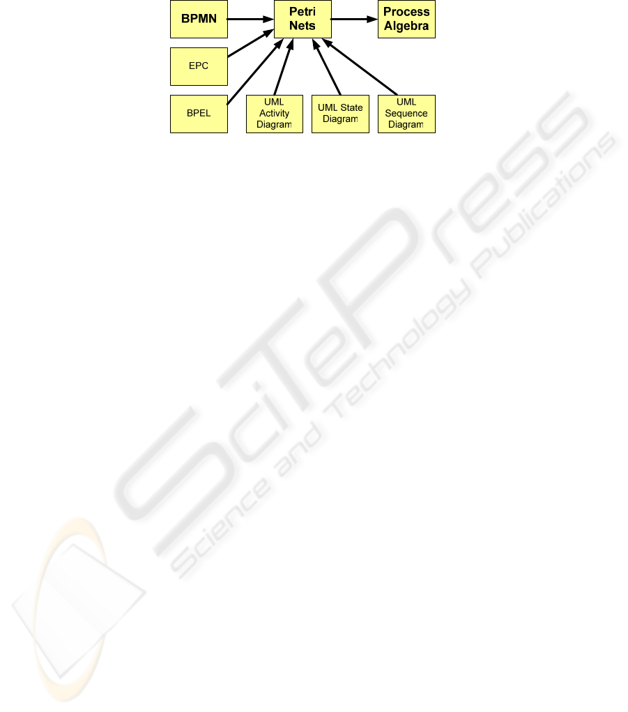
The same approach can also be followed for other industry standards, such as
BPEL 7 EPC 11 or UML diagrams 6. Transformations to Petri nets are described in
18 12 for BPEL, in 20 for EPC and in 3 for UML.
Petri nets are well-suited for modeling, analyzing and describing concurrent sys-
tems with a complex process flow. There are many Petri net-based tools like Yasper
9, Woflan 19, INA 16, LoLA 17 and CPN Tools 14 that can be used for model check-
ing and simulation. Different tools perform different types of analysis and some tools
are limited to a subset of Petri nets that can be analyzed. Therefore, it is valuable to
be able to use more tools. The range of analysis possibilities is extended by translat-
ing Petri nets to mCRL2, a process algebraic formalism. This enables automatic veri-
fication by the mCRL2 toolset.
The transformation from BPMN to Petri nets is implemented in XSLT. The trans-
formation from Petri nets to mCRL2 is implemented in C++. As both transformations
are integrated in our software framework 13 along with analysis tools, our approach
can be carried out via a web browser.
This paper is organized as follows. First the formalisms involved, BPMN, Petri
Nets and mCRL2 are explained in section 2. The transformation of BPMN models to
Petri nets is described in section 3. The Petri net-based analyses are explained in
section 4. The transformation of Petri nets to mCRL2 is described in section 5. Sec-
tion 6 shows how our analysis approach has been used in practice and what the Petri
net based analysis has revealed about the original BPMN models.
127

2 The Formalisms Involved
2.1 Business Process Modeling Notation
The Business Process Modeling Notation (BPMN) 23 is a graphical notation for busi-
ness process modeling. It describes processes in terms of order dependencies between
subprocesses and atomic tasks. The notation is supported by a variety of business
process modeling applications, and companies start to use it as their standard model-
ing technique. The BPMN standard was recently adopted by OMG 10.
Process steps are combined to processes, expressing control logic such as sequences,
choice, parallel execution and iteration. BPMN models consist of a set of nodes con-
nected by sequence flows or other types of flows. The main symbols are shown in
Table 2. An example BPMN model is shown in Figure 3.
Table 2. BPMN elements.
BPMN element Description
Start Event
Interm. Event
End Event
The Start Event indicates where a particular process will start.
Intermediate Events occur between a Start Event and an End Event
and will affect the flow of the process. The End Event indicates
where a process will end.
Task
A task is an atomic activity within the process. It represents work
to be performed. A task will be activated when one of its incoming
sequence flows is triggered and will trigger all its outgoing se-
quence flows when it is finished.
AND Gateway
An AND Gateway will trigger all outgoing flows, when all incom-
ing flows are triggered.
XOR Gateway
An XOR Gateway will trigger one of its outgoing flows when one
of its incoming flows is triggered.
Subprocess
Subprocesses are used to support hierarchy. A Subprocess contains
its own Start and End Event.
Sequence Flow
The Sequence Flow shows the order in which activities will be
performed in a Process.
2.2 Petri Nets
Petri nets provide a formal method to describe behaviour. A Petri net consists of
places and transitions, connected by directed arcs. A place can only be connected to a
transition and vice versa. In classical Petri nets, these are the only allowed elements.
The formal definition of Petri nets can be found in 14. Petri nets can be extended to
be able to express more behaviour. The Petri nets used here, further referred to as
128
extended Petri nets, are extended with inhibitor 1 and reset arcs 2. In Table 3, the
Petri net elements are explained.
Table 3. Petri net elements.
Element Description
Transition
A transition is a modeling unit representing a process step.
Place
Place with tokens
A place can contain tokens that define a part of the state of the net. A
distribution of tokens over the places is called a marking, representing
the state of the net.
Inflow Arc
An inflow arc is the arrow from a (incoming) place to a transition. If
all incoming places connected to a transition have enough tokens
according to the firing rules, the transition is enabled and can fire.
Outflow Arc
An outflow arc is the arrow from a transition to a (outgoing) place. If a
transition fires, it consumes tokens from its incoming places, and
produces tokens in its outgoing places according to the firing rules.
Reset Arc
When a place is connected to a transition with a reset arc, all tokens
are removed from it when the transition fires.
Inhibitor Arc
When a place connected to a transition via an inhibitor arc contains a
token, the transition cannot be enabled.
Yasper 9 is a Petri net modeller and simulator extending Petri nets with various no-
tions. The most important ones are shown in Table 4. Transitions are also extended
with properties dealing with timing, costs, and resources for simulation purposes.
Table 4. Yasper specific elements.
Element Description
Case sensitivity
(yellow)
Yasper distinguishes between different workflow cases in a process. This is
done with case sensitive places. Transitions having multiple case sensitive
input places can only fire if enough tokens of the same case are present. If a
transition fires, tokens produced in the case sensitive output places have the
same case identity as tokens consumed from the case sensitive input places.
Emitter
A transition, with outflow arcs to case sensitive places but without inflow
arcs from case sensitive places, is drawn differently and is called emitter.
Collector
A transition, with no outflow arcs to case sensitive places but with inflow
arcs from case sensitive places, is drawn differently and is called collector.
XOR
This element requires and consumes one token from one of the places con-
nected with an inflow arc. When the XOR fires, one token is produced in one
of the places (chosen non-deterministically) connected with an outflow arc.
Subnet
This element is used to support hierarchy.
129

2.3 mCRL2
The language mCRL2 8 offers a uniform framework for the specification of data and
processes. Data is specified by equational specifications: one can declare types and
functions working upon these types, and describe the meaning of these functions by
equational axioms. Processes are described in process algebraic style, where the par-
ticular process syntax stems from ACP 4, extended with data-parametric ingredients.
Infinite processes are specified by means of (finite systems of) recursive equations,
which can also be data-parametric. As an example, for action a, each solution for the
equation X=a.X specifies the process that can only repeatedly execute a. Here, X is a
process name and “.” is the sequential composition operator. The Process Y(23),
where Y(n) is defined by the data-parametric equation Y(n)=a.Y(n+1), can do the
same as X.
mCRL2 makes use of multiactions. A multiaction is a collection of ordinary actions
that happen simultaneously as one atomic step. A few examples of multiactions are
a|b, a|b|c and a|a|b. The multiactions are convenient for representing Petri nets be-
cause several actions may be performed synchronously when a transition is being
fired, like removing a token from an input place and adding a token to an output
place. These actions are combined to a multiaction and then hidden in a way that only
the transition name is left visible.
In mCRL2 parallel composition does not communicate. Instead, it introduces multiac-
tions, e.g. the parallel composition a||b of actions a and b is equal to a.b+b.a+a|b,
where + is the alternative composition operator. As a result, the number of multiac-
tions can increase exponentially with the number of parallel compositions. Hence,
operators need to restrict this behaviour. The blocking operator block(H,p) blocks all
multiactions a part of which occurs in the action set H, on the process p. For example:
δ
δ
δ
..))|.(},({ bbcabaablock
=
+=
+
where
δ
is a deadlock process that cannot
execute any action.
Communication of actions is also defined using the concept of multiactions. The local
communication operator comm(C,p) realizes communication of multiactions with
equal data arguments. For instance, comm({_a|a
→__a}, a|_a|c|d) = __a|c|d.
3 Transforming BPMN Models to Petri Nets
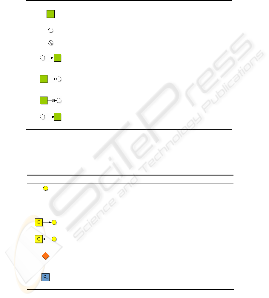
The mapping rules for the translation of BPMN to Petri nets are shown in Table 5. If
the resulting Petri nets do not contain reset or inhibitor arcs, most Petri net tools can
be used to analyze the translated BPMN models. The last translation rule in the table
illustrates how a time-out exception is translated. An example of the mapping is
shown in Figure 3. The translation is described in detail in 21.
130
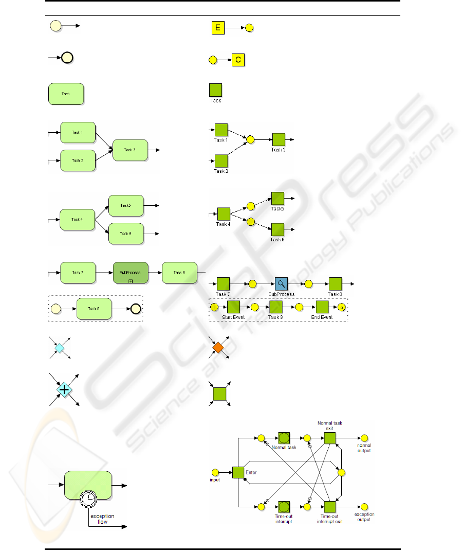
Table 5. The mapping between BPMN and Petri nets.
BPMN elements Petri net elements
Start Event
Emitter connected to place
End Event
Place connected to Collector
Task
Transition
Task with two incoming sequence flows
Merge-like behaviour
Task with two outgoing sequence flows
Fork-like behaviour
A connected Subprocess
A connected Subnet
XOR Gateway
XOR
AND Gateway
Transition
Time-out interruptible task
The translation result of the time-out interruptible
task
131
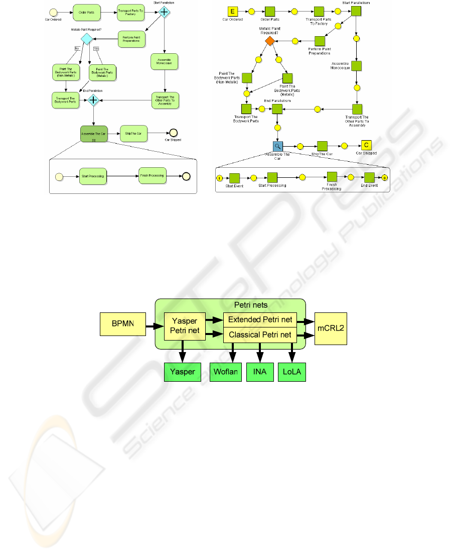
Fig. 3. An example BPMN model and the derived Petri net.
4 Analyzing Industrial Models using Petri Net-based Tools
Figure 4 depicts the Petri net analyzers and transformations from, to, and between
Petri nets we use.
Fig. 4. Petri net analysis tools and related transformations.
4.1 Yasper
After the transformation of a BPMN model to a Yasper Petri net, Yasper simulations
on the derived Petri net can be used to validate the original model.
Yasper supports automatic simulation, where the transitions to execute are randomly
chosen. Transitions can have a mean execution time and deviation and both fixed
costs and costs per time unit. The automatic simulation uses this information to pro-
vide performance analysis by simulation.
Another facility is the stepwise execution of a net. At each step, the user can select
one of the enabled transitions to execute, after which the state (i.e. the distribution of
tokens) is updated accordingly. This manual simulation helps users to validate their
132

models by enabling them to quickly explore many different process execution paths
and discover that unexpected or incorrect states are reachable.
The Yasper Petri net editor and analysis tool 9 can assist with soundness verification
in several ways. Yasper provides reduction techniques 22 preserving properties like
soundness and liveness. These reductions result in a smaller model which is easier to
analyse.
4.2 Woflan, INA and LoLA
In order to invoke automatic verification tools, like Woflan, INA, and LoLA, the
Yasper Petri nets are transformed to classical Petri nets. This can only be done if the
net does not contain reset arcs or inhibitors.
Woflan 19, the Workflow Analyzer, is a software tool with the specific purpose of
analyzing workflow Petri nets for soundness. Applied to a net it reports whether the
net is a valid workflow net, and if so, whether it is sound; if not, it lists one or more
specific problems with the net.
INA 16, the Integrated Net Analyzer, provides traditional Petri net analysis on
classical Petri nets: it can check a number of Petri net properties and show the invari-
ants, the reachability and the coverability graphs of a Petri net. INA also offers model
checking with temporal logic on Petri nets to verify properties of the system.
LoLA 17 is a model checking tool which tackles the state space explosion by us-
ing reduction techniques. Therefore, INA is first used to check the Petri net, and then
LoLA is used to verify properties on the system.
5 Petri Nets to mCRL2
If the Petri net contains reset arcs or inhibitor arcs, most Petri net tools cannot be
used. In this case, our solution is transforming the extended Petri net to mCRL2, to
enable automatic verification.
Petri nets are input to the transformation to mCRL2 specifications. Petri nets consist
of a finite set of places {P
1
,...,P
n
}, transitions {T
1
,...,T
m
}, and arcs {a
1
,...,a
k
, a'
1
,…,a'
l
}
that connect places to transitions (inflow arcs), and vice versa (outflow arcs). The arcs
may be ordinary, inhibitor or reset arcs. Besides the Petri net itself, also the initial
marking of the Petri net is used for the translation to mCRL2.
133
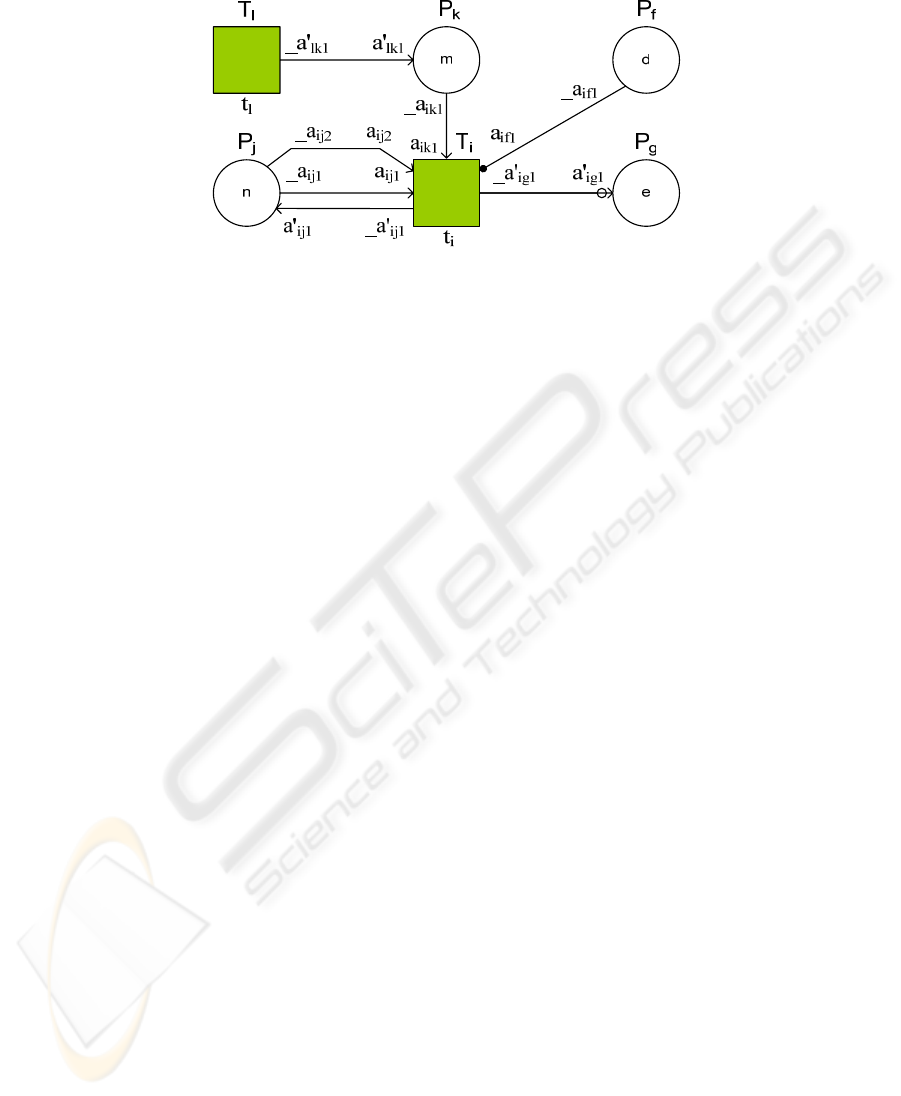
Fig. 5. mCRL2 actions mapped to the arcs and transitions of a Petri net.
As illustrated in Figure 5 the result of the transformation, a mCRL2 specification, is
constructed in the following way:
Each arc is represented by three actions in mCRL2: a and _a represent the outflow
actions and the inflow actions associated with the arc, and __a represents their syn-
chronization where __a = a|_a.
Each transition T
i
is represented by the process
iipxiipxii
taaaaT |'||'|_||
1111
KK=
where a
i11
,...,a
ipx
are the inflow arcs that enter T
i
and _a'
i11
,...,_a'
ipx'
are the outflow
arcs that depart from T
i
. Action t
i
is used to indicate that transition T
i
has fired.
Each place P
j
is represented by the process equation
∑
∈
+−→≥=
},,1{
),('1),(1
)),('),((.'||'|_||_)),(():(
qi
jjiijpijjiijpijj
jipjipnPaaaajipnNatnP
K
KK
where q is the number of different transitions connected to P
j
by an arc, and the ac-
tions _a
ijx
and a'
ijx
are the inflow and the outflow actions corresponding to the inflow
and outflow arcs connecting place P
j
and transition T
i
, respectively. The parameter n
represents the amount of tokens P
j
contains, p(i,j) is the number of inflow arcs from
P
j
to T
i
, and p'(i,j) is the number of outflow arcs from T
i
to P
j
.
In case of inhibitor arcs we check if the adjacent place is empty using the condition
n=0 in the above process equation. In case of reset arcs we set the number of tokens
to be the number of incoming arcs by changing the recursive call to P
j
(p'(i,j)) in the
above process equation.
All transitions are combined in one process T = (T
1
+...+T
m
).T which represents that
the transitions must be interleaved, and do not happen simultaneously.
The whole system is represented by the parallel composition of all processes repre-
senting places, where the actions representing arcs are forced to synchronize:
S = hide({__a},block({a,_a},comm({a|_a→__a},P
1
||...||P
n
||T)))
The arc firing actions are hidden, which only leaves the t
i
actions visible. This shows
when a particular transition fires.
134

5.1 Analyzing Petri Nets using the mCRL2 Toolset
The mCRL2 toolset allows to generate a transition system (state space) corresponding
to the generated mCRL2 specification derived from the Petri net. The labels of this
transition system represent the firings of the transitions of the Petri net. Each path in
the generated transition system can be simulated with Petri net simulation tools. The
mCRL2 toolset can automatically find deadlock traces starting from the system’s
initial state and resulting in a state from where no transitions are enabled.
Furthermore, the mCRL2 toolset can visualize the state spaces. This can be used to
find livelock-states from which it is possible to keep repeating the same set of activi-
ties, but from which it is impossible to perform a sequence of activities that lead the
system to the desired final state.
6 Case Study
One of our clients is maintaining business processes related to various sectors. Educa-
tion is one of these sectors and its processes are stored as BPMN models. We re-
ceived six BPMN models and performed automated error detection on these models.
We translated the BPMN models to Petri nets and subsequently invoked Woflan on
the Petri nets to perform automatic verification. The results are shown in Table 6.
Table 6. The results of the analysis of the BPMN models.
Model
number
Number of
BPMN
elements
Number of
Petri net
elements
Woflan result
1 14 26 1 AND-OR mismatch
2 41 79 No workflow (unrelated nodes)
3 17 33 Sound workflow process definition
4 73 143 2 AND-OR mismatches
5 93 176 5 AND-OR mismatches
6 62 114 No workflow (no unique start condition)
The column ‘Woflan result’ contains the summarized conclusion of Woflan.
After retrieving the results, we had to translate them back in terms of the BPMN
models to locate the errors. In the reports, Woflan printed the names of the Petri net
transitions involved in the error. Since the transition names are identical to the BPMN
task names and as the translation uses the BPMN lay-out to generate the Petri net lay-
out, it was relatively easy to locate the BPMN tasks involved.
Two of the analyzed models are no workflows and eight AND-OR mismatches
were found in the four remaining models. The AND-OR mismatches reported by
Woflan indicate that a parallel split is not matched by a parallel join, while it should
be joined by a parallel join. The unrelated nodes, indicated by Woflan in Table 6,
turned out to be a livelock. A livelock state is a state from which it is possible to pro-
135
ceed, but from which it is impossible to reach the desired final state. Table 7 shows
how the livelock and an AND-OR mismatch found in the Petri net relate to errors in
the BPMN model.
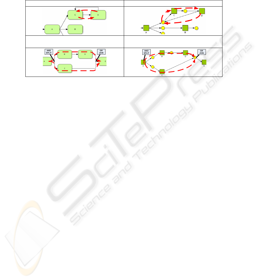
Table 7. Interpreting the analysis results.
The Livelock in the BPMN model The Livelock in the Petri net
The AND-OR mismatch in the BPMN
model
AND-OR mismatch in the Petri net
Once task A from the shown livelock is triggered, the process will reach a livelock
state. Most AND-OR mismatches were similar to the one that is shown. Two se-
quence flows leaving task A means that both task B and C will be triggered, but the
two sequence flows entering task E, result in task E being triggered twice. These
errors can be prevented by forbidding modellers to model tasks which have multiple
incoming and outgoing sequence flows. Instead gateways should be used.
7 Conclusions and Future Work
We now have an operational tool to perform BPMN model translations that we can
further extend with more advanced BPMN constructs. We have employed it on pre-
existing BPMN models in actual use, and found many actual inconsistencies with the
models, clearly pointing out the need for the modellers to improve their models be-
fore they can be used as exact specifications.
Our next goal is to be able to automatically present the Petri net and mCRL2 analysis
results in terms of the original model. For example, we want to parse deadlock traces,
which can be sequences of the elements of a Petri net model, and subsequently auto-
matically back-translate these to deadlock traces in terms of the original BPMN mod-
els. This should fasten the interpretation of analysis results to original models.
References
1. Agerwala, T.: A complete model for representing the coordination of asynchronous proc-
esses. Technical report, John Hopkins University, Baltimore, Maryland. (1974)
2. Araki, T., Kasami, T.: Some decision problems related to the reachability problem for Petri
nets. Theoretical Computer Science 3(1) (1976) 85-104
136

3. Baresi, L.; Pezzè, M.: On Formalizing UML with High-Level Petri Nets. In: Agha, G.A.;
De Cindio, F.; Rozenberg, G.: Lecture Notes in Computer Science, Vol. 2001: Concurrent
Object-Oriented Programming and Petri Nets, Advances in Petri Nets, pages 276-304.
Springer-Verlag, 2001.
4. Baeten, J.C.M., Weijland, W.P.: Process Algebra. Cambridge Tracts in Theoretical Com-
puter Science 18, Cambridge University Press (1990)
5. Billington, J., Christensen, S., Hee van, K., Kindler, E., Kummer, O., Petrucci, L., Post, R.,
Stehno, C., Weber, M.: The Petri Net Markup Language: Concepts, Technology, and
Tools. In: Proc. ICATPN 2003, Eindhoven. LNCS 2679, Springer-Verlag (2003) 483-505
6. Booch, G., Rumbaugh, J., Jacobson, I.: The Unified Modeling Language User Guide. Ad-
dison-Wesley, Reading (1999)
7. Curbera, F., Goland, Y., Klein, J., Leymann, F., Roller, D., Thatte, S., Weerawarana, S.,
Business Process Execution Language for Web Services, Version 1.0, (2002)
8. Groote, J.F., Weerdenburg van, M.J., Mathijssen, A.H.J., Usenko, Y.S.: From µCRL to
mCRL2. Motivation and outline. In: Aceto, L., Gordon, A.D. (eds.): Short contrib.. Work-
shop on Algebraic Process Calculi: The First Twenty Five Years and Beyond, BRICS
Technical Report NS-05-3 (2005) 126-131
9. Hee van, K., Post, R., Somers, L.: Yet Another Smart Process EditoR. In: Feliz-Teixeira, J.,
Carvalho Brito, A.E. (eds.): Proc. European Simulation and Modelling Conference
(ESM2005), Eurosis-ETI, Ostend, ISBN 90-77381-22-8 (2005) 527-530
10. Home page http://www.omg.org/
11. Keller, G., Nüttgens, M., Scheer, A. W., Semantische Prozessmodellierung auf der Grund-
lage "Ereignisgesteuerter Prozessketten (EPK)", Heft 89, Institut für Wirtschaftsinfor-
matik, Saarbrücken, Germany (1992)
12. Ouyang, C., Verbeek, E., Aalst van der, W.M.P., Breutel, S., Dumas, M., Hofstede ter,
A.H..: Formal Semantics and Analysis of Control Flow in WS-BPEL. Technical report (re-
vised version), Queensland University of Technology (October 2005)
13. Raedts, I., Petkovic, M., Serebrenik, A., Werf van der, J.M.E.M., Somers, L.J.A.M., Boote,
M.: A Software Framework for Automated Verification. In: Proceedings 22nd Annual
ACM Symposium on Applied Computing, Seoul, (2007) 1031-1032.
14. Ratzer, A., Wells, L., Lassen, H.M., Laursen, M., Qvortrup, J.F., Stissing, M.S., Wester-
gaard, M., Christensen, S., Jensen, K.: CPN Tools for Editing, Simulating, and Analysing
Coloured Petri Nets. In: Proc. ICATPN 2003, Eindhoven. LNCS 2679, Springer-Verlag
(2003) 450-462.
15. Reisig, W.: Petri Nets, An Introduction. Springer-Verlag, Berlin (1985)
16. Roch, S., Starke, P.: INA: Integrierter Netzanalysator, Handbuch, version 2.1. Technical
report, Humboldt-Universitaet zu Berlin (1998)
17. Schmidt, K.: LoLA: A Low Level Analyser. In: Nielsen, M., Simpson, D. (eds.): Proc.
ICATPN 2000. LNCS 1825, Springer-Verlag (2000) 465-474
18. Stahl, C.: A Petri Net Semantics for BPEL. Technical Report 188, Humboldt-UniversitÄat
zu Berlin (July 2005)
19. Verbeek, H.M.W., Basten, T., Aalst van der, W.M.P.: Diagnosing Workflow Processes
using Woflan. The Computer Journal 44(4) (2001) 246-279
20. Verbeek, H.M.W. Dongen van, B.F. : Translating labelled P/T nets into EPCs for sake of
communication, In: BETA Working Paper 194, January 2007, Eindhoven University of
Technology
21. Vijverberg, W., Translation of Process Modeling Languages, Master’s thesis, Eindhoven
(2006)
22. Werf van der, J.M.E.M.: Analysis of well-formedness and soundness by reduction tech-
niques and their implementation. Master thesis, Eindhoven (2006)
23. White, S.A.: Business Process Modeling Notation (BPMN) Version 1.0 - May 2004
137
