
A Key Management Method for Cryptographically
Enforced Access Control
Anna Zych
1
, Milan Petkovi
´
c
2
and Willem Jonker
2
1
Twente University
2
Philips Research
Abstract. Cryptographic enforcement of access control mechanisms relies on
encrypting protected data with the keys stored by authorized users. This approach
poses the problem of the distribution of secret keys. In this paper, a key manage-
ment scheme is presented where each user stores a single key and is capable of
efficiently calculating appropriate keys needed to access requested data. The pro-
posed scheme does not require to encrypt the same data (key) multiple times with
the keys of different users or groups of users. It is designed especially for the
purpose of access control. Thanks to that, the space needed for storing public
parameters is significantly reduced. Furthermore, the proposed method supports
flexible updates when user’s access rights change.
1 Introduction
Advances in information and communication technologies bring with numerous bene-
fits also concerns with respect to security issues. The data no longer resides on main-
frames physically isolated within an organization, where physical security measures
can be taken to safeguard the data and the system. Modern solutions are evolving to-
wards open, interconnected environment where storage outsourcing and operations on
untrusted servers happen frequently. Open access data storage standards pose new chal-
lenges on security technologies. The old server-centric protection model locks data in a
database server and uses a traditional access control model to permit access to data. To
facilitate current developments, a data-centric protection model is required, where data
is cryptographically protected and allowed to be outsourced or even freely float on the
network. In many cases there is a need to replicate the data and send it to the clients.
Examples are distributed databases, grid computing, enterprise rights management sys-
tems and peer-to-peer data management systems in general. Consider for example the
development of Electronic Health Records (EHRs). It aims at increased availability and
sharing of patient records. Records are shared among different healthcare providers, ex-
ternal wellness services and relatives. As the healthcare data is very sensitive, privacy
and security have to be taken care of. Today this often means that access to EHRs is
restricted to a controlled environment of care institutions. This limitation can be over-
come by the more flexible data-centric protection.
In this paper, we address the key management problem of the data-centric protection
model. Namely, when the data is encrypted, the access control policies have to be taken
into account so that control is maintained regarding which users can access what data.
Zych A., Petkovi
´
c M. and Jonker W. (2007).
A Key Management Method for Cryptographically Enforced Access Control.
In Proceedings of the 5th International Workshop on Security in Information Systems, pages 9-22
DOI: 10.5220/0002432300090022
Copyright
c
SciTePress

The remainder of this paper is organized as follows. Section 2 describes the problem
and surveys the related work. Our key management solution is presented in Section 3.
Section 4 is devoted to the problem of updates of access rights. Section 5 discusses the
advantages of the proposed solution compared to the state-of-the-art. Finally, Section 6
summarizes our contributions.
2 Related Work and Problem Description
A straightforward solution to enforce access control with cryptography is to encrypt the
data with a data key, which is consequently encrypted with the keys of users that should
be able to access this data. The drawback of such approach is that each data key is stored
in multiple copies encrypted with different user keys. The number of copies of a single
data key can reach the number of users (or roles or user groups) in the system. For large
systems that allow fine granularity of access to data, this number can by far exceed the
size of the protected data itself. Another problem is updating encrypted data keys when
the access control policies change. Thus, we search for a method to assign the keys to
the data and the users in a more efficient manner, supporting flexible updates.
There are a number of different definitions of the key management problem in the
literature. We propose here a generalized problem statement. To the best of our knowl-
edge our definition covers all the approaches presented in the literature.
Generalized Key Management Problem Let U be the set of users of the system (users
can represent individuals, roles or groups of individuals), and let D be the set of data
records. Any set of users is an access configuration. The set of users allowed to access
data record d ∈ D is an access configuration associated with d, denoted as AC(d). The
access configurations are partially ordered in a natural way via subset inclusion ⊂ (see
Figure 1c).
The inclusion partial order is used to assign the keys to groups of users. This partial
order satisfies more conditions than necessary and therefore wastes opportunities. By
relaxing these, and defining a weaker order relation, we allow partial orders that in turn
allow for more efficient key management.
The necessary conditions for the partial order (P, <) on access configurations are
as follows. For each user u access configuration {u} belongs to P : ∀
u∈U
{u} ∈ P .
There may be however some additional access configurations in P , for example AC(d)
for d ∈ D. The order relation < on elements of P satisfies (order conditions):
(
AC
1
⊃ AC
2
, |AC
2
| = 1 =⇒ AC
1
< AC
2
AC
1
< AC
2
=⇒ AC
1
⊃ AC
2
(1)
This definition ensures, that if u ∈ AC, then {u} > AC, and requires as few other
order relations as possible. Intuitively, we want to model that the data accessible by the
whole group AC is also accessible by any user u ∈ AC. Examples of orders that satisfy
our definition are presented in Figure 1.
The task of the key management scheme is to (i) design an efficient
3
partial order
P satisfying order conditions (1) and (ii) assign to each access configuration AC in P
3
By efficient we mean with minimal number of configurations and relations on them, but avoid-
ing multiple copies of data keys.
10

u1 u2 u3 u4 u5 u6 u7 u8
{ 12} { 34} { 56} { 78}
{ 1234} { 5678}
{ 12345678 }
++++++u7
++++++u8
++++++u6
++++++u5
++++++u4
++++++u3
++--++u2
--++++u1
d6d5d4d3d2d1
ACCESS RI GHTS:
AC(d3)= AC(d4)= {1345678}= {1}«{34}«{5678}
Encrypted data: E(k
d3
,d3) E(k
d4
,d4)
Encrypted keys: E(K
{1}
, k
d3
) E(K
{34}
,k
d3
) E(K
{5678} ,
k
d3
)
E(K
{1}
, k
d4
) E(K
{34}
,k
d4
) E(K
{5678} ,
k
d4
)
( a)
u1 u7 u3 u4 u5 u6 u2 u8
AC( d5) = AC( d6 )
= { 2345678}
Dum my AC:
{ 345678}
AC( d1 ) = AC(d2 ) = { 12345678}
AC( d3 ) = AC( d4 )
= { 1345678}
<
<
<
<
u1 u3 u4 u5 u6 u7 u8 u2
AC( d5 ) = AC( d6 )
= { 2345678}
AC( d3 ) = AC( d4 )
= { 1345678}
Dum my AC:
{ 345678}
AC( d1 ) = AC(d2 ) = { 12345678}
AC(d3)= AC(d4)= {1345678}
Encrypted data: E(k
d3
,d3) E(k
d4
,d4)
Encrypted keys: E(K
{1345678}
, k
d3
)
E(K
{1345678}
,k
d4
)
( b)
( c)
Fig.1. Example of an access table and orders on access configurations from this table.
on or more secret keys K
AC
, such that based on K
{u}
each user u can obtain K
AC
for every AC < {u}. The data records d ∈ D are encrypted with the data key k
d
,
that in turn is encrypted with the keys of groups of users AC
i
in such a way, that
AC(d) =
S
i
AC
i
. Thus, all the authorized users can access their data. The examples
are shown in Figure 1. In case of broadcast encryption order (Figure 1 a), the data
keys k
d
3
and k
d
4
are encrypted three times each with the keys of access configurations
that sum up to AC(d
3
) = AC(d
4
). In the two other partial orders in Figure 1 b and
c, AC(d) for each data record d ∈ D is included in the order, thus each data key is
encrypted only once.
Various solutions were proposed to address this problem [1–6]. Practical approaches
designed for cryptographically enforced access control are mostly based on broadcast
encryption [4]. In the basic approach, the users are represented by the leafs and the
access configurations are represented by the interior nodes of a binary tree. This binary
tree represents the partial order on access configurations, as shown in Figure 1a. The
user is required to store all the keys on the path from the corresponding leaf to the
root of the tree. She can decrypt all the necessary data with the keys she stores. This
strategy only partially reduces the redundancy described previously, as there are still
multiple copies of data keys. Furthermore, each user stores the number of keys that is
of order of the logarithm of the number of subjects, instead of just a single key as in the
straightforward solution.
A number of improvements of this basic method were proposed. Most of them [5,
6] consider users as stateless receivers, and are referred in the literature as revocation
schemes. The improvements are achieved by introducing more groups, more complex
orderings of these groups, and sophisticated key assignment methods.
Another popular approach constitutes of the key generation schemes [1–3]. Essen-
tially, the partial order is given, and the task of the scheme is to assign the keys to the
elements (access configurations) of the given order. In the access control settings, that
means that given the key of AC
1
and some public information one can compute the
key of AC
2
if and only if AC
2
< AC
1
. Support for an arbitrary number of groups
allows the complete elimination of the multiple copies of data keys while, thanks to key
generation mechanism, each user has only one secret key. However, the price to be paid
is the public information that is stored on a public server, used by the users to derive
keys. Especially in the case of access control, it is very important to minimize the public
space, as the size of the partial orders of access configurations can be exponential in the
number of users.
11

We discuss the key generation schemes applied to access control (as done in [7])
and compare them with our approach in Section 5.
3 Key Management Solution
In this section we propose an efficient solution for the key management problem stated
above. In Section 3.1, we present an algorithm for constructing the partial order on
access configurations (AC) satisfying (1). We represent this partial order by an acyclic
and transitively reduced directed graph, where nodes are access configurations, and arcs
(directed edges) connect comparable elements, from greater to smaller. In the literature,
such a graph is called a Hasse diagram of a partial order. We denote the presence of an
arc from x to y by x −→ y, and a directed path as x ։ y. The constructed graph has
two additional properties referred to as V-conditions:
(
The number of arcs coming into a node is either 2 or 0
For any two nodes, at most one node has arcs into both of them.
(2)
A graph satisfying (2) is a V-graph. Examples of a non V-graph (a) and a V-graph
(c) are shown in Figure 2. We refer to a transitively reduced acyclic digraph satisfying
(2) and representing an order satisfying (1) as access control graph. The V-form of
the graph allows us to apply the Diffie-Hellman (DH) based key generation scheme
presented in Section 3.2. The DH scheme assigns public and private keys to the nodes.
Each user receives a single private key and using this key he is able to derive the keys
needed to decrypt the data he has right to access.
3.1 Hierarchy Construction Algorithm
In this section we present the construction of a partial order on access configurations.
The CreateHierarchy(Access Table ACCESS) algorithm presented in this section takes
as an input an access table (as in Figure 1) and builds an access control graph on access
configurations (shown in Figure 2 c). Appendices A and B provide the code and the
correctness proof respectively.
The input access table ACCESS is a boolean matrix representing access rights
given to the users. The rows correspond to the users and the columns to the data records.
The value ACCESS[u, d] = true(+) if and only if user u is allowed to access data d.
Each column represents an access configuration of the corresponding data object.
The algorithm consists of the initial phase and the three construction phases de-
scribed below. In the initial phase, the CreateHierarchy algorithm obtains access config-
urations of all d ∈ D from corresponding columns and stores them in the priority queue
Q, with the priority of AC set to its size |AC|. Smaller configurations are extracted
earlier. Additionally, all access configurations containing a single user are inserted to
initially empty graph G.
Let In(x) for x ∈ G denote the set of directed edges (arcs) pointing to x. In the
next phases, the algorithm adds access configurations and edges to the graph. Some of
these adds may cause previously added edges to be removed. The aim of these transfor-
mations is to obtain a graph satisfying the conditions from Table 1.
12
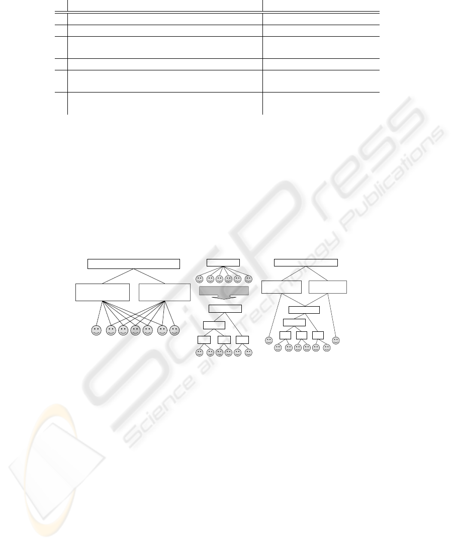
Table 1. Conditions specifying access control graph and their informal description.
Description Condition
a. Access configurations of all single users belong to G {u} ∈ G for each u ∈ U
a’. Access configurations of all data records belong to G AC(d) ∈ G for each d ∈ D
b. A user is connected via directed paths with all the u ∈ AC =⇒ {u} ։ AC
configurations she belongs to (first order condition)
b’. Second order condition AC
1
։ AC
2
⇒ AC
1
⊆ AC
2
c. First V-condition |In(AC)| = 0 or |In(AC)| = 2
for any AC ∈ G
d. Second V-condition |In(AC
1
) ∩ In(AC
2
)| ≤ 1
for any AC
1
, AC
2
∈ G
In the first phase, the algorithm constructs graph G satisfying conditions (a − b
′
).
Queue Q stores the configurations that still need to be added to G. As before smaller
configurations are extracted earlier. For each extracted configuration AC the algorithm:
1. inserts AC to graph G
2. finds in G the minimal set cover of AC, that is a minimal set of configurations AC
i
already in G, such that AC =
S
AC
i
3. inserts an edge AC
i
−→ AC for each AC
i
from the found cover
until Q is empty (see Appendix A procedure InsertCoveredMin(AC)). Trivially, (a −b
′
)
are satisfied after completing this phase. For the example access table from Figure 1,
the graph obtained after this phase is shown in Figure 2a.
u1 u7 u3 u4 u5 u6 u2
AC( d5) = AC( d6)
= { 2345678}
AC( d3) = AC( d4)
= { 1345678}
AC( d1) = AC( d2) = { 12345678}
( a)
{ 12} { 34} { 56}
{ 123 4}
{ 123 456}
{ 123 456}
CreateTree
( b)
u3 u4 u5 u6 u7 u8
AC(d5) = AC( d6)
= { 23 4567 8}
AC(d3) = AC( d4)
= { 13 4567 8}
{ 345 678}
AC(d1) = AC(d2) = { 123 4567 8}
{ 34} { 56}
{ 345 6}
{ 78}
u1 u2
( c)
Fig.2. (a) graph obtained after the first phase applied to table in Figure 1; (b) transformation
CreateTree applied in the third phase; (c) the final result of the algorithm applied to the table in
Figure 1.
In the second phase, the algorithm transforms the graph to preserve conditions
(a − b
′
), and reduce the number of incoming edges to at most two per node. Queue
Q stores configurations that need to be processed by the algorithm, that is those with
more than two incoming edges. The algorithm extracts the configurations with a greater
number of incoming edges first. For each extracted configuration AC, the algorithm
looks at configurations AC
′
in Q, and considers their intersection AC ∩ AC
′
with AC.
For each AC
′
, AC ∩ AC
′
is a potential new configuration to be added to graph G.
Note, that if X ⊂ AC ∩ AC
′
⊂ AC, then adding configuration AC ∩ AC
′
and edges
X → AC ∩ AC
′
, AC ∩ AC
′
→ AC, makes edge X → AC unnecessary by transitiv-
ity. The algorithm chooses AC
′
in a way, that adding configuration AC ∩ AC
′
allows
to reduce the maximal number of edges coming into AC. It repeats this step, until no
13

more edges in In(AC) can be reduced in this manner. During these transformations,
the numbers of incoming edges of configurations AC
′
are reduced as well. The con-
figurations, whose incoming edges were reduced to at most two are removed from Q.
After completing the loop described above, the graph for our running example is shown
in Figure 1c. Condition (d) is satisfied trivially after the termination of the second phase
(see Appendix B).
In the third phase, if after the second phase there are AC in G such that |In(AC)| >
2, then the algorithm reduces |In(AC)| by substituting In(AC) with a binary tree
rooted in AC (see Appendix A procedure CreateTree(AC)), as shown in Figure 2b. The
leafs are the nodes connected to AC with arcs In(AC). After this step, |In(AC)| = 2
and AC can be removed from Q. The algorithm continues the third phase until Q is
empty.
Note, that |In(AC)| = 1 cannot hold for any AC. At the end of the third phase, all
(a − d) are satisfied (see Appendix B), and the algorithm terminates. The final result of
the algorithm for the running example is shown in Figure 2c.
3.2 Diffie-Hellman based Key Generation Scheme
In this section, we describe a key generation scheme for an access control graph re-
turned by algorithm CreateHierarchy(Access Table ACCESS), which was presented in
Section 3.1. The security of the scheme follows directly from the security of the DH
key exchange protocol.
Key Assignment. Let LeftParent(AC) and RightParent(AC) be the nodes of In(AC).
We assign private and public keys to the nodes of G, according to the Diffie Hellman
key exchange protocol. If In(AC) is empty then the secret key of AC is a randomly
chosen number. Otherwise the secret key of AC is a shared key obtained by applying
Diffie-Hellman protocol on the private and public keys of LeftParent(AC) and RightPar-
ent(AC), treating them as the key exchanging parties. The public key of AC is obtained
from its private key according to the Diffie-Hellman protocol. Thus, each AC is labeled
with its private key S
AC
and its public key P
AC
as follows:
(
S
AC
= g
S
Lef tP arent(AC)
·S
RightP arent(AC)
mod p
P
AC
:= g
S
AC
mod p
(3)
Key Derivation. To derive the key of a descendant node, a node needs its own secret
key, as well as the public keys of the “other” parents in the path to the target node.
It recursively derives child keys along the path to the target, by calculating S
child
=
(P
other parent
)
S
parent
.
4 Updates
This section shows how to efficiently deal with the updates of the access control poli-
cies. The updates to the policies can be categorized according the amount of change
they cause in the database. Each category requires different steps to be taken to reen-
crypt the necessary data. The table in Figure 3 presents four categories covering all
14
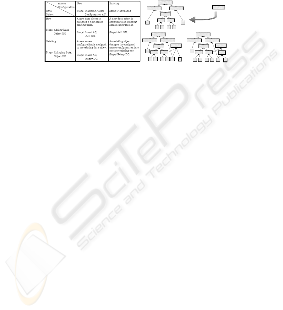
possible scenarios of access control policy update. According to the nature of the in-
troduced update, we apply a combination of three basic steps as presented in the table.
Below we describe these basic steps and their effects on the database.
An existing object
c
hanges the assigned
a
ccess configuration into
a
nother existing one
Steps: Rekey DO.
A new access
c
onfiguration is assigned
t
o an existing data object
Steps: Insert AC,
Rekey DO.
Existing
Steps: Rekeying Data
O
bject DO
A new data object is
a
ssigned to an existing
a
ccess configuration
Steps: Add DO.
A new data object is
a
ssigned a new access
c
onfiguration
Steps: Insert AC,
A
dd DO.
New
Steps: Adding Data
O
bject DO
Existing
Steps: Not needed
New
Steps: Inserting Access
C
onfiguration AC
Access
C
onfiguration
Data
Object
A,B,C,D,E,F
A,C,D,E,F B,C,D,E,F
C,D,E,F
C D E F
A B
C,D E,F
B,E,F,G
A,B,C,D,E,F
A,C,D,E,F B,C,D,E,F
C,D,E,F
C D E F
A
B
C,D E,F
B,E,F,G
G
A,B,C,D,E,F
A,C,D,E,F B,C,D,E,F
C,D,E,F
C D E F
A
B
C,D E,F
B,E,F,G
G
B,G
Access configuration
joins the hierarchy
(1) (2)
Fig.3. Update scenarios and example.
The Insert Access Configuration (Insert AC) step is needed when new access con-
trol policies imply a new access configuration AC
new
, which is not an element of the
current hierarchy (represented by an access control graph). This is the only step, in
which the hierarchy must be updated. We proceed as follows. The new node is cre-
ated in the hierarchy for AC
new
. It is not assigned any children. If it were, then the set
{X ∈ G : ∃
Z∈G
AC
new
։ Z and X ։ X} must be assigned new keys. This could
require the re-encryption of the whole hierarchy. Thus, to insert AC
new
, we apply the
operations G.InsertCoverM in(AC
new
) and G.CreateT ree(AC
new
) (see Section
3.1). After these two steps conditions [a-d] from Section Table 1 remain satisfied and
we can generate new keys for new nodes using the DH scheme. No rekeying is required
whatsoever. Frequent updates of the hierarchy influence the performance and public
space. Therefore after a certain number of updates the whole hierarchy is rebuilt and
rekeyed. If the access configuration in the hierarchy does not correspond to any data
object, it is not removed until the hierarchy is rebuilt, and remains as a virtual node.
Applying updates to an example hierarchy is shown in Figure 3.
The Add Data Object (Add DO) step is required when a new data object is assigned
an existing access configuration. In this case, a new secret key for the new data object
is created, the object is encrypted with the new key, and the new key is encrypted with
the key of the (existing) access configuration assigned to the object.
The Rekey Data Object (Rekey DO) step is performed, when an access configura-
tion AC
old
assigned before to a data object d ∈ D is changed into another existing
access configuration AC
new
. Assume K(d) is the data encryption key assigned to d,
K(AC
new
) and K(AC
old
) are the key encryption keys corresponding to these access
configurations. There are two possible cases:
1. AC
old
⊂ AC
new
: in this case the users gain access rights and K(d) is re-encrypted
with K(AC
new
)
2. otherwise: in this case the users loose rights and K(d) must be changed into K
new
(d),
d is re-encrypted with K
new
(d), K
new
(d) is encrypted with K(AC
new
) and stored.
15

5 Discussion
In this section, we compare our scheme to the schemes described in Section 2. Com-
pared to broadcast encryption methods, the solution we propose eliminates the need for
multiple copies of data keys and reduces to a single key the storage required per user.
Therefore, we focus in this section on the comparison of our scheme with the key gen-
eration schemes. For the sake of a clear comparison we divide them into two groups:
PKC (Public Key Cryptography) based schemes and SKC (Symmetric Key Cryptogra-
phy) based schemes.
Let n be the size of a partial order to which a PKC scheme is applied. The PKC
based solutions are essentially extensions of two basic approaches. The first approach
requires storing large public keys proportional to the product of first n primes: p
1
·· · ··p
n
[1,8,9]. The upper bound for the product of n primes is (n log n)
n
, so the size in bits
required to store it is log(n log n)
n
= n log(n log n). Each key derivation step requires
a single operation, but computation on numbers of that size implies the time needed for
the key derivation proportional to n. In the second approach, the number of modular
exponentiations needed for computing the private keys is proportional to n [2,10, 11].
This is applicable for reasonably small partial orders, for instance hierarchies inside
a company or an institute. However in our settings, assuming that N is the number of
users, the number n of possible access configurations can reach 2
N
. Therefore the direct
application of these schemes for partial order on access configurations results in a key
derivation time that is exponential in N .
In the scheme we propose, all the private and public keys are bounded from above
by a large prime number p. To ensure that the keys are unique, p must be of order n
α
for
some constant α. Therefore the size of a public key is bounded from above by α log n. It
is in the worst case proportional to N . The key derivation time in the proposed scheme
is proportional to the height of the partial order. Since the height of a partial order on
access configurations cannot exceed N, the derivation time is bounded from above by
N. An additional advantage of our scheme is the support for flexible updates, which are
poorly supported in the PKC based schemes.
The SKC based schemes [2, 12, 13, 3] are more efficient, however some successful
attacks against them have been proposed [14]. Furthermore, we argue below that in
terms of storage space our scheme is more efficient than any of these schemes applied
directly to an inclusion partial order on access configurations.
Essentially, the SKC based schemes assign the private keys to the nodes and public
keys to the edges of the given partial order. When the nodes are access configurations,
this order is naturally given by set inclusion. It is represented by a directed graph with n
nodes (access configurations) and e edges. An SKC based scheme assigns O(n) private
and O(e) public keys. As emphasized in the problem statement given in Section 2,
inclusion order gives many redundant edges, which in turn give many redundant public
parameters. Intuitively, our partial order construction aims at minimizing the number of
edges.
A perceptive reader spots immediately that our scheme assigns both private and
public keys to the nodes of the partial order we construct. However, for each node AC
except for N singletons {u} we have |In(AC)| = 2 (V -condition). Therefore, the
16
number of nodes is equal to
|edges|
2
+ N, and this is the number of public keys issued
by our scheme
4
.
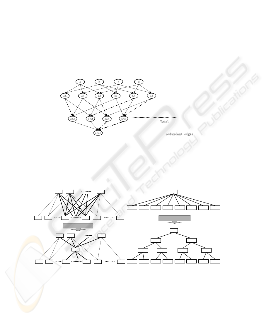
This does not complete the analysis, because the number of edges in the order we
construct is different than in the inclusion order. Let n and e be the number of nodes
and edges in the inclusion order given on access configurations {u}
u∈U
and AC(d)
d∈D
.
Let n
′
t
and e
′
t
be the number of nodes and edges in our construction after the t th phase
of the algorithm. After the first phase, the following conditions are satisfied: e
′
1
≤ e
and n
′
1
= n. This is due to the weaker order conditions defined in Section 2. When
constructing the order, we insert only necessary edges that connect users with access
configurations they belong to, thus for many inclusions AC
1
⊂ AC
2
there is no relation
(edge) in the constructed order. An example is shown in Figure 4.
dcba
cdbdbcadacab
bcdacdabdabc
abcd
4
3
4
1
¸
¸
¹
·
¨
¨
©
§
x
redundant edges
2
4
4
2
¸
¸
¹
·
¨
¨
©
§
x
redundant edges
i-1 th level
i th level
¸
¸
¹
·
¨
¨
©
§
x
i
n
i 2
redundant
edges
T
otal:
redundant edges
¦
¸
¸
¹
·
¨
¨
©
§
x
n
i
i
n
i
3
2
Fig.4. Full access control hierarchy.
After the second phase, the number of edges decreases even more: e
′
2
≤ e
′
1
. Each
inserted dummy access configuration D decreases |In(AC
i
)| by α ≥ 2 configurations.
The precise number of edges after inserting D changes from e
′
1
to e
′
1
−(α−1)·|In(D)|+
α as shown in Figure 5a.
AC
1
AC
2
AC
a
AC’
1
AC’
2
AC’
m- a
AC’
m- a_ 1
AC’
m
AC’
a
AC
1
AC
2
AC
a
AC’
1
AC’
2
AC’
m- a
AC’
m- a_ 1
AC’
m
AC’
a
D
( a)
AC
I n( AC)
2
CreateTree( AC)
I n( AC)
1
I n( AC)
3
I n( AC)
4
I n( AC)
5
I n( AC)
6
I n( AC)
7
I n( AC)
8
AC
I n( AC)
2
I n( AC)
1
I n( AC)
3
I n( AC)
4
I n( AC)
5
I n( AC)
6
I n( AC)
7
I n( AC)
8
D
1
D
2
D
3
D
4
D
5
D
6
( b)
Fig.5. Insertion of a dummy access configuration D and tree transformation.
After the third phase, e
′
3
≤ 2e
′
2
− 1, so the number of edges at most doubles. This is
due to the transformations made by function CreateT ree(AC), which transforms AC
4
|X| denotes the number of elements of set X
17

with In(AC) into a binary tree with AC as a root and In(AC) as leaves (see Figure 5
b). Each call of CreateT ree(AC) adds |In(AC)| − 1 edges.
Thus, in the end we have e ≥ e
′
1
≥ e
′
2
≥
e
′
3
2
and n
′
3
=
e
′
3
2
+ N is the number of
public parameters in our scheme. This in practice means that in the worst case, when
all the reductions of edges do not bring any result, we use at most (e + N) public
parameters, whereas SKC based schemes use at least e. However, when dealing with
a few or many intersecting access configurations we expect an improvement, as shown
in the figures. The number of private parameters remains the same for both SKC based
schemes and our scheme and is equal to n = n
′
1
, since we do not have to store the
private keys for dummy access configurations. Concluding this comparison, it is worth
mentioning that the security of our scheme is guaranteed by the security of well-known
DH key-exchange protocol.
6 Conclusions
In this paper, we proposed an efficient method to design a partial order on access con-
figurations. We provided a scheme to assign and derive secret keys for the proposed
partial order.
Compared to broadcast encryption methods, our solution eliminates the need for
multiple copies of data keys and reduces to a single key the storage required per user.
This improvement is achieved by applying the proposed key generation scheme. Com-
pared to key generation schemes adapted for access control purposes, our solution re-
duces the required size of public information. This is achieved thanks to the special
properties of the hierarchy we propose, designed especially for the access control pur-
pose. To the best of our knowledge, and as reported in [15], nobody has yet proposed
a key generation solution that takes advantage of constructing the hierarchy especially
for the access control settings.
Finally, since access control systems are very dynamic, the issue of changing ac-
cess rights cannot be neglected. Our solution supports flexible updates of access rights
granted to the users.
References
1. Akl, S.G., Taylor, P.D.: Cryptographic solution to a problem of access control in a hierarchy.
ACM Trans. Comput. Syst. 1 (1983) 239–248
2. Harn, L., Lin, H.Y.: A cryptographic key generation scheme for multilevel data security.
Comput. Secur. 9 (1990) 539–546
3. Lin, C.H.: Dynamic key management schemes for access control in a hierarchy. Computer
Communications 20 (15 December 1997) 1381–1385(5)
4. Fiat, A., Naor, M.: Broadcast encryption. In: CRYPTO ’93: Proceedings of the 13th an-
nual international cryptology conference on Advances in cryptology, New York, NY, USA,
Springer-Verlag New York, Inc. (1994) 480–491
5. Naor, D., Naor, M., Lotspiech, J.B.: Revocation and tracing schemes for stateless receivers.
In: CRYPTO ’01: Proceedings of the 21st Annual International Cryptology Conference on
Advances in Cryptology, London, UK, Springer-Verlag (2001) 41–62
18

6. Asano, T.: A revocation scheme with minimal storage at receivers. In: ASIACRYPT ’02:
Proceedings of the 8th International Conference on the Theory and Application of Cryptol-
ogy and Information Security, London, UK, Springer-Verlag (2002) 433–450
7. Bertino, E., Carminati, B., Ferrari, E.: A temporal key management scheme for secure broad-
casting of xml documents. In: CCS ’02: Proceedings of the 9th ACM conference on Com-
puter and communications security, New York, NY, USA, ACM Press (2002) 31–40
8. TS Chen, Y.C.: Hierarchical access control based on chinese remainder theorem and sym-
metric algorithm. Computers & Security 21 (2002) 565–570
9. Kuo, F.H., Shen, V.R.L., Chen, T.S., Lai, F.: Cryptographic key assignment scheme for
dynamic access control in a user hierarchy. Volume 146., Dept. of Electr. Eng., Nat. Taiwan
Univ., Taipei, IEE (September 1999) 235 – 240
10. Hwang, M.S., Yang, W.P.: Controlling access in large partially ordered hierarchies using
cryptographic keys. J. Syst. Softw. 67 (2003) 99–107
11. Lin, I.C., Hwang, M.S., Chang, C.C.: A new key assignment scheme for enforcing compli-
cated access control policies in hierarchy. Future Gener. Comput. Syst. 19 (2003) 457–462
12. Chien, H-Y; Jan, J.K.: New hierarchical assignment without public key cryptography. Com-
puters & Security 22 (2003) 523–526
13. Lin, C.H.: Hierarchical key assignment without public-key cryptography. Computers &
Security 20 (2001) 612–619
14. Lee, N.Y., Hwang, T.: Comments on dynamic key management schemes for access control
in a hierarchy’. Computer Communications 22 (1999) 87–89
15. Crampton, J., Martin, K., Wild, P.: On key assignment for hierarchical access control. In:
CSFW ’06: Proceedings of the 19th IEEE Workshop on Computer Security Foundations,
Washington, DC, USA, IEEE Computer Society (2006) 98–111
A Appendix: The Algorithm
The output of the CreateHierarchy(Access Table ACCESS) algorithm is the directed
graph G = (V, E(V )) in a V-form, where the node set V ⊇ {AC(d)|d ∈ D}. The
algorithm uses an abstract data structure Digraph G to represent the order on access
configurations it constructs. The standard available operations are: New(), Cover(Node
A), InsertNode(Node A), InsertEdge(Node A, Node B), RemoveNode(Node A) and Re-
moveEdge(Node A, Node B). We assume that the graph does not allow duplicate nodes
(if the node to be inserted already exists, than the insertion procedure terminates). Sim-
ilarly, no multiple arcs are allowed between two nodes. The algorithm CreateHierar-
chy(Access Table ACCESS) uses the priority queue Q. A priority queue is an abstract
data type to efficiently support finding the item with the highest priority across a series
of operations. The basic operations are: New(), Insert(Item, Priority), ExtractMax(),
ExtractMin(), FindMax(), FindMin() and Remove(Item). The items of Q are the access
configurations. The algorithm calls two additional procedures: InsertCoverMin(Node
AC) and CreateTree(Node AC), which are presented in Section A.1. The number of el-
ements in data structure X is denoted as #X. For data structures X and Y we denote
their set difference (the elements in X but not in Y ) as X − Y , and their intersection as
X ∗ Y .
A.1 Subprocedures Codes
algorithm InsertCoveredMin(Node AC)
19

begin
(1) G.InsertNode(AC);
(2) Node X:=AC;
(3) while (#X > 0) do
begin
(4) Node Y := maximal Z in G, s.t. X contains Z;
(5) G.InsertEdge(Y,X);
(6) X:=X - Y;
end
end.
algorithm CreateTree(Node AC)
begin
(1) pos:=0;
(2) for each (X in G s.t. X ->> AC) do
begin
Q.Insert(X,pos++);
(3) while (#Q > 2) do
begin
(4) AC_1:=Q.ExtractMin(); AC_2:=Q.ExtractMin();
(5) Node Y:=AC_1 + AC_2; (6) G.InsertNode(Y);
(7) G.InsertEdge(AC_1,Y); G.InsertEdge(AC_2,Y);
(8) G.RemoveEdge(AC_1,AC); G.RemoveEdge(AC_2,AC);
(9) G.InsertEdge(Y,AC); (10) Q.Insert(Y,position++);
end
end
end.
A.2 The Main Code
algorithm CreateHierarchy(Access Table ACCESS)
begin
(1) Digraph G := New(); PriorityQueue Q := New();
(2) for each (u in U) do G.InsertNode({u});
(3) for each (d in D) do Q.Insert(AC(d),#AC(d));
(4) while (Q.size() > 0) do
begin
(5) AC:=Q.ExtractMin();
(6) G.InsertCoveredMin(AC);
end
(7) for each (AC in G s.t. #In(AC) > 2) do Q.Insert(AC,#In(AC));
(8) repeat
(9) Node AC:=Q.FindMax(); MAX_CUT := empty set;
(10) for each (AC_k in Q) do
begin
(11) CUT:=AC
*
AC_k;
(12) if ( #{X in G s.t. X ->> AC, CUT contains X }
> #{ X in G s.t. X ->> AC, MAX_CUT contains X}
AND
there are X,Y in G
s.t. X != Y, X,Y ->> AC, CUT contains X
*
Y
AND
there are X,Y in G
s.t. X != Y, X,Y ->> AC_k, CUT contains X
*
Y
(13) then MAX_CUT := CUT;
end // for each
(14) if (MAX_CUT not empty) (15) then // if MAX_CUT found
20

begin
(16) G.InsertCoveredMin(MAX_CUT);
(17) for each (X in Q) do
begin
(18) if (X contains strictly MAX_CUT
AND
there are Y,Z in G s.t. Y != Z,
Y,Z ->> X, MAX_CUT contains X
*
Z)
(19) then
begin
(20) G.InsertEdge(MAX_CUT,X);
(21) for each (Y in G s.t. Y ->> X, MAX_CUT contains Y) do
G.RemoveEdge(Y,X);
(22) if (#In(X) <= 2) then Q.Remove(X) ,
end // if
end //for each
(23) if (#In(MAX_CUT) > 2)
(24) then Q.Insert(MAX_CUT,#In(MAX_CUT));
end // if
(25) else G.CreateTree(AC); Q.Remove(AC);
(26) until Q is empty; // repeat
end.
B Appendix: Correctness Proof
Lemma 1 After the termination of the algorithm CreateHierarchy, the output graph
G = (V, E(V )) satisfies the following five conditions:
(a) ∀
u∈U
{u} ∈ V
(a’) ∀
d∈D
AC(d) ∈ V
(b) u ∈ AC ⇒ {u} ։ AC
(b’) AC
1
։ AC
2
⇒ AC
1
⊆ AC
2
(c) ∀
AC∈V
|In(AC)| = 0 or |In(AC)| = 2
(d) ∀
AC
1
,AC
2
∈V
|{AC ∈ V : AC −→ AC
1
, AC −→ AC
2
}| ≤ 1
Proof. In the first phase (1-6), the algorithm constructs the hierarchy, which satisfies
(a), (a’), (b) and (b’). Since the arcs are added only between such two configurations,
that one contains the other, (b’) remains trivially satisfied until the termination. After
addition of singletons (2) G satisfies (a), and after addition of existing access configu-
rations (3-6), G satisfies (a’) as well. Both (a) and (a’) are not affected by the algorithm
anymore and remain satisfied until termination. After line (2) G satisfies (b) trivially
because V is the set of singletons. (b) remains satisfied after each step of the main algo-
rithm until line (21), because the procedures InsertCoveredMin and CreateTree preserve
(b), and only in line (21) the edges are removed so (b) has a chance to be affected.
In the second phase, from line (7), additional access configurations are inserted to
reduce the number of edges and satisfy the condition (c). Beginning at line (7) until the
termination, Q stores the nodes AC ∈ V for which |In(AC)| > 2 and thus they still
need to be processed. The priorities of the items on Q determine the order of process-
ing the nodes of G. The priority of an item AC is |In(AC)|. The nodes with larger
In(AC) are processed first. The main loop REPEAT (8-26) is terminated when Q is
empty, so all the nodes have at most two incoming edges. In (9) node AC, with the
maximal number of incoming edges, is extracted from Q to reduce |In(AC)|. After
21

current iteration of the main loop, the size |In(AC)| is reduced, and therefore each it-
eration reduces the number of incoming edges of a node, with the maximal number of
incoming edges in G. Thus, at some point the maximal number of incoming edges in G
must reach 2. This guarantees that the loop terminates. In lines (10-13), the algorithm
searches for the dummy access configuration M AX
CU T , which insertion reduces
|In(AC)| maximally, under the assumption that it also reduces |In(AC
k
)| for some
other access configuration AC
k
still stored on Q. If (14) MAX CU T was found, then
(15) it is inserted into G (16), and for each node X on Q (17) the algorithm checks
(18) whether |In(X)| can be reduced using M AX
CU T . If the condition from line
(18) is satisfied, then MAX CU T −→ X is added to |In(X)| (20), but then based
on (18) at least two edges in In(X) are removed in (21), and therefore |In(X)| de-
creases at least by one. AC satisfies (18), thus one of the iterations of loop for each
(17-24) reduces In(AC) for a node AC with the maximal number of incoming edges
in G. In(MAX
CU T ) does not increase back the maximal number of incoming edges
in G, because |In(M AX CUT )| < |In(AC)|. Based on (18), (b) is preserved after
each execution of line (21). In (23) the algorithm enqueues MAX
CU T if it needs to
be processed. If (25) M AX CUT was not found, then |In(AC)| is reduced to 2 by
inserting to G a binary tree rooted in AC with configurations X : X −→ AC as leaves.
The result of the algorithm is the V-graph satisfying (a-d).
22
