
Comparison of IPsec to TLS and SRTP for
Securing VoIP
Barry Sweeney and Duminda Wijesekera
Science Applications International Corporation, 1710 SAIC Drive, McLean, VA 20194, USA
George Mason University, 4400 University Drive, Fairfax, VA, 22030, USA
Abstract. With the IETF requirement to include Internet Protocol Security
(IPsec) in every implementation of Internet Protocol version 6 (IPv6), it is
prudent to consider IPsec as a viable protocol for securing IPv6 Voice over
Internet Protocol (VoIP) sessions. This approach is currently inconsistent with
the direction of industry, which has chosen Transport Layer Security (TLS) to
secure the Session Initiation Protocol (SIP) packets and Secure Real-time
Transport Protocol (SRTP) to secure the Real-time Transport Protocol (RTP)
packets for VoIP sessions. A comparison of these two approaches is currently
not available and this paper attempts to provide that comparison and discuss the
advantages and disadvantages of each approach so that implementers and
Information Assurance (IA) architects may make an informed decision. This
paper is not necessarily an IA document, but is instead focused on the
comparison of the two approaches based on many factors to include IA
concerns.
1 Introduction
With the emergence of IP as the dominant telecommunications technology for the
future, telephony vendors are investing heavily in Voice Over IP (VoIP) technologies,
often at the expense of their legacy Time Division Multiplexing (TDM) platforms. As
the investments and functionality of VoIP technologies continue to expand, it is likely
that investment in Signaling System #7 (SS7) and Integrated Services Digital
Networks (ISDN) will decrease. A key concern for voice system vendors and
customers is that IP has a significantly different security posture than traditional TDM
voice systems and therefore VoIP may be more vulnerable to attack than TDM voice
systems. For instance, TDM voice systems are typically stovepipe systems that are
developed using vendor proprietary operating systems and source code and are
deployed in non-converged environments where it is difficult for external users to
gain access. In comparison, VoIP systems typically use LINUX or Windows
operating systems and are deployed on converged IP networks that are attached to the
Internet. Due to this paradigm shift, it becomes necessary to secure the VoIP
associated packets to include the signaling and bearer streams. For instance, the
bearer packets should be secured to ensure that a malicious user is prevented from
capturing, listening, and playing back a voice conversation that may contain personal
information like stock transactions or credit card information.
With the Internet Engineering Task Force (IETF) requirement to include Internet
Protocol Security (IPsec) in every implementation of Internet Protocol version 6
(IPv6), it is prudent to consider IPsec as a viable protocol for securing IPv6 VoIP
sessions. This approach is currently inconsistent with the direction of industry, which
Sweeney B. and Wijesekera D. (2007).
Comparison of IPsec to TLS and SRTP for Securing VoIP.
In Proceedings of the 5th International Workshop on Security in Information Systems, pages 82-92
DOI: 10.5220/0002433500820092
Copyright
c
SciTePress
has chosen Transport Layer Security (TLS) to secure the Session Initiation Protocol
(SIP) packets and Secure Real-time Transport Protocol (SRTP) to secure the Real-
time Transport Protocol (RTP) packets for VoIP sessions. A comparison of these two
approaches is currently not available and this paper attempts to provide that
comparison and discuss the advantages and disadvantages of each approach so that
implementers and Information Assurance (IA) architects may make an informed
decision. SIP is becoming the dominant signaling protocol used to establish VoIP
sessions. RTP is the dominant protocol used to packetize voice conversations for IP
transport between two phones. TLS, SRTP, and IPsec are protocols that are used to
secure SIP and RTP sessions in order to provide authentication, integrity, and
confidentiality for the VoIP associated IP packets. This paper is not necessarily an IA
document, but is instead focused on the comparison of the two approaches based on
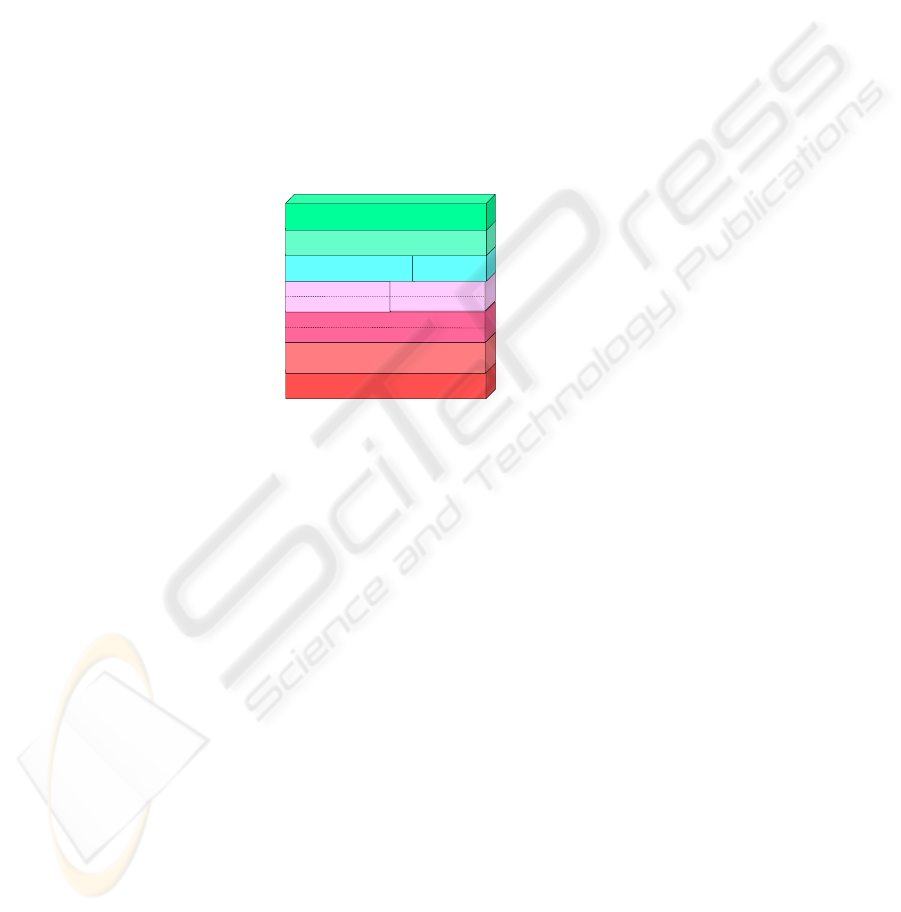
many factors to include IA concerns. Figure 1 shows the relationship of TLS, IPsec,
SRTP, SIP, and RTP and where they fit within the Open Systems Interconnections
(OSI) model. Figure 2 shows the basic SIP and RTP call flow. IPsec, TLS, and SRTP
would be used to secure the basic SIP and RTP call flow.
100BT, RS-530, Token Ring, Etc.
ATM, Ethernet, Frame Relay, HDLC, Etc.
IPsec
IP
Physical Layer
Link Layer
Network Layer
Transport Layer
TLS
TCP
SRTP
UDP
SIP RTP
Session Layer
Presentation Layer
Application Layer
Fig. 1. VoIP and the OSI Model.
As mentioned earlier, the IETF requires in Request For Comment (RFC) 2460,
“Internet Protocol, Version 6 (IPv6) Specification” that every IPv6 implementation
include IPsec as described in RFC 2401 and its associated RFCs. RFC 2460 does not
mandate that IPsec is used, but does require its implementation. For instance, if the
vendor showed the capability to send an IPv6 packet using IPsec, then there is no
requirement for them to actually use IPsec to secure any application’s packet to claim
IPv6 compliance. Various Government [8] and industry communities are migrating to
IPv6 and would like to take advantage of its embedded security features, to include
IPsec, for all IP sessions. However, many VoIP vendors have not found a commercial
driver for migrating to IPv6 and are developing their solutions based on IPv4 and
protocols they consider more suited for their VoIP solutions (SIP and RTP). Many
vendors have also decoupled IPsec and IPv6 from a technical and marketing
perspective and do not feel that IPsec is necessary to claim an IPv6 capability for their
solution. In addition, many vendors feel that IPsec is not a viable approach for
securing the signaling and bearer session due to reasons stated in this paper. As a
result the VoIP industry is developing solutions that cannot easily migrate to IPsec
and will not be able to take advantage of its integration within IPv6.
83
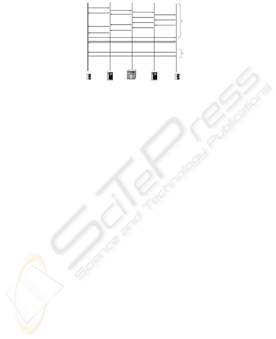
SIP Client
SIP ClientLocal Call Controller Local Call ControllerSoftswitch
SIP INVITE
SIP INVITE
SIP INVITE
SIP INVITE
100 TRYING
100 TRYING
100 TRYING
180 RINGING
180 RINGING
180 RINGING
180 RINGING
200 OK
200 OK
200 OK
200 OK
ACK
RTP Session (One Way)
RTP Session (One Way)
OK
BYE
SIP
SIP
Fig. 2. Basic VoIP Message Flow.
2 Protocol Overview
Session Initiation Protocol (SIP)
The Session Initiation Protocol (SIP) is described in RFC 3261 as an application-layer
control (signaling) protocol for creating, modifying, and terminating sessions with
one or more participants. VoIP vendors have and are currently investing heavily in
SIP for VoIP signaling. The diagram in Figure 2 shows the basic message flow
associated with establishing a SIP voice session. The SIP session establishment is
initiated using a SIP INVITE message that is used to negotiate the type of media
session (i.e., CODEC, silence suppression, security requirements, etc.) for the
originating and terminating SIP client. The INVITE message is followed by a 100
TRYING message, which provides status to the previous SIP hop in the message
flow. Upon a call authorization by the terminating Local Call Controller (LCC) and
SIP client, a 180 RINGING message is sent to convey that the terminating SIP client
phone is ringing. Once the handset is taken off-hook, a 200 OK message is conveyed
to inform the SIP clients that the call has been answered. Then, RTP is used to
packetize the voice conversation into IP for transmission over the IP network. Upon
placing a handset on-hook, the call is terminated by a SIP client using the BYE
message, which is acknowledged by the OK message.
Real-Time Transport Protocol (RTP)
The Real-Time Transport Protocol (RTP) is described in RFC 3550 as a protocol that
provides end-to-end network transport functions suitable for applications transmitting
real-time data, such as audio over multicast or unicast network services. It is currently
the only viable protocol for VoIP bearer streams. The RTP session by each SIP client
is initiated upon receipt of the ACK or OK message as shown in Figure 2.
Internet Protocol Security (IPsec)
Internet Protocol Security (IPsec) is described in RFC 2401 and 4301 as a set of
security services at the IP layer that enables a system to select required security
protocols, determine the algorithm(s) to use for the service(s), and put in place any
cryptographic keys required to provide the requested services. RFC 4301 obsoletes
RFC 2401 and for the rest of this document, references to IPsec imply RFC 4301
84

unless specifically stated. The IPsec security association is established prior to the
initiation of the SIP and RTP sessions, and once established IPsec would be used to
secure the SIP and RTP packets as they transit the network layer of the OSI model
within the appliance’s IP stack.
Transport Layer Security (TLS)
Transport Layer Security (TLS) is described in RFC 4346 as a protocol that provides
communications security over the Internet. The protocol allows client/server
applications to communicate in a way that is designed to prevent eavesdropping,
tampering, and/or message forgery. RFC 4346 obsoletes RFC 2246 and for the rest of
this document, references to TLS imply RFC 4346 unless specifically stated. TLS
version 1.0 is also known as Secure Socket Layer (SSL) version 3.1. The TLS
security association is established prior to the initiation of the SIP session. TLS is
used to secure the SIP packets as they transit the transport layer of the OSI model
within the appliance’s IP stack.
Secure Real-time Transport Protocol (SRTP)
The Secure Real-time Transport Protocol (SRTP) is described in RFC 3711 as a
profile of the Real-time Transport Protocol (RTP), which can provide confidentiality,
message authentication, and replay protection to the RTP traffic and to the control
traffic for RTP using the Real-time Transport Control Protocol (RTCP). The basic
message flow for SRTP with SIP is the same as shown in Figure 2. SRTP is used to
secure the RTP packets as they transit the transport layer of the OSI model within the
appliance’s IP stack and relies on the SIP messages to convey the keying material and
for TLS to provide authentication of the SIP clients through the transitive trust model.
3 Comparison Categories
This paper provides a comparison between IPsec and TLS/SRTP for securing SIP and
RTP streams. For each comparison category a discussion is provided on the
advantages and disadvantages associated with each alternative.
As a competitor, the International Telecommunications Union (ITU) H.323
standard is also used for legacy VoIP and video over IP signaling sessions, but IPsec
is the preferred security protocol for H.323 and no comparison of IPsec and TLS is
required for H.323 [4].
Implementation & IETF Support
From a SIP perspective TLS is simpler to integrate with SIP than IPsec. RFC 4346
associates 200 requirements with a TLS implementation. In contrast, IPsec has over
500 requirements that govern the implementation of IPsec and are found in
approximately 11 RFCs.
The IETF has published several documents on how SIP, TLS, and SRTP could be
integrated. In addition, the Department of Defense (DoD) has developed an
interoperable requirements specification for the securing of SIP with TLS and the
integration of SIP/TLS with SRTP. The authors are unaware of any IETF published
documents that describe how IPsec and SIP or RTP could be integrated and it is
currently not well understood by industry. However, some research oriented
implementations have occurred and generally show that it is more difficult to
85
implement due to its requirement to access the kernel of the operating system [1, 6].
VoIP vendors typically overlay their VoIP applications on existing operating systems
such as Windows, Linux, or UNIX and typically have limited access or do not have
access to the operating system kernel.
The implementation of both approaches on a VoIP appliance (i.e., end instrument
(phone), Local Call Controller (LCC), etc.) may not be feasible depending on the
vendor and the type of appliance. For example, some end instruments (EI) have
limited memory, storage and processing capabilities and could not support the
simultaneous implementation of TLS, SRTP, and IPsec.
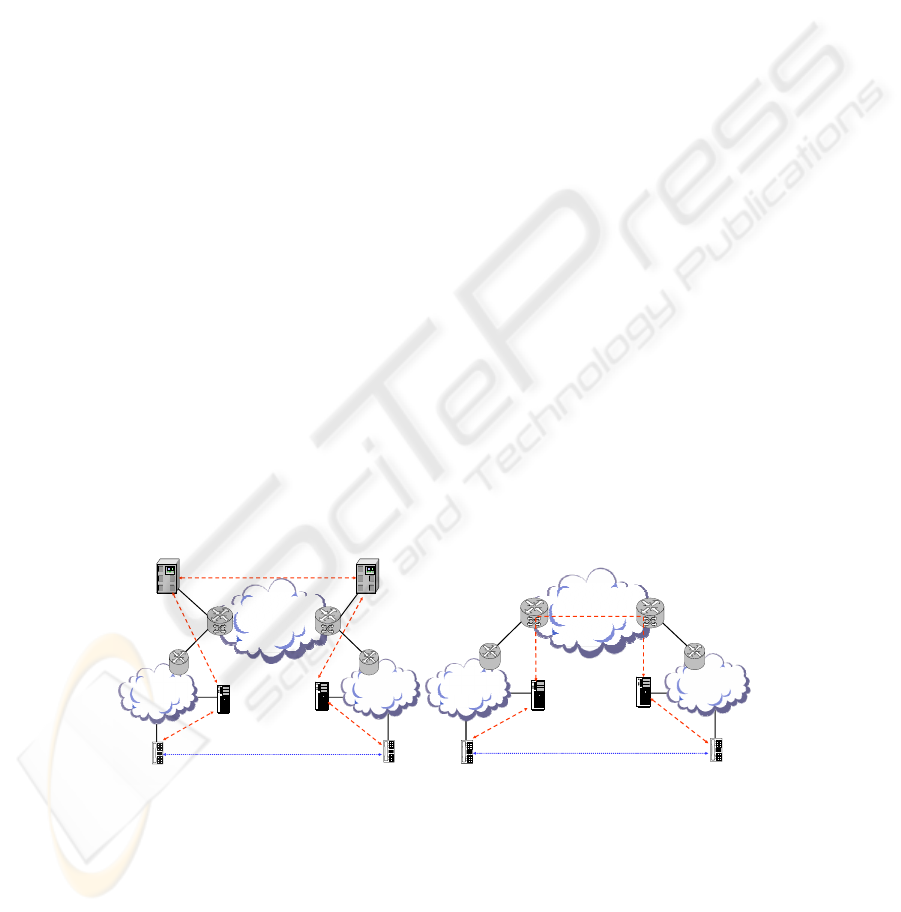
Support for Hierarchical Signaling
The primary marketing feature of IPsec is that it provides end-to-end security, which
is preferred for most data applications. However, commercial voice offerings are
based on a hierarchical signaling model where an EI signals to a LCC to establish a
session using a proprietary signaling protocol. The LCC typically signals the
provider’s Softswitch (SS) using SIP for off-enclave sessions and the SS may signal
to another SS or LCC in order to complete the session to the remote EI as shown in
Figure 3. A proprietary signaling protocol is used between the EI and the LCC to
allow the vendor to provide vendor unique value added user features, which is not
achievable if a standardized protocol were adopted.
Within the hierarchical model, each hop in the hierarchy must be able to decrypt
the signaling packet, process the packet, and reencrypt the signaling packet prior to
forwarding the packet. This hierarchical model prohibits the use of an end-to-end
model for signaling. Both IPsec and TLS could be implemented to support a hop-by-
hop security model for the signaling packets. However, the VoIP vendors currently
feel that TLS is better suited for this model and are implementing TLS and have not
invested in IPsec.
The end-to-end security model is achieved for the bearer path and can be
implemented using either SRTP or IPsec. The IETF has published an approach for
distributing the SRTP keying material within the SIP signaling packets so that a
session can be established upon the completion of the signaling. A similar approach
could be developed for IPsec, but is not currently available.
RTP with
IPsec or SRTP
P
r
o
p
r
i
e
t
a
r
y
S
i
g
n
a
l
i
n
g
P
r
o
p
r
i
e
t
a
r
y
S
i
g
n
a
l
i
n
g
SI
P
w
i
t
h
T
L
S
o
r
I
Ps
e
c
SIP with TLS or IPsec
S
I
P
w
i
t
h
T
L
S
o
r
I
P
s
e
c
WAN
LAN
LAN
Hierarchical Model
Softswitch
Local Call
Controller
Provider Edge
Router
Customer
Edge Router
Customer
Edge Router
Provider Edge
Router
Softswitch
Local Call
Controller
RTP with
IPsec or SRTP
P
r
o
p
r
i
e
t
a
r
y
S
i
g
n
a
l
i
n
g
P
r
o
p
r
i
e
t
a
r
y
S
i
g
n
a
l
i
n
g
SIP with
TLS or IPsec
WAN
LAN
LAN
End-to-End Model
Local Call
Controller
Local Call
Controller
CER
Customer Edge
Router
Provider Edge
Router
Provider Edge
Router
Fig. 3. Hierarchical Model vs. End-to-End Model.
Packet Size Efficiency
The comparison of packet size efficiency is primarily applicable to the bearer stream
packets because the number of signaling packets in relation to bearer packets makes
86
the bandwidth impact of the signaling stream negligible. In comparing the bearer
packet sizes, it is difficult to compare IPsec to SRTP because it depends on whether
transport mode, tunnel mode, padding, integrity, and/or authentication are
implemented or used. However, assuming that IPsec Encapsulating Security Protocol
(ESP) in transport mode is used with a minimum of padding and a modest integrity
check value (ICV), then it is fair to claim that SRTP is six percent more efficient than
IPsec for IPv6 packets. If IP header integrity is required, the IPsec Authentication
Header (AH) could also be used and additional overhead would be incurred.
Using the same assumptions for SIP, IPsec requires two additional bytes in
comparison to TLS for securing SIP messages. One factor that was not evaluated was
the impact of RTP header compression. In environments where RTP header
compression is implemented, SRTP is up to 10 additional bytes more efficient than
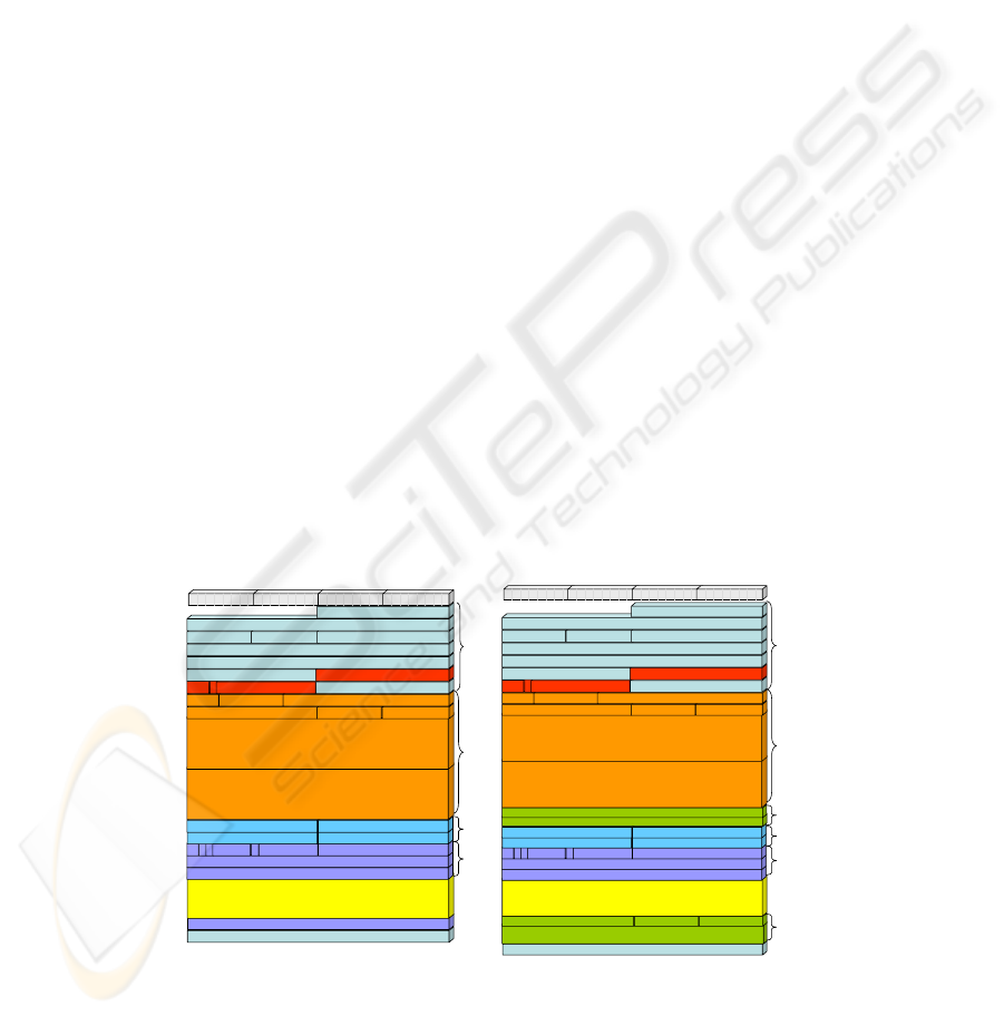
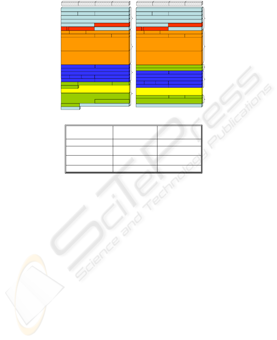
IPsec because the integrity check in IPsec incorporates the RTP header. Figure 4
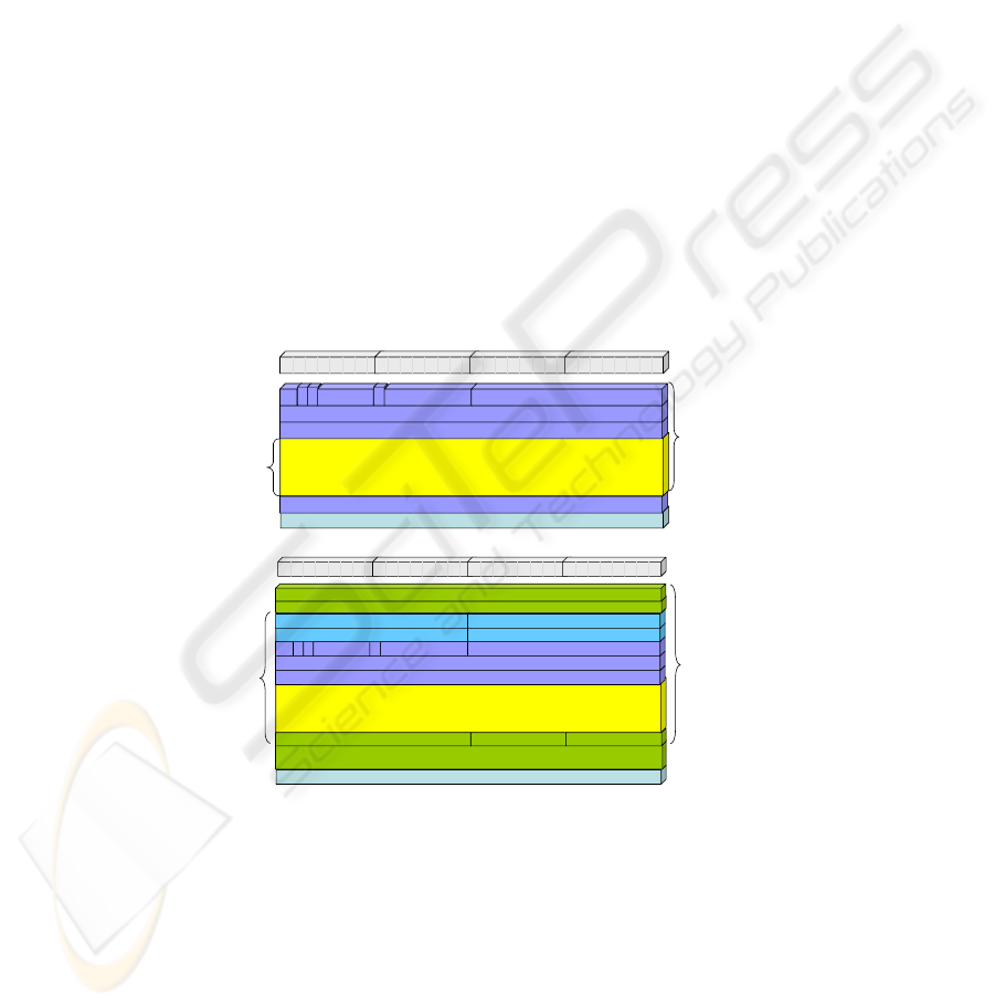
shows the IPv6 packet formats for RTP with SRTP and IPsec. Figure 5 shows the
IPv6 packet formats for SIP with TLS and IPsec. Figure 6 summarizes the results of
the packet size comparison. The bandwidth associated with SIP in Figure 6 is listed as
not applicable because the SIP sessions bandwidth implications are considered
minimal and the flows are not continuous in comparison to the bearer streams.
Commercial Acceptance
Commercial VoIP vendors are investing heavily in the use of TLS and SRTP to
secure VoIP sessions. IPsec was considered by the SIP VoIP vendors, but TLS and
SRTP were deemed a better solution. At this time no commercial implementation of
IPsec exists to secure SIP-based VoIP sessions (to include the bearer stream) whereas
several vendors are fielding VoIP solutions that secure SIP with TLS and RTP with
SRTP. Vendors that have chosen to use legacy H.323 signaling for their voice
solutions will likely choose to secure their solutions with IPsec. However, most H.323
vendors are currently using unencrypted H.323 solutions and are moving to SIP-based
solutions so they have no business case to implement IPsec for the H.323 signaling. In
addition, the H.323 implementations would most likely implement SRTP for the
bearer stream instead of IPsec if they did choose to secure H.323 with IPsec.
Frame Check Sequence
Authentication Tag
Voice (G.711 with 20 msec packet size)
(160 Bytes)
Encrypted Payload is same size as Plain Text Payload
Synchronization Source
Time Stamp
V
PX
CC
M
Payload Type Sequence Number
Length Checksum
Source Port Destination Port
Destination Address
Source Address
Payload Length Next Header Hop Limit
Version Traffic Class Flow Label
UDP
(8 bytes)
Voi c e
Payload
(160 bytes)
Ethernet
(4 bytes)
SRTP TOTAL (254 Bytes)
IPv6 (40 bytes)
SRTP
(12 bytes)
Priority
C
VLAN ID MAC Client Length/Type
Source Address
Length/T ype = 802.1Q TagType
Source Address
Destination Address
Preamble SFD Destination Address
Preamble
Preamble
Ethernet (26 bytes)
Byte 1 Byte 2 Byte 3 Byte 4
SRTP
(4 bytes)
Frame Check Sequence
Integrity Check Value (Variable)
Padding (0 – 128 bytes) Pad Length Next Header
Voice (G.711 with 20 msec packet size)
(160 Bytes)
Encrypted Payload is same size as Plain Text Payload
Synchronization Source
Time Stamp
V
PX
CC
M
Payload Type Sequence Number
Length Checksum
Source Port Destination Port
Sequence Number
Security Parameter Index (SPI)
UDP
(8 bytes)
V
o
i
ce
Payload
(160 bytes)
Ethernet
(4 bytes)
Destination Address
Source Address
Payload Length Next Header Hop Limit
Version Traffic Class Flow Label
IPv6 (40 bytes)
RTP
(12 bytes)
Byte 1 Byte 2 Byte 3 Byte 4
IPsec
(8 bytes)
IPsec
(12 bytes)
RTP with IPsec TOTAL
(
270 B
y
tes
)
Priority
C
VLAN ID MAC Client Length/Type
Source Address
Length/T ype = 802.1Q TagType
Source Address
Destination Address
Preamble SFD Destination Address
Preamble
Ethernet (26 bytes)
Preamble
Fig. 4. Packet Size Comparison of RTP Secured with SRTP and IPsec.
87
FCS
Pad Length
Frame Check Sequence
HMAC-SHA-1
SIP Payload (1,172 bytes)
Size Varies & Worst Case Packet Example Used (Achieve 1280 byte MTU)
Average Packet ~ 600 bytes
Length
Type Version Length
Length Checksum
Offset Unused Control Bits Receive Window
Acknowledgement Number
Sequence Number
Source Port Destination Port
Destination Address
Source Address
Payload Length Next Header Hop Limit
Version Traffic Class Flow Label
IPv6 (40 bytes)
Byte 1 Byte 2 Byte 3 Byte 4
TCP (20 bytes)
TLS (18 bytes)
Ethernet
(4 bytes)
SIP with TLS TOTAL (1280 Bytes)
Priority
C
VLAN ID MAC Client Length/Type
Source Address
Length/Type = 802.1Q TagType
Source Address
Destination Address
Preamble SFD Destination Address
Preamble
Ethernet (26 bytes)
Pad (0-128 bytes)
Frame Check Sequence
Integrity Check Value (Variable)
Padding (0 – 128 bytes) Pad Length Next Header
SIP Payload (1,172 bytes)
Payload chosen to be consistent with SIP with TLS
Average Packet ~ 600 bytes
Length Checksum
Offset Unused Control Bits Receive Window
Acknowledgement Number
Sequence Number
Source Port Destination Port
Sequence Number
Security Parameter Index (SPI)
Destination Address
Source Address
Payload Length Next Header Hop Limit
Version Traffic Class Flow Label
IPv6 (4 0 bytes)
Byte 1 Byte 2 Byte 3 Byte 4
TCP (20 bytes)
Ethernet
(4 bytes)
IPsec
(8 bytes)
IPsec
(12 bytes)
SIP with IPsec TOTAL (1282 Bytes)
Priority
C
VLAN ID MAC Client Length/Type
Source Address
Length/Type = 802.1Q TagType
Source Address
Destination Address
Preamble SFD Destination Address
Preamble
Ethernet (26 bytes)
Fig. 5. Packet Size Comparison of SIP Secured with TLS and IPsec.
APPROACH PACKET SIZE
(BYTES)
BANDWIDTH
(KBPS)
SRTP 254 101.6
RTP with IPsec 270 (best case) 108.0
SIP with TLS 1280 N/A
SIP with IPsec 1282 N/A
Fig. 6. Packet Size Comparison Summary.
Information Assurance
The most common argument to use IPsec is that it provides end-to-end encryption.
However, this benefit is not realized for VoIP signaling because most
implementations are based on a hierarchical signaling model for scalability reasons as
discussed earlier. The use of a hierarchical signaling model requires that intermediate
nodes must be able to process the signaling packets. Therefore, a hop-by-hop security
architecture is preferred for VoIP systems over an end-to-end security model since
that would result in a flat network topology, which is not scalable. IPsec could be
used to support the hop-by-hop model, but a hop-by-hop implementation is
inconsistent with the IPsec design and TLS is better suited for that approach.
An advantage of IPsec is that it encrypts at the IP layer, which is lower in the
protocol stack than TLS, which encrypts at the Transport Layer. However, this can
also be a disadvantage for VoIP systems that share platforms, such as softphones,
because security is provided at the IP layer. This approach makes it difficult for the
VoIP applications to determine whether the session has been authenticated only for
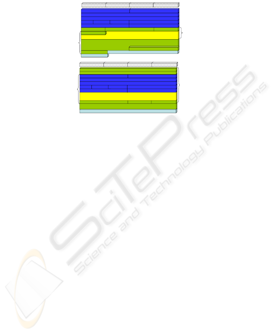
voice service or for a simultaneous data application. Figures 7 and 8 show the fields
in the packets to which integrity and encryption is applied.
Another difference between IPsec and SRTP is that IPsec encrypts the RTP
header, whereas SRTP does not. The advantage of using IPsec is that it hides useful
information from a potential attacker. The disadvantage is that it limits the ability of
firewalls and session border controllers (SBCs) to apply pinholes based on the port
88
numbers. This especially becomes critical for firewalls and SBCs that act as Network
Address Translation (NAT) devices for multiple subtended LCCs. Since the IP
address of all arriving VoIP packets are destined for the firewall or SBC, the only
discriminator (besides the flow label) that the firewall or SBC can use in determining
the appropriate LCC destination is the port number. In many commercial VoIP
implementations the flow label is zeroized to ensure that it is not used as a covert
channel.
Both protocols support similar encryption, authentication, and integrity
mechanisms. For instance, both protocols support the use of public key encryption,
the Advanced Encryption Standard (AES), and the keyed-Hash Message
Authentication Code – Secure Hash Algorithm (HMAC-SHA1). Therefore, there is
no difference in security from this perspective.
Session Setup, Rekeying, and Resumption Delays
To avoid excessive session setup times and clipping (loss of packets at the beginning
of a voice session) it is imperative that the bearer stream encryption key be distributed
as part of the signaling process. The IETF has defined an approach for distributing the
SRTP key as part of the SIP signaling process by placing the key in the Session
Description Protocol (SDP) body of the SIP message. The IETF at this point has not
developed a mechanism for SDP to distribute the encryption key for IPsec. In
addition, the offer/answer model in RFC 3264 may preclude including the IPsec key
information in the SIP signaling messages [6].
Frame Check Sequence
Authentication Tag
Voice (G.711 with 20 msec packet size)
(160 Bytes)
Encrypted Payload is same size as Plain Text Payload
Synchronization Source
Time Stamp
V
P X
CC
M
Payload Type Sequence Number
Byte 1 Byte 2 Byte 3 Byte 4
Integrity Covered
Encryption Covered
SRTP
Frame Check Sequence
Integrity Check Value (Variable)
Padding (0 – 128 bytes) Pad Length Next Header
Voice (G.711 with 20 msec packet size)
(160 Bytes)
Encrypted Payload is same size as Plain Text Payload
Synchronization Source
Time Stamp
V
P X
CC
M
Payload Type Sequence Number
Length Checksum
Source Port Destination Port
Sequence Number
Security Parameter Index (SPI)
Byte 1 Byte 2 Byte 3 Byte 4
Integrity Covered
Encryption Covered
RTP with IPsec
Fig. 7. RTP Integrity and Encryption Comparison.
Another consideration is the delay associated with rekeying. Recent studies have
compared rekeying times of a TLS session and an IPsec session and have shown that
IPsec takes approximately 20 times (26 ms versus 1.3 ms) as long to rekey as TLS
[1]. This is not a long period for a single rekey, but may be a concern if thousands of
end instruments attempt to rekey simultaneously.
89
Integrity Covered (Does
Not Include Length Field)
Encryption Covered
(Does not Include Length
Field or Data Link Trailer)
Frame Check Sequence
Pad Length
Frame Check Sequence
HMAC-SHA-1
SIP Payload (1,172 bytes)
Size Varies & Worst Case Largest Packet Example Used (Achieve 1280 byte MTU)
Average Packet ~ 600 bytes
Length
Type Version Length
Length Checksum
Offset Unused Control Bits Receive Window
Acknowledgement Number
Sequence Number
Source Port Destination Port
Byte 1 Byte 2 Byte 3 Byte 4
Pad (0-128 bytes)
SIP with TLS
Byte 1 Byte 2 Byte 3 Byte 4
Frame Check Sequence
Integrity Check Value (Variable)
Padding (0 – 128 bytes) Pad Length Next Header
SIP Payload (1,172 bytes)
Payload chosen to be consistent with SIP with TLS
Average Packet ~ 600 bytes
Length Checksum
Offset Unused Control Bits Receive Window
Acknowledgement Number
Sequence Number
Source Port Destination Port
Sequence Number
Security Parameter Index (SPI)
Integrity Covered
Encryption Covered
SIP with IPsec
Fig. 8. SIP Integrity and Encryption Comparison.
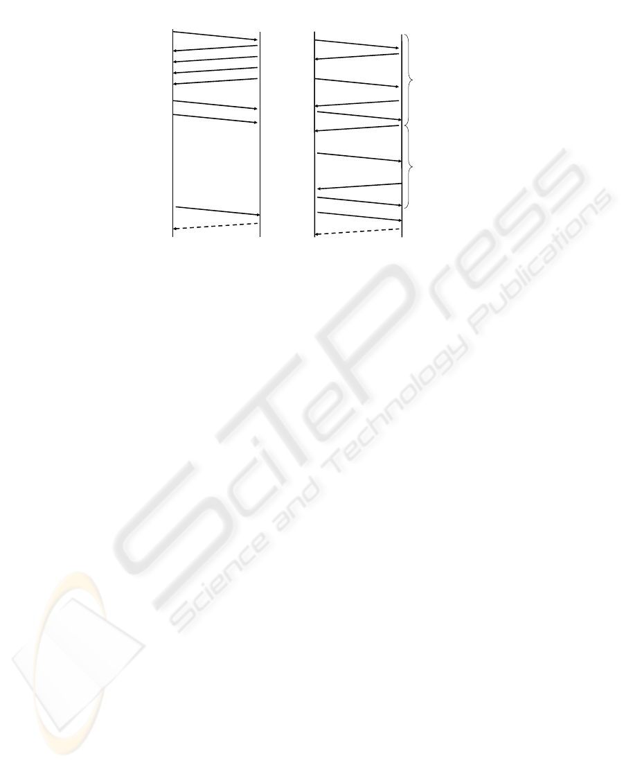
The final consideration is the delay associated with resuming a secure session. SIP
using TLS requires a minimum of six message exchanges. SIP using IPsec session
resumption is mainly associated with the Internet Key Exchange (IKE) process and
will depend on whether Main, Base or Aggressive mode is used for the Phase 1
exchange. Assuming that the Main mode is used, IPsec requires nine message
exchanges. Assuming that the one way latency within a region is approximately 85
ms, the addition of 3 extra messages would incur a latency penalty of 255 ms [9].
Figure 8 shows a comparison of the message exchanges required to resume a session.
After the Security Association is established, the SIP session establishment would
proceed as depicted in Figure 2.
Industry and Academic Interest
Industry and the academic community have already invested heavily in the standards
associated with the use of TLS to secure SIP and SRTP to secure RTP. Industry has
not currently invested in the use of IPsec to secure SIP and RTP. Both TLS and IPsec
are addressed in the SIP standard (RFC 3261) as a mechanism for security. However,
the SIP standard recommends TLS if a hop-by-hop security model is used or if the
security protocol is coupled with the VoIP application. IPsec is recommended in the
SIP standard when the application is decoupled from the security mechanism. Most
VoIP vendors currently couple the security mechanisms with the VoIP application. In
addition, the number of Internet Drafts and RFCs related to SIP and TLS, and RTP
and SRTP, and how SIP/TLS can interoperate with RTP/SRTP are significantly
greater than the Internet Drafts and RFCs related to the use of IPsec to secure both
SIP and RTP. This is an indication that academia and industry is currently more
interested in discovering and resolving issues related to TLS and SRTP for securing
VoIP.
90
Client
Server
Client Hello
Server Hello
Certificate
Change Cipher Spec
Finished (Encrypted)
Change Cipher Spec
Finished (Encrypted)
TLS Session Resumption
Initiator
Responder
Header, Security Association
IPsec Session Resumption
Header, Security Association
Header, [Hash]
Header, Key, <ID> Public
Key, <NONCE> Public Key
Header, Key, [HASH], <ID>
Public Key, <NONCE>
Public Key
Header, [Hash]
Phase 1
Header, {[HASH], Security
Association, NONCE, [KEY]
[ID, ID]}
Header, {[HASH], Security
Association, NONCE, [KEY]
[ID, ID]}
Header, {HASH}
Phase 2
SIP INVITE
SIP INVITE
Rest of SIP Messages
Rest of SIP Messages
Fig. 8. TLS and IPsec Session Resumption Comparison.
Network Management
The primary advantage of SRTP over IPsec is that the UDP and RTP headers are
exposed to network management personnel for the purposes of troubleshooting
network related problems. IPsec encrypts these headers, which eliminates this
information as a troubleshooting source. The principle mechanism for looking at this
discriminator is a packet sniffer tool, which would primarily be used to ensure that the
packet is appropriately formatted for the session. This is a useful tool, but may not be
a discriminator in choosing SRTP over IPsec. From a network management
perspective, IPsec and TLS are comparable.
Topology Hiding
IPsec offers an advantage over TLS and SRTP in terms of topology hiding since IPsec
has the ability to encapsulate the original header within the encrypted payload when
implemented using the tunnel mode. TLS and SRTP do not have an equivalent
functionality and must rely on an external Network Address Translator (NAT) device
for this functionality. However, most VoIP implementations will not take advantage
of the tunnel mode option and will likely use the transport mode, which does not
provide this functionality.
4 Conclusions
Based on our preliminary comparison between using IPsec versus TLS and SRTP for
VoIP, it is recommended that implementers use TLS and SRTP to secure their
solutions. This approach is easier to implement and maintain, consistent with industry
and academic investment, and is more bandwidth efficient than the IPsec approach.
There is no significant security advantage for using IPsec in comparison to TLS and
SRTP.
The preliminary considerations were based on an analysis of existing standards,
current TLS and SRTP vendor VoIP implementations, and research oriented IPsec
91

and previously published IPsec, TLS, and SRTP comparisons. However, published
studies that compare an implementation of IPsec to TLS/SRTP for secure voice
sessions on a level playing field do not currently exist or are limited and provide a
fertile ground for additional research. One objective of the study should address
efficient mechanisms to convey the IPsec keying information in the SIP messages and
compare the security and performance for each approach.
References
1. Alshamsi, A., and Saito, T., 2004, “A Technical Comparison of IPSec and SSL,” Tokyo
University of Technology, 2004 Symposium on Cryptography and Information Security.
2. Baugher, M., McGrew, D., Naslund, M., Carrara, E., and Norrman, K., “The Secure Real-
time Transport Protocol,” RFC 3711, March 2004.
3. Dierks, D., and Rescorla, E., “The Transport Layer Security (TLS) Protocol Version 1.1,”
RFC 4346, April 2006.
4. International Telecommunications Union, “H.323 - Infrastructure of audiovisual services –
Systems and terminal equipment for audiovisual services,” June 2006.
5. Kent, S., “IP Encapsulating Security Payload (ESP),” RFC 4303, December 2005.
6. Orrblad, Joachim, “Alternatives to MIKEY/SRTP to Secure VoIP,” Telecommunications
System Laboratory, KTH Microelectronics and Information Technology,
http://www.minisip.org/publications/Thesis_Orrblad_050330.pdf, March 2005.
7. Rosenberg, J., Schulzrinne, H., Camarillo, G., Johnston, A., Peterson, J., Sparks, R.,
Handley, M., and Schooler, E., “Session Initiation Protocol (SIP),” RFC 3261, June 2002.
8. Stenbit, J., “Internet Protocol version 6 (IPv6),” Chief Information Officer Memorandum, 9
June 2003.
9. “Wide Area Network (WAN) Generic System Specification (GSS)”, DoD Real-Time
Services Working Group, March 2007.
10. Vatn, J., Bilien, J., Eliasson, E., and Orrblad, J., “Secire VoIP: Call Establishment and
Media Protection”, Royal Institute of Technology, Stockholm, Sweden.
11. “Y.1541 – Series Y: Global Information Infrastructure, Internet Protocol Aspects and Next
Generation Networks – Network Performance Objectives for IP-based Services”,
International Telecommunication Union, February 2007.
92
