Formal Semantics for Property-Property Relations in
SEAM Visual Language: Towards Simulation and
Analysis of Visual Specifications
Irina Rychkova and Alain Wegmann
School of Communication and Computer Science
´
Ecole Polytechnique F
´
ed
´
erale de Lausanne (EPFL)
CH-1015 Lausanne, Switzerland
Abstract. SEAM is an enterprise architecture method that defines a visual lan-
guage for modeling. Our goal is to provide formal semantics for SEAM. Model
simulation, model comparison, and refinement verification are practical benefits
we expect from this formalization. This paper complements the existing SEAM
semantics by formalizing
property-property relations
. This formalization is based
on the theory of multi-relations and Relation Partition Algebra (RPA).
1 Introduction
In enterprise architecture projects, an enterprise, its environment, and its information
systems are analyzed and designed. In general, the EA frameworks such as ISA [1],
TOGAF [2] (for a more exhaustive list, see also [3]) do not propose a visual modeling
notation. SEAM (Systemic Enterprise Architecture Methodology)[4] is a visual EA
S
S2
S1
P1 P2
A B
H
AC
C
Property
Activity
Action
Property -property relation
Action-Action relation
Action-property
relation
System (Working Object)
Collaboration
Fig.1. SEAM visual notation.
method, based on Systems Thinking principles [5]. SEAM represents an enterprise and
its environment as a hierarchy of systems (e.g. market, company, IT system, etc.)[4].
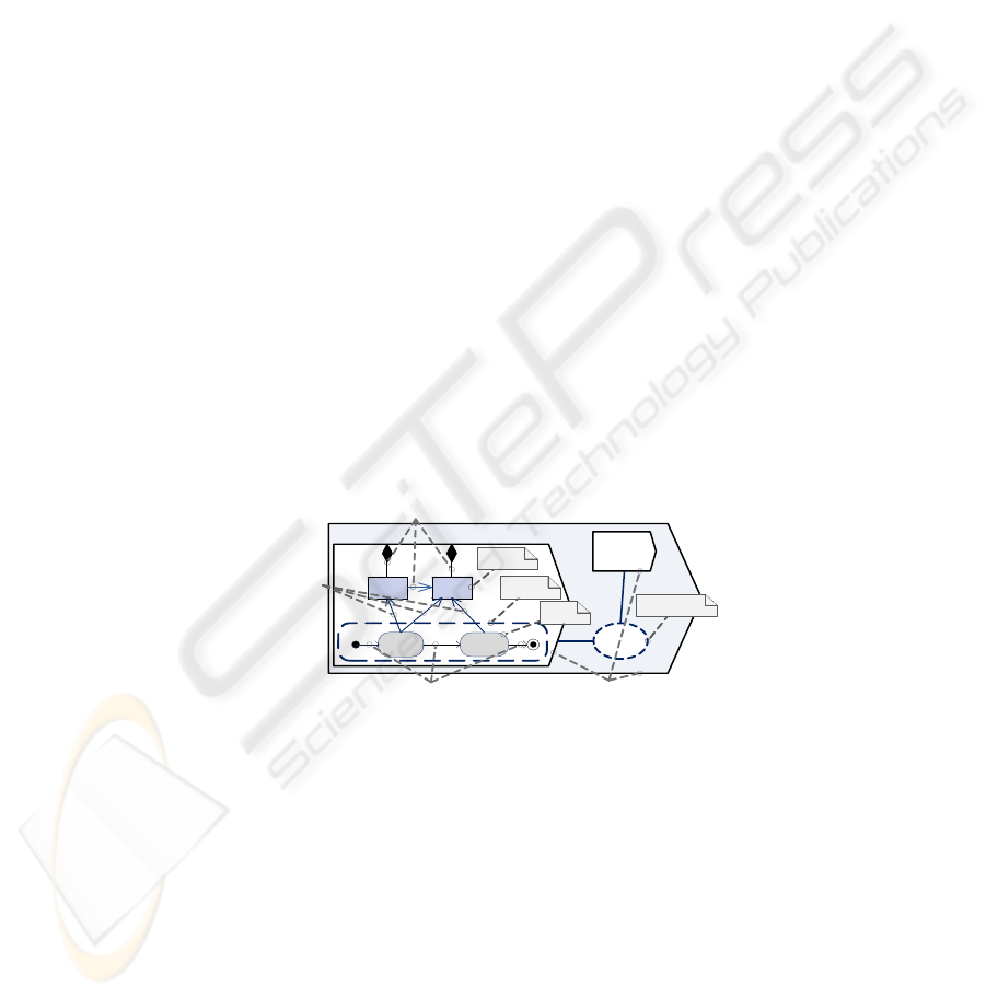
Figure 1 illustrates the SEAM visual notation: System S is modeled as a collaboration of
two systems S1 and S2. System S1 is described by its observable
properties
P1, P2, and
a behavior. The latter is represented by a set of
actions
A, B organized within
activity
AC. SEAM specifies three types of relations between its elements:
property-property
relations
,
action-action relations
, and
action-property relations
.
Our current research focuses on the definition of formal semantics for the SEAM
visual language. In software engineering, formal methods have been successfully used
Rychkova I. and Wegmann A. (2007).
Formal Semantics for Property-Property Relations in SEAM Visual Language: Towards Simulation and Analysis of Visual Specifications.
In Proceedings of the 5th International Workshop on Modelling, Simulation, Verification and Validation of Enterprise Information Systems, pages
138-147
DOI: 10.5220/0002435501380147
Copyright
c
SciTePress

in combination with UML[6] to formalize its visual notation, and to provide means for
model analysis [7],[8]. However, to our knowledge, no such experience in the domain
of EA is reported in literature. Model simulation [9], refinement verification [10], and
model comparison for SEAM specifications are the main benefits we expect from this
formalization.
In our previous work [10], formal semantics for SEAM properties, actions, activi-
ties, and action-property relations (Fig. 1) have been defined using higher-order logic
and Refinement Calculus [11]. To complete the formalization of SEAM, the semantics
for property-property relations and action-action relations has to be provided. This pa-
per introduces a formal semantics for property-property relations, based on the Relation
Partition Algebra (RPA)[13] and on the theory of multi-relations [12]. This semantics is
especially useful for refinement propagation technique, explained in [10]: introduction,
elimination, or modification of model elements (including property-property relations)
affects the model correctness and consistency and requires model adjustments. Refine-
ment propagation technique is based on the formal semantics of model elements. It
defines the set of rules to enforce model consistency and correctness and allows to au-
tomate aforementioned adjustments.
This paper is organized as follows. In Section 2 we introduce the SEAM visual
language and define its main modeling concepts. In Section 3 we present in more de-
tails the three types of relations defined in SEAM. In Section 4 we provide an exten-
sion of Relation Partition Algebra and the theory of multi-relations that formalizes the
property-property relations in SEAM. Based on this formalization, we specify the con-
sistency criteria for SEAM specifications. In Section 5 we discuss the related work.
Section 6 presents our conclusions.
2 The SEAM Visual Modeling Language
The SEAM ontology is based on the second part of the RM-ODP [14] specification.
Based on this standard, the main modeling concepts such as property, state, action are
defined. We briefly introduce these concepts below. For a detailed explanation, see [15].
Any system or system component in SEAM is modeled as a working object. We
distinguish between the following views of a working object:
- Working object as a whole - a black box system specification;
- Working object as a composite - a white box system specification.
A working object as a whole
1
describes a system by a number of properties
P
1
. . .P
m
that specify data types, and behavior
B .
We distinguish between primitive and compound properties. The former can be con-
sidered as an alias for an operational data type (e.g. Int, String, Boolean, etc.); the latter
is defined by a set of
component properties
and
references
to properties using
property-
property relations
.
A state of the primitive property denotes a value of the corresponding operational
type (e.g. 1, ”ABC”,true); a state of the compound property is defined by the states of
its components and references.
1
in this paper, we focus on modeling the working object as a whole and do not consider the
working object as a composite, therefore the identifier ’as a whole’ can be omitted
139

A tuple of property instances and their corresponding values defines a system state
σ ∈ Σ, where Σ specifies a state space - a set of all possible states of the modeled system.
A system state can be changed by a system behavior.
Behavior
B of a working object can be seen as an action or as an activity.
Action A is defined by a three-tuple {Pre,U, Post}. Precondition Pre specifies a set of
system states σ ∈ Σ where A is applicable. Postcondition Post specifies a set of system
states σ
′
∈ Σ after the application of A. U specifies a state transition and is called update.
Pre-, post- conditions, and updates are modeled as annotated
action-property relations
.
Activity Ac can be considered as a detailed specification of action A: it describes how
the transition from pre- state to post- state is performed. Ac defines a set of component
actions and the way they are composed to carry out the transition:
Ac ˆ= A
1
A
2
. . . A
t
where stands for component action ordering. This ordering is defined by
action-
action relations
.
3 The Three Types of Relations in SEAM
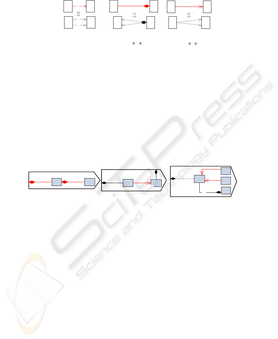
Action-Action(AA) Relations. SEAM specifies AA-relations using the BPMN [16]
notation. Figure 2 illustrates activity AC1 composed of four actions: A, B,C, and D.
AH
H
B
C
D
AC1
Start End
and-split
or- joint
Fig.2. Action-action relations.
An activity starts with a control action, called ’Start’ and finishes with a control action
’End’. Actions A and B are connected by a transition relation that specifies a sequen-
tial invocation of B after A terminates. Action B is connected with its successors by an
and-split relation, which specifies that actionsC and D are performed in parallel. Based
on a joint-type (or-joint) of the last AA-relation towards the End symbol, the activity
will terminate after at least one of the actions - C or D - terminates. We will address the
formalization of AA-relations in our future work.
Action-Property(AP) Relations. Contrary to languages like UML [6], in which di-
agrams are specialized (e.g. class diagram, state diagram, activity diagram), SEAM
describes system behavior and data structure within one diagram and provides explicit
relations between them (Fig. 3). A group of expressions on the destination end speci-
fies an information, useful for specification simulation.
Target expressions
specify the
relation type: Pre-, Post- conditions, or Updates;
instance expressions
specify the in-
stance names to be used by the corresponding target expressions;
select expressions
(optional) specify the instance choice providing multiple instances available. In UML,
this information is usually provided by annotated OCL[22] expressions.
Action GDiv in Fig. 3 specifies a division operation and selects the greatest devisor
if more then one is available.
140

S
GDiv
Divisor
{Int}
Dividend
{Int}
*
Target
Expression
Instance
Expression
Selection
Expression
y
Let y | forAll i instOf(Divisor) i<=y;
Pre: y
0
x
U:
x:=x/y
…. ….
*
Data
Structure
Behavior
Fig.3. Action-property relations annotated with instance, selection, and target expressions.
Property-Property (PP) Relations. Relation Partition Algebra (RPA) [13] defines ’part-
of’ and ’use’ relations as a special type of binary relations. These terms can be used to
represent PP-relations in SEAM. Consider a system data structure defined by a number
of data types (properties). The modularization of the data types (definition of compound
properties) gives rise to the part-of relations (Fig. 4-b, 5-a). Mechanism, when one prop-
erty references (uses) another, can be modeled by use relations (Fig. 4-c)Fig. 5-b).
In SEAM, part-of relations are used to designate the context, in which a property
exists. These relations are depicted by a line with a ’black diamond’ at its destination
end and an expression at its source end, to be read ”[source] is a part of [destination]”.
Use relations are depicted by a line with an expression at its destination end, to be
read [source] references (uses) [destination]. Expressions specify relation multiplicity
(usually, an integer-valued interval with a possibly infinite upper bound) and a list of
instance names. The multiplicity constrains the minimum and the maximum allowable
number of instances of a given property in the system. The multiplicity of the opposite
relation end is constant and equal to 1
in the SEAM specifications (usually omitted).
4 Formalization of Property-Property Relations Using RPA
The Relation Partition Algebra (RPA) by Feijs and van Ommering [13] defines part-
of and use relations as special types of binary relations. The theory of multi-relations
by Feijs and Krikhaar [12] defines a formalism, suitable for reasoning about relation
multiplicities. We combine these theories and formalize PP-relations in SEAM as
part-
of
and
use
relations with multiplicities that can be also called SEAM multi-relations.
4.1 SEAM Multi-Relations
Multi-relation m(x, y) = n (Fig. 4-a), defined in [12], specifies n occurrences of the
binary relation (x, y). Where x ∈ X, y ∈ Y - are elements of corresponding sets.
SEAM multi-relations part and use (Fig. 4-b,c) between properties P and Q, and
P and T, where P, Q, T ∈ P, specify ’relations with multiplicities’ between instances
x : P, y : Q, z : T of corresponding properties.
SEAM multi-relations part and use on P are defined by pairs of total functions:
part
inf
, use
inf
: P × P → N ∪ {∞}, part
sup
, use
sup
: P × P → N ∪ {∞} (1)
0 ≤ part
inf
≤ part
sup
≤ ∞, 0 ≤ use
inf
≤ use
sup
≤ ∞
141
yx
1
n
...
m(x,y) = n
x
n1
Q
...
P
y
part
inf
(P,Q) = n
1
part
sup
(P,Q) = n
2
x
n
n
1
n n
2
z
r1
T
z
r
...
P
x
use
inf
(P,T) = r
1
use
sup
(P,T) = r
2
r
1
r r
2
(a)
(b) (c)
yx
n
n
1
..n
2
| x
n1,..,
x
n2
QP
r
1
..r
2
|z
r1..
z
r2
TP
Fig.4. SEAM multi-relations. a) binary multi-relation; b) SEAM ’part-of’ relation: ’P is a part of
Q’; c) SEAM ’use’ relation: ’P uses T’. Above: short notation, below: detailed notation.
There are at least n
1
and at most n
2
instances of property P for each instance of Q:
part
inf
(P, Q) = n
1
, part
sup
(P, Q) = n
2
⇔ ∀ y : Q ∃ x
1
, .., x
n
: P | n
1
≤ n ≤ n
2
(2)
There are at least r
1
and at most r
2
instances of property T used (or referenced) by each
instance of property P:
use
inf
(P, T) = r
1
, use
sup
(P, T) = r
2
⇔ ∀ x : P ∃ z
1
, .., z
r
: T | r
1
≤ r ≤ r
2
(3)
Above, n and r are the corresponding
actual
number of instances.
Example 1. Figure 5-a illustrates the part-of relation between properties P and Q:
part
sup
(P, Q) = M
1
; part
inf
(P, Q) = 0 , where
’
P
is a part of
Q
’
and there exist at most
M
1
instances of P for each instance of Q. x
1
, .., x
M
1
- is a list of available instance names.
Spec1
Q
1..M|y
1
..y
M
P
0..M
1
|x
1
..x
M1
(a) (b)
Spec2
P
1..M|x
1
..x
M
T
0..M
1
|t
1
..t
M1
0..M
2
|y
1
..y
M2
Q
X
P
1..M|x
1
..x
M
T
W
0..M
3
|z
1
..z
M3
0..M
4
|y
1
..y
M4
Spec3
(c)
Fig.5. Property-property relations annotated with multiplicity and instance expressions. a) part-
of relations; b) use relation; c)Well-formedness of PP-relations.
Example 2. Figure 5-b illustrates the use relation between properties P and T:
part
sup
(P, T) = M
2
; part
inf
(P, T) = 0 , where
’
P
references (uses)
Q
’
and there exist
at most M
2
references on T for each instance of P. y
1
, .., y
M
2
- is a list of available
reference names.
Similarly to [13], we define a relation composition ◦ of SEAM multi-relations (Fig. 6:
sm
1
◦ sm
2
= {(P, R) | ∃Q ∈ P • sm
1
(P, Q) ∧ sm
2
(Q, R)} (4)
Identity relation I is a neutral element: I ◦ sm = sm◦ I = sm.
For properties P, Q, R ∈ P we write:
(sm
1
◦ sm
2
)
inf
(P, R) =
∑
Q∈P
sm
1inf
(P, Q) · sm
2inf
(Q, R)
(sm
1
◦ sm
2
)
sup
(P, R) =
∑
Q∈P
sm
1sup
(P, Q) · sm
2sup
(Q, R)
I
sup
(P, Q) = I
inf
(P, Q) = 0 if P 6= Q
142

where the following holds:
(sm
1
◦ sm
2
) ◦ sm
3
= sm
1
◦ (sm
2
◦ sm
3
) = sm
1
◦ sm
2
◦ sm
3
We define the exponentiation for SEAM multi-relations on P as sm
n
= sm◦ sm.. ◦ sm
(n-times), putting sm
0
= I - identity relation.
n
3
..n
4
QBP k
3
..k
4
R
sm
1
sm
2
(sm
1
sm
2
)
inf
(P,R) = (n
1
k
1
) + (n
3
k
3
) + (n
5
k
5
)
QC
QA
n
1
..n
2
n
5
..n
6
k
1
..k
2
k
5
..k
6
sm
1
sm
1
sm
2
sm
2
sm
1
= sm(P, _ ) sm
2
= sm( _ , R)
(sm
1
sm
2
)
sup
(P,R) = (n
2
k
2
) + (n
4
k
4
) + (n
6
k
5
)
P
0..n
I
inf
(P,P) = 0
I
sup
(P,P) = n
I
(a)
(b)
Fig.6. a) SEAM multi-relation composition. sm
1
- a relation with source P, sm
2
- a relation with
destination R; b) Identity relation.
We define a transitive closure sm
+
(P
1
, P
2
) on P iff there exists a sequence of ele-
ments Q
i
∈ P, i = 1..n such that P
1
= Q
1
and
sm(Q
1
, Q
2
) ◦ . . . ◦ sm(Q
n−1
, Q
n
) ◦ sm(Q
n
, P
2
) = sm
n
(P
1
, P
2
).
sm
+
inf
=
∞
n=1
sm
n
inf
and sm
+
sup
=
∞
n=1
sm
n
sup
(5)
Here sm
n
(P
1
, P
2
) is an n-step path from P
1
to P
2
.
4.2 ’Part-Of’
A part-of relation between properties P and Q (Fig. 4-b) specifies the fact that property
P is a part of a data type, defined by property Q (see Example 1). Property P can be a
part of one and only one compound property, i.e. part-of relations is functional:
∀ P, Q, R ∈ Ppart
sup
(P, Q) > 0 ∧ part
sup
(P, R) > 0 ⇔ Q = R (6)
Property P cannot be a part of itself, and there is no path of one or more legs that starts
at P and leads back to P, i.e. part-of relations is cycle-free, as defined in [13]:
∀P ∈ P part
+
(P, P) =
/
0 (7)
We define a part-of relation between a property and a system (a working object):
part
sup
: P → N ∪ {∞}, part
inf
: P → N ∪ {∞} (8)
Here, part-of relation specifies a collection of instances of P provided by the system.
These instances can be identified with the global variables of the system.
Example 3. Figure 5-a illustrates the part-of relation where
’
Q
is a part of
Spec1
’
and
there exist at most M instances of Q in Spec1: part
sup
(Q) = M; part
inf
(Q) = 1, and
y
1
, .., y
M
- is a list of available instance names.
Dynamic creation and deletion of property instances is an important issue that can be
specified on the diagram, using part-of relations, prior to model simulation.
143

Example 4. In Fig.5-a, consider some action CreateQ that creates instances of property
Q, action DeleteQ that deletes them, and M
act
- the actual number of instances of Q in
the system (i.e. a number of y
i
at a given moment of simulation), where 1 ≤ M
act
≤ M.
Using multiplicities, the effect of creation of an instance y
i
can be expressed by the
following statement: M
act
:= M
act
+ 1. For instance deletion we can write: M
act
:= M
act
− 1.
This can be interpreted as follows:
1)If M ∈ N is a constant - every time, after a new instance of Q is dynamically created,
one more name y
i
is taken from the list of available instance names y
1
..y
M
. When M
act
=
M - CeateQ must not be available any more.
2)If M = ∞ - CreateQ is not restricted.
3) Every time one instance of Q is deleted, one name y
i
is put back to the list y
1
..y
M
.
When M
act
= 1 - DeleteQ must not be available any more.
We generalize the assertion that part-of relation is functional eq.(6) for the part-of rela-
tion compositions:
Lemma 1. For each ordered pair of properties < P
1
, P
2
> there exists at most 1 se-
quence of properties Q
1
, .., Q
n
∈ P with P
1
= Q
1
and a corresponding sequence of part-
of relations
part(Q
1
, Q
2
) ◦ . . . ◦ part(Q
n−1
, Q
n
) ◦ part(Q
n
, P
2
) = part
n
(P
1
, P
2
)
such that part
n
(P
1
, P
2
) ≡ part
+
(P
1
, P
2
).
Here part
n
(P
1
, P
2
) is a path from P
1
to P
2
of the length n, where ’P
1
is a part of Q
2
, and
Q
2
is a part of Q
3
, and .. and Q
n
is a part of P
2
’.
This lemma stipulates that between two properties can be found at most one sequence
of ’part-of’ relations of an arbitrary length and this sequence is linear.
We can generalize the definition of part-of relations for relation composition:
Definition 1. If for two properties P and Q there exists some n > 0 such that part
n
(P, Q)
6=
/
0 then Q contains P as a part.
Corollary 1. For each property P there exists at most one property Q ∈ P such that Q
contains P as a part, and part
n
max
(P, Q) = part
+
(P, Q) 6=
/
0 Here n
max
- is the longest
path that starts at P and finishes at Q.
By Lemma 1 and Corollary 1 we can calculate the maximum and minimum number of
instances of property P in the system S:
Inst
max
(P) = part
sup
(P) +
∑
Q∈P
part
+
sup
(P, Q) · part
sup
(Q) (9)
Inst
min
(P) = part
inf
(P) +
∑
Q∈P
part
+
inf
(P, Q) · part
inf
(Q) (10)
4.3 ’Use’
A use relation between properties P and T (Fig. 4 -c) specifies the fact that property
P references property T (see Example 2). Property T can be referenced by multiple
compound properties, i.e. use relations is non-functional:
∃ T, P, P
′
∈ P | P 6= P
′
• use
sup
(P, T) > 0 ∧ use
sup
(P
′
, T) > 0 (11)
144

Property T can be referenced by itself, i.e. use relations can be cyclic as defined in [13]:
∃ T ∈ P | use
+
(T, T) 6=
/
0
We can calculate the number of references to T in the system:
∀ P
i
| use
sup
(P
i
, T) > 0, Ref(P
i
, T) = Inst
max
(P
i
) · use
sup
(P
i
, T) (12)
and the maximum number of references:
Ref
max
(T) = max
P
i
(Inst
max
(P
i
) · use
sup
(P
i
, T)) (13)
4.4 From Property-Property Relations to Specification Well-Formedness and
Consistency
PP-relations define a data structure in SEAM specifications. To obtain the well-formed
data structure, the following must be ensured for each system property P:
-Property P can be a part of one and only one compound property or a working object;
-Property P cannot be a part of itself, and there is no path of two or more legs that starts
at P and leads back to P.
Formalization of PP-relations enables us to detect errors concerned with data structure
inconsistency
. For example, an instantiation deficiency, when for some property P the
number of declared instances in the specification Inst
max
(P) is less then required by the
system (specified by references from other properties):
∃ Q ∈ P | Re f
max
(Q, P) > Inst
max
(P)
Example 5. In Fig. 5-c, property P is referenced by two properties T and W. To avoid
instantiation deficiency, the specification must guarantee that max{M
4
, M
3
} ≤ M, i.e.
the number of references on P from either W or T must not exceed the number of
instances M of P, defined by the specification.
A free-floating property is a data type that is not instantiated in the system.
Definition 2. Property P is free-floating iff Inst
max
(P) = 0.
Example 6. In Fig. 5-c, properties T,W, Q are free-floating:
Inst
max
(T) = Inst
max
(W) = Inst
max
(Q) = 0.
A property
can
be specified as a free-floating, when the number of instances is not
important at a given level of abstraction. For example, a number of ’items for sale’
might be omitted in an abstract specification of a vending machine, since a behavior of
this machine is the same for each item.
If free-floating property P is
referenced
by some property Q, i.e.
∃ Q ∈ P | Ref
max
(Q, P) > 0
this causes an instantiation deficiency in the specification: Ref
max
(Q, P) > 0= Inst
max
(P).
We summarize with the following criteria of consistency:
System data structure defined by SEAM specification is consistent if:
1. all part-of relations in the specification are functional and cycle-free (i.e. eq.
(6)
and eq.
(7)
hold),
2. instance declaration is sufficient:
∀P ∈ P Ref
max
(P) ≤ Inst
max
(P) (14)
3. no reference on a free-floating property exists:
∀P ∈ P | Inst
max
(P) = 0 ⇒ use(P
i
, P) =
/
0 ∀ P
i
∈ P (15)
145

5 Related Work
The scientific publications, listed below, report some practical applications in the area
of visual model analysis based on a combination of visual and formal methods:
Pons [8] presents the OCL-based technique and a tool support for UML and OCL
model refinement. Object-Z is an underlying theory for refinement verification. The au-
thors discuss the refinement patterns and formulate the refinement conditions for these
patterns in OCL [22].
Muskens et al. [23] focuse on the problem of consistency checking between soft-
ware views, expressed as UML diagrams. The approach in [23] is based on verification
of obligations and constraint rules using relation partition algebra.
Modeling languages, listed below, consider formalization of their visual notation as
a bridge to model simulation.
OPM (Object-Process Methodology)[17] proposes a method for the complete inte-
gration of the system’ states and behaviors within a single graphical model. OPM dis-
tinguishes different types of relations between its model elements, similarly to SEAM.
An Object-Process Language (OPL) serves as a basis for generation an executable code
and a database schema and represents a formal semantics for OPM.
DEMO (Design & Engineering Methodology for Organizations) [18] is a method
for (re)designing organizations. DEMO provides a semantics for model simulation.
BPMN (Business Process Modeling Notation)[16] provides a visual notation for
business process modeling (BPM). SEAM action-action relations are defined based
on BPMN. Explicit bindings between a BPMN process and the data this process op-
erates on (represented by action-property relations in SEAM) is made by annotation
with BPEL constraints. BPEL (Business Process Executable Language)[19] was devel-
oped for business process model simulation and verification. An automated mapping of
BPMN diagrams to BPEL for further execution is supported by many commercial tools
(e.g. iGrafx, IBM WBI Modeler, etc - see
http://www.bpmn.org/
BPMN_Supporters.htm#current
for an exhaustive list). Formal semantics for business
process modeling was provided using Petri Net [20].
UML (Unified Modeling Language) [21], [6] defines a set of specialized diagrams
for its models. System behavior is addressed in UML by activity diagrams. The data
structure of a system is captured by UML class diagrams. A class diagram defines
classes, organized within a model using association, aggregation, composition, and in-
heritance relations. Part-of relation in SEAM can be identified with UML composition,
whereas SEAM use relation is defined by analogy with UML association. The semantics
of activity diagrams in UML 2.0 is based on Petri Nets[7]. However, there were many
attempts to define this semantics based on other formal languages: LOTOS, ASM, CSP,
LTS (see [7] for details).
6 Conclusion
In this work, we introduce the formal semantics of property-property (PP) relations in
SEAM visual language. This formalization enables us reasoning about consistency of
data structure.
146

In our previous work [10], the refinement propagation technique for SEAM visual
specifications has been introduced. The proposed algorithm explores the possible con-
flicts between model elements, caused by refinement, and applies specific rules of re-
finement propagation to enforce the model correctness.
Model refinement where property-property relations are eliminated, introduced, or
modified is not considered in [10] and can be captured using the theory proposed
in this work. Refinement propagation rules that enforce model consistency and well-
formedness, as defined at the end of section 4, can be introduced. For instance, such a
rule may forbid the user from deleting a part-of relation because it will lead to an instan-
tiation deficiency. Alternatively, an alert can be generated in the case of a creation of a
part-of relation if it leads to a cycle. Automated model refinement is the main practical
benefit expected from the proposed formal semantics.
References
1. Zachman J. A.: A Framework for Information Systems Architecture, IBM Systems Journal
(1987)
2. The Open Group Architecture Framework (TOGAF), The Open Group,(2006)
3. Schekkerman, J.: How to Survive in the Jungle of Enterprise Architecture Frameworks: Cre-
ating or Choosing an Enterprise Architecture Framework, Trafford, (2003).
4. Wegmann, A.: On the systemic enterprise architecture methodology (SEAM). In proceedings
of International Conference on Enterprise Information Systems (ICEIS) (2003)
5. Weinberg, G.M.: An Introduction to General Systems Thinking. Wisley & Sons (1975)
6. Unified Modeling Language (UML), v. 2.1.1. OMG (2007)
7. St
¨
orrle, H.: Semantics of UML 2.0 Activities, Proceedings of the IEEE Symposium on Visual
Languages and Human-Centric Computing (VL/HCC) (2004).
8. Pons, C.: Heuristics on the definition of UML refinement patterns. SOFSEM, (2006).
9. Rychkova, I., Wegmann, A.: A Method for Functional Alignment Verification in Hierarchical
Enterprise models. BUSITAL workshop in CAiSE (2006)
10. Rychkova, I., Wegmann, A.: Refinement propagation. Towards automated construction of
visual specifications. International Conference on Enterprise Information Systems (ICEIS)
(2007)
11. Back, R.-J., von Wright, J.: Refinement Calculus: A Systematic Introduction. Springer
(1998)
12. Feijs, L.M.G., Krikhaar R.L.: Relation algebra with multi-relations. International Journal of
Computer Mathematics.(1998)
13. Feijs, L.M.G., van Ommering, R.C: Relation partition algebra - mathematical aspects of uses
and part-of relations. Science of Computer Programming (1999)
14. Reference model of open distributed processing. Draft International Standard (DIS)(1995)
15. Wegmann, A., Naumenko, A.: Conceptual Modeling of Complex Systems Using an RM-
ODP Based Ontology. 5-th IEEE International Enterprise Distributed Object Computing
Conference (EDOC) (2001)
16. BPMN 1.0: Final Adopted Specification. OMG. (2006)
17. Dori, D., Object-Process Methodology, A Holistic Systems Paradigm. Springer (2002).
18. Dietz, J. L. G.: Enterprise Ontology Theory and Methodology. Springer (2006)
19. Business Process Execution Language for Web Services Version 1.1. The IBM. (2004)
20. van der Aalst, W.: Challenges in business process management: Verification of business pro-
cesses using petri nets. Bulletin of the EATCS.(2003)
21. Rumbaugh, J., Jacobson, I., and Booch, G.: The Unified Modeling Language Reference Man-
ual, Second Edition. Addison-Wesley. (2005)
22. OCL 2.0 Final Adopted Specification. OMG (2003)
23. Muskens, J., Bril, R.J., Chaudron, M.R.V.: Generalizing consistency checking between soft-
ware views. Conference on Software Architecture (WICSA), IEEE (2005)
147
