
UML-driven Information Systems and their Formal
Integration Validation and Distribution
⋆
Nasreddine Aoumeur and Gunter Saake
Otto-von-Guericke-Universit
¨
at Magdeburg
Institut f
¨
ur Technische und Betriebliche Informationssysteme
PF 4120, D–39016 Magdeburg, Germany
Abstract. Being the de-facto standard (object-oriented-OO) method(-logy) for
software-intensive systems development, UML with its different diagrams and
supporting tools represent nowadays the mostly adopted software-engineering
means for information systems (IS). Nevertheless, due to this wide-acceptance
by all organization stakeholders several enhancements at the modelling level are
required before adventuring into further implementation phases. The coherence
and complementarity between different diagrams have to tackled; On the basic
of such endeavored coherent global view, the consistency and validation of the
whole IS conceptual models are to undertaken; and last but not least as current
information systems are mostly networked and concurrent, UML-driven have to
cater for intrinsic distribution and concurrency.
To leverage UML-driven IS conceptual modelling towards these crucial enhance-
ments, we propose a semi-automatic intermediate abstract phase before any im-
plementation, we govern by a rigorous component-based operational and visual
conceptual model. Referred to as CO-NETS, this specification/validation formal-
ism is based on a tailored formal integration of most OO concepts and mecha-
nisms enhanced by modularity principles into a variant of algebraic Petri Nets.
For rapid-prototyping purposes, CO-NETS is semantically interpreted into rewrit-
ing logic. This UML-CO-NETS proposal for distributed IS rigorous development
is illustrated through a non-trivial case-study for production systems.
1 Introduction
With the networking of most organizations into cross-organizational giants, where emerg-
ing collaborations and interactions and are the driving forces, information systems (IS)
as the ”digitalized” accurate mirror of these new organizational interaction-driven re-
alities are consequently under extreme pressure to keep in pace with these advances.
For a reliable development of today’s IS integrated semi-formal and formal OO mod-
elling frameworks have been widely adopted, providing powerful abstraction mecha-
nisms for intrinsically integrating and building-on structural and behavioral features
(e.g. OMTROLL [1], fOOSE [2]).
⋆
This research is partially supported by a DFG (German Science Foundation) Project Under
Contract SA 465/31-1
Aoumeur N. and Saake G. (2007).
UML-driven Information Systems and their Formal Integration Validation and Distribution.
In Proceedings of the 5th International Workshop on Modelling, Simulation, Verification and Validation of Enterprise Information Systems, pages 63-73
DOI: 10.5220/0002435600630073
Copyright
c
SciTePress
This contribution fits within these efforts, and it proposes to extend the semi-formal
UML [3] method with more formality, global coherence, validation and distribution.
We thus propose a validation based on a sound framework which allows us to shift
from UML-driven IS conceptual modelling towards a fully distributed specification
consisting of cooperative components. We hence extend UML-diagrams for fulfilling
more advanced requirements including: (1) Intra- as well as inter-object concurrency;
(2) synchronous and asynchronous communication; (3) specification of components as
hierarchy of classes; (4) Explicit inter-component interactions without violating encap-
sulated part of each component; and (5) graphical animation accompanied by formal
concurrent reasoning.
The proposed framework for this advanced specification/validation phase is a new
form of component-based Petri nets model that we interpret in rewriting logic. Re-
ferred to as CO-NETS, this specification/validation formalism [4] is mainly character-
ized by the following key features: (1) To promote inter-communication and autonomy,
CO-NETS explicitly distinguishes between local aspects and external ones in a given a
component; (2) To enhance Behavior-centricity, we interact components through their
explicit interfaces; (3) CO-NETS semantics is interpreted in rewriting logic[5] which is
a true-concurrent operational semantics particularly allowing rapid-prototyping.
The rest of this paper is organized as follows. The second section informally intro-
duces the case study through which we illustrate the different phases of our proposal.
The third section presents UML class- object- and state-diagrams as well as OCL con-
straints in the form of pre- and post-conditions. In the third section we review the main
CO-NETS features we focus on subsequently. In the main section, we present our ideas
for shifting from these four diagrammatical views into a corresponding unique coherent
CO-NETS specification. The fourth section deals with the validation phase by illustrat-
ing how transition rewrite rules are automatically derived. We finally close this paper
with some concluding remarks and an outlook on future extensions.
2 The Holonic Transport Case Study
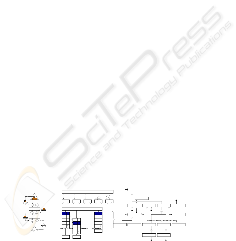
As depicted in the left-hand side of Figure below, we concerned with a part of a pro-
duction system where specific work pieces (OBJECT) are processed by three different
machines (M
x
) in a specific order. The transport of the work pieces is carried out by
so called ”Holonic Transport Systems” (HTS) which are mobile robots. Machines have
to initiate JOBs to execute transports of work pieces. These HTS have to be concur-
rent and self-organizing in a way that they locally decide by competing offers which
transport job they execute.
time-limit for
start
Machine 3
Machine 2
Machine 1
Entry buffer
Exit buffer
Machine 1
Machine 2
Machine 3 Holonic Transport System
Exit buffer
Entry buffer
negotiation
timeout
Holonic Transport System
-4
Calculate and broadcast offer
-
HTS3
HTS4
HTS5
HTS2
5
-
HTS3
HTS4
HTS5
HTS2
5HTS1 HTS3
HTS4
HTS5
HTS2
5HTS1HTS1
HTS 5HTS 2HTS 1 HTS 3 HTS 4
blocked malfunction
Send transport job to all HTS
available available available
Cancel
Cancel Approval
JOB
DEMANDOFFER
COMPONENT
MACHINEHTS
DESTINATION
BUFFER
SOURCE
EXITBUFFER ENTRYBUFFER
OUT IN
OBJECT
Object
Machine(mid: nat)
Object
Client
Job(jid: nat)
HTS(hid: nat)
Partner
CLOCK
Object(oid: nat)
OBJECT
Clock
OBJECT
DestinationSource
64

Additionally, there are two buffers in that scenario. The first one (IN) provides
“fresh” (entirely unprocessed) work pieces, whereas completely processed work pieces
are delivered into the second one (OUT). Every machine consists of local entry and
exit buffers which may store unprocessed/processed work pieces. Each time an object
is removed from the local entry buffer or inserted into the local exit buffer, the machine
calls for a HTS to deliver a new or remove a processed work piece. This way, we can
distinguish between demand- (DEMAND) and offer-jobs (OFFER).
A possible scenario is as like. A machine M
x
generates a request and sends it to-
gether with a time-stamp via broadcast to all HTS. When a HTS receives the request, it
first checks the current time and compares it with the requests time-stamp. If the elapsed
time lies below a certain time-limit, the HTS may proceed the negotiation process. If a
HTS is currently unable to perform the requested job for some reason it sends an unable
message to all other HTS and aborts the negotiation. Otherwise the offer is calculated,
sent to the other HTS and entered into an internal cost comparison table (CCT). Until
the time-limit is reached, all HTS collect the offers of the other HTS and enter them
into their CCT.
3 UML-Specification of the Case-study
We model here the class-diagrams to cover the static aspects and state diagrams de-
scription to represent the dynamic part of the specification [3].
3.1 Class and Object-diagrams
The right-hand side of the Figure above depicts the possible classes. The class COM-
PONENT, for instance, acts as a super-class for all active components (HTS, machines,
buffers). HTS have to control the flow of work pieces in the scenario. The class JOB
is an abstraction of a task a HTS must perform. Machines have local entry (SOURCE)
and exit-buffers (DESTINATION). A BUFFER models an abstract super-class to in-
sert, store, and release a (limited) number of work-pieces. Elements of class OBJECT
model the work pieces. They are identified using the attribute oid.
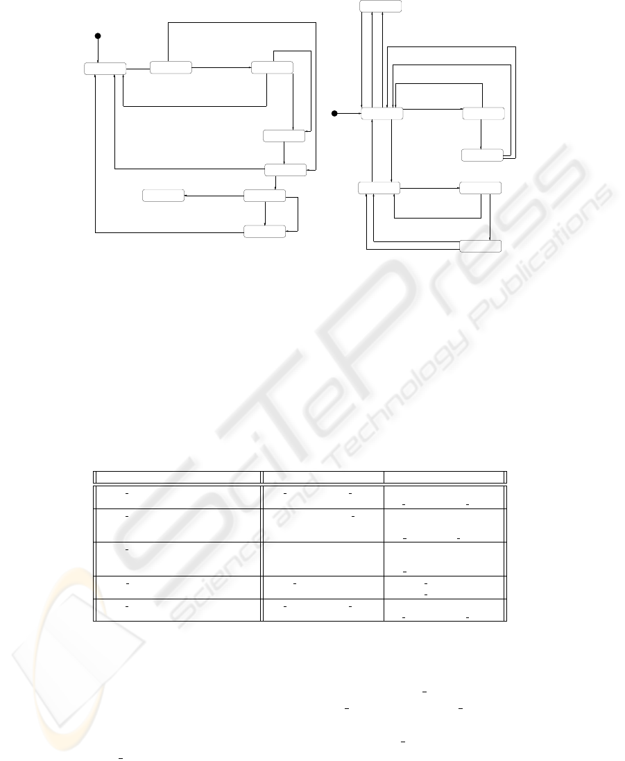
3.2 State Diagrams
With the behaviour state-diagram, different states of the objects in the scenario with
state transition rules depicting the necessary preconditions and events are described.
The Left-side of Figure 1 depicts the state diagram of the class HTS. By occurrence
of the birth event start the HTS changes its state into ready. Receiving a job request
from a machine in this state (receive
job) changes the HTS into the state received J.
In case a partner is required to perform the requested job, the HTS has to determine and
contact all possible partners for the job (request
Partner). Otherwise (e. g. if the HTS
already carries a requested work piece) it may directly calculate the offer by the event
calc
Offer and make thereby a transition into the state calculated. In the contacted
state, the HTS will have to wait until either all contacted partners have answered the
request or a predefined time-limit (rlimit) has elapsed. The remaining HTS at this time
may send the approval for the job (send
Approval).
65
ready demand
start
[Dest.free>0] next_Object
approved_D
[ntime<=nlimit] receive_ApprovalD
[Source.available>0] process_Object
processed
[Dest.free=0] send_JobO
offer
[ntime>nlimit] abort_Offer
[ntime<=nlimit] receive_ApprovalO
approved_O[rtime<=rlimit] deliver_Object
[ntime>nlimit] abort_ApprovedO
[Source.available=0] send_JobD
[ntime>nlimit] abort_Demand
requested
[rtime>rlimit] abort_ApprovedD
[rtime<=rlimit] receive_Object
send_Partner
[Source.available>0] receive_RequestO
[Dest.free>0] receive_RequestD
start
received_J contacted
received_A
calculated
[exist_offer AND ntime<=nlimit] send_Offer
[NOT exist_offer OR ntime>nlimit] send_Abort
[rtime>=rlimit OR cnt(answers)=max_answer] calc_Offer
sended
received_O
approved
[ntime<=nlimit] receive_Offer
[my_offer>best_offer] abort
[ntime>nlimit] send_Approval
[partner_required] request_Partner
[rtime<=rlimit] receive_Partner
[rtime<rtlimit AND cnt(answers)<max_answer] wait_Answer
[NOT partner_required] calc_Offer
[my_offer=best_offer] wait_Offer
receive_Job
[rtime>rlimit] send_Abort
ready
Fig.1. State Diagram of HTS and Machine Classes.
3.3 OCL- pre- Post-Constraints
We further judge that relevant to the modelling phase belongs also the dynamic de-
tail about different methods, namely their enabling pre-conditions and resulting post-
conditions. With the modelling of such methods features at the modelling level, we
result in more controlled implementation outputs, where the programmers have to be
bounded by a minimal conceptual constraints in developing the body of each meth-
ods. Pre- and Post-constraints are further crucial for our subsequent phase, where they
have to govern different transition input/output arc inscriptions and thereby the to-be-
conceived nets.
Method Name Pre-Constraint Post-Constraint
receive Job(j:JOB) send AbortA or send AbortB Jobs:=Jobs.insert(j),
calc OfferA, request Partner
receive Partner(m:MACHINE,costs:nat) rtime≤rlimit , request Partner answers:=answers+,
mk-set(mk-tuple(m,costs)),
wait Answer, calc Offer
receive Offer(h:HTS,costs:nat) ntime≤nlimit offers:=offers+mk-set
(mk-tuple(h,costs)),
wait Offer, abort
request Partner(j:JOB) partner required=true m.receive RequestD(self,j),
m.receive RequestO(self,j)
receive Job(j:JOB) send AbortA or send AbortB Jobs:=Jobs.insert(j),
calc OfferA, request Partner
With respect to the running case study, we depict in the following some of these pre-
and post-conditions to be associated with different methods related different classes in
the above discussed class-diagram. For instance, the receive job method should
preceded by the execution of the two methods send
AbortAand send AbortB. The
resulting output consists in incrementing the job list by the requested to-be-performed
job and by the triggering of the two following methods calc OfferA and
request
Partner.
66

After achieving this analysis / modelling phase, we have now to leverage it to more
cohesive view, where distribution, componentization, visual and symbolic validation
are intrinsic. The corresponding specification/validation framework we are putting for-
wards is CO-NETS, a tailored form of integration of OO structuring mechanisms with
high-level algebraic Petri nets that we soundly interpret in rewriting logic.
4 The CO-NETS Approach: An Overview
For the purpose of this paper and also due to space limitation, only some CO-Nets
1
aspects are reviewed in what follows. Reader is referred to [4] for more detail.
4.1 Component Structural Specification
States in CO-NETS are terms of the form hId|at
1
: v
1
, ..., at
k
: v
k
, bs
1
: v
′
1
, ..., bs
k
′
:
v
′
s
i; where Id is an object identity ; at
1
, .., at
k
are local and bs
1
, ..., bs
s
are observed
from other components.We further allows ’splitting / recombining’ this state at request.
Similarly, we explicitly distinguish between internal, local messages and the external as
imported/exported messages. Local messages allow for evolving the object states of a
given class, while the external ones allow for communicating between different classes
using exclusively their observed attributes.
4.2 Component Behavioral Specification
On the basis of this component signature, we define the notion of CO-NETS specifi-
cation incrementally as follows. CO-NETS places are precisely defined by associating
with each message generator (type) one place we call ’message’ place. We also asso-
ciate with each component sort one place that has to contain the current states within
such component. CO-NETS transitions reflect the effect of messages on the targeted
states. We further make distinction between local transitions that reflect state changes
and the external ones modeling the interaction between different components.
4.3 CO-NETS: Semantical Aspects
As general behavioral pattern for transitions, we propose that the effect of CO-NETS
transitions capture the following interaction-driven computation. The contact of state
parts in a given componentn Cl, —namely hI
1
|ats
1
i ;..; hI
k
|ats
k
i— with some mes-
sages ms
i1
, .., ms
ip
, ms
j1
, .., ms
jq
—declared as local or imported in this component—
and under some conditions on the invoked attributes and message parameters results
in the following effects: (1) Messages such as ms
i1
, .., ms
ip
, ms
j1
, .., ms
iq
vanish;
(2) State changes of some (parts of ) states participating in this computation, namely
I
s1
, .., I
st
; (3) Deletion of some states by sending explicitly delete messages; and new
messages are sent to the component Cl state, namely ms
′
h1
, .., ms
′
hr
, ms
′
j1
, .., ms
′
jq
.
1
An acronym for Concurrent Object oriented Petri Net.
67

Conditions on attributes values
and messages parameters
i1
. .
. .
..
j1
ms
ms
i1
ms´
ms´
ip
h1
hr
jq
ip
ms´
j1
ms´
jq
ms
j1
ms
jq
obj
T
Mes
Mes
Mes
Mes
Mes
hr
h1
. . . . .
Mes
hI
j
|at
j
: v
j
..i
hI
1
|ats
1
i.. ⊕ hI
k
|ats
k
i
hI
s
1
|ats
′
s
1
i.. ⊕ hI
i
1
|ats
′
i
1
i..
Fig.2. The Intra-Component Computation Pattern.
Rewriting rules governing the CO-NETS behaviour Each CO-NETS transition is cap-
tured by an appropriate rewriting rule interpreted into rewrite logic[5]. Following the
intra-component evolution pattern in figure 2, the general form of rewrite rules that we
associate with it takes the form below. The operator ⊕ is defined as a multiset union and
allows relating different place names with their current markings. Whereas the multiset
operator ⊗ allows composing different couples place-inscription, so that we can define
different input arcs and output arcs in a given transition. Moreover, we assume that ⊗ is
distributive over ⊕ i.e. (p, mt
1
⊕ mt
2
) = (p, mt
1
) ⊗ (p, mt
2
) with mt
1
, mt
2
multiset
of terms over ⊕ and p a place identifier.
T : (Ms
i
1
, ms
i
1
) ⊗ ..(Ms
j
q
, ms
j
q
)⊗ (obj, hI
1
|attrs
1
i ⊕ .. ⊕ hI
k
|attrs
k
i)
⇒ (Ms
h
1
, ms
′
h
1
) ⊗ ...(Ms
′
j
q
, ms
′
j
q
) ⊗ (obj, hI
s
1
|ats
′
s
1
i.. ⊕ hI
i
r
|attrs
′
i
r
i)
if Conditions and M (Ad
Cl
) = ∅ and M (Dl
Cl
) = ∅
We point out that more advanced component-based abstraction mechanisms have
been conceived for capturing inheritance, aggregation and interaction between compo-
nents [4].
5 From UML-driven IS to CO-NETS Components
After sketching the main concepts of the CO-NETS framework, we discuss in this main
section how to incrementally and (semi-)automatically derive a coherent view of dif-
ferent UML diagrams and OCL constraints based on CO-NETS components. First, we
present how structural features from class classes can be mapped to corresponding CO-
NETS component templates. Further, we address the translation of different behavioral
and dynamic diagrams and OCL constraints in the behavioral sides of the CO-NETS
framework.
5.1 From UML Classes to CO-NETS Components Structure
This translation mainly concerns attribute and message descriptions, and it can be made
precise through the following translating steps.
1. Different attributes associated with a given class-diagram are directly specified as
component states–as tuple terms— by gathering them together and enriching them
with the state identity part. Possibilities in restricting, initializing or fixing some
attributes values have to be expressed as conditions in the creation/deletion compo-
nent transitions.
68

2. In order to have just one and a uniform view, besides these stateless attributes
that are explicitly defined in the class-diagrams, explicitly defined states and their
changes from the state-diagram have also to be added to the tuple as stateful extra-
attributes.
3. All event / message generators will be regarded as messages by enriching their
arguments with identities of involved states. Moreover, by taking profit of the com-
munication diagram, all events that are to be sent to other classes have to be defined
as exported ones.
4. From the explicit effect of these external messages described in OCL- pre- and
post-conditions we straightforwardly conceive the observed attributes part as those
which are explicitly involved in such state changes.
The corresponding CO-NETS component signature for the HTS, for instance, is for-
warded in what follows. First we have to specify the data-types that are used in this
template signature for specifying attribute values and/or event parameters, such as nat-
ural, lists and so on (we are omitting here). The HTS component structure takes then
the form:
obj HTS-signature is
protecting Object-state HTS-DATA .
subsort Id.HTS < OId .
subsort Local
HTS External HTS < HTS .
subsort SND
OFFR RCV OFFR SND ABR
WAIT
ANSW WAIT OFFR
CALC
OFFR ABORT APPROVAL < Local HTS Mes .
subsort REQUEST PRT < Exported HTS Mes .
(
*
local attributes
*
)
op h |answ : , off r : , rlimt : , nlimt : , nlimt : , my of f r : , exist of fr : i :
Id.HTS List
answ List offr nat nat nat nat bool → Local HTS.
(
*
observed attributes
*
)
op h
|StH : , rtim : , ntim : , partn : , job : , mx prt : , Jobs : i :
Id.HTS StateH nat nat Id.job Bool nat List
job → Ext HTS .
(
*
local messages
*
)
op Snd
offr, Snd abort, Wait answ : Id.HTS → Local HTS Mes .
op Rcv
offr, Wait offr, Cal offr: Id.HTS Real → Local HTS Mes .
op Abort, Approval : Id.HTS Job → Local
HTS Mes .
(
*
export messages
*
)
op Requst
P(artner): Id.Job Id:HTS Id.Mach → Exp HTS Mes .
(
*
Imported messages
*
)
op Rcv
Job, Rcv P : OId Id.HTS Id.Job → Import HTS Mes
vars H : Id.HTS ; J : Job ; S : List
answ.
vars C : Real (cost) ; J : Job ; R, M, L : Nat; Q : Boolean.
endo.
5.2 From UML-behaviral Diagrams to CO-NETS
Following the CO-NETS approach, in addition to state places that have to contain the
different current state instances, with each event (now a message) generator a corre-
sponding place is associated. The behaviour of each local event is captured by an ap-
propriate transition, where:
1. The place associated with this event is taken as input place, while the event itself
labels the corresponding input arcs;
69

2. The OCL pre-condition is expressed either as conditions in this transition or as
appropriate instantiations in the label of the input arc from the state place. If other
messages are required in the pre-conditions, input
3. The OCL post-condition part clause is modeled as an appropriate inscription terms
of an output arc that goes to the object place.
4. Finally the calling clause is captured by associating output arcs labelled by the
corresponding called messages and destinated to their associated (message) places.
In the same spirit, for communicating different templates, external event behaviour
is captured by transitions that make into relation only external attributes part and im-
ported / exported events. We survey all these translating steps in the table below.
UML Concepts Mapping to the CO-NETS concepts
Attributes Object state as term with addition of the identity
—constant As constant in the corresponding (algebraic) structure
—restricted, initialized conditions in creation/deletion net
state change in SM additional attributes called State
events messages with explicit identity of the invoked object
— OCL pre- Transition condition
— OCL post- Transition (output) effect
Example 1. By applying the above translating ideas to our running example, we result
in two CO-NETS components reflecting respectively the behaviour associated with HTS
and Machine CO-NETS template signatures (i.e. the HTS and the Machine). Moreover
and because the interaction between these two components have to be achieved only
through their explicit interfaces a further ’communicating’ CO-NET is to be conceived
for capturing their interaction.
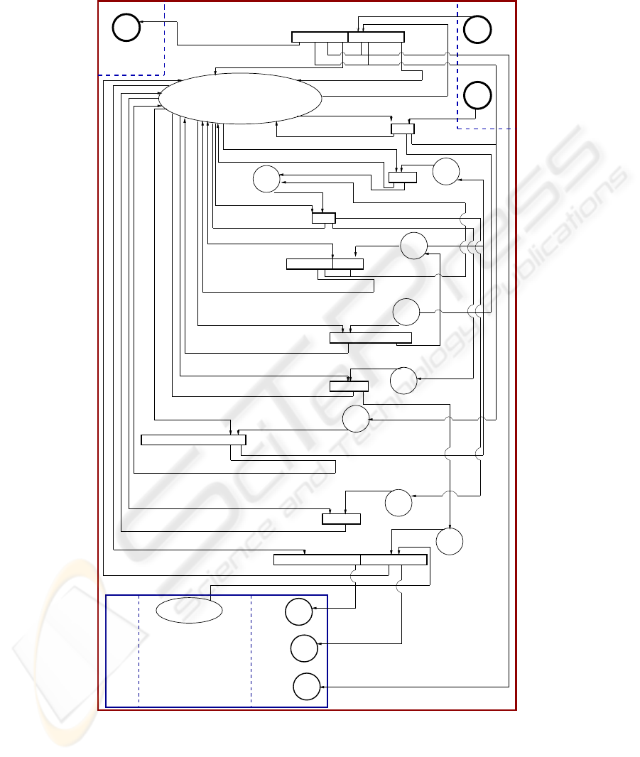
For instance, by respecting the aforementioned translating steps, the CO-NET as-
sociated with the HTS template is depicted in figure 3. In this net, besides the state
place OBJ
HTS that contains all HTS state instances, with each message generator
a corresponding place is associated. Places reflecting imported / exported messages
are represented in bold. For the Job component declared as a subcomponent (in the
HTS TROLL text), we have just represented the places of imported messages namely
RCV
ApvD, RCV ApvO, ADD JOB and the exported attributes Type of job (i.e. OFFER
or DEMAND). Each transition reflect the effect of messages on the just concerned state
parts. The transition RCV
JOB, where the message Receive J(J,M,H) (with J, M, H de-
notes respectively job identity, machine identity and HTS identity) enters into with state
part hH|StateH : Ready, J ob : Jb, P artner Rq : Ri. This means that according to the
HTS state diagram, the HTS state of H should be Ready and their is some (list of) jobs
Jb. The effect of such contact depending on whether a partner is requested or not (i.e.
the variable R is true or not) is as follows. In the first case (i.e. Partner
Rq = True) the
invoked part of HTS object state is modified to hH|StateH : Calculated, Job : J b :
J, P artner
Rq : Ri with a simultaneous sending of the messages Request P(J,H,M),
Add Job (to the job subcomponent) and Calc Offer(J,H). In the second case, the HTS
object part of state is modified to hH|StateH : Contact
J, Job : Jb : J, P artner Rq : Ri
with a simultaneous sending of the messages Add Job and Calc Offer(J,H).
70
Calc_Offr(H,C)
Receive_J(J,M,H)
The HTS Component as a Co-Net
<H | StateH: Approved, Ntm : N, Nlm : L, Job : J.Jb>
Calc_O(Jb,H)
<H | Ntm:T,NLm:L,offr:F>
Requst_P(J,H,M)
<H | Ntm:T,NLm:L,offr:F.[H,C]>
<H | StateH : Contacted ,Answ: S>
Recv_O(*,0)
Calc_O(J,H)
ADD_J(J)
<H | StateH: Sended, Ntm : N, Nlm : L, Job : Jb>
The Job Subcomponent
Send_abd(H)
<H | StateH: Snd, Exist_O: B, Ntm:T,RTm: R, NLm:L>
<H | StateH: Calculated, My_O : My, Offr : F, Answ : S, Job : Jb.J>
<H | StateH: Calculated, Part_Rq:Q,Rtm:R,RLm:L,Part:P, Offr : F.[H,C]>
<H | StateH: Recv_A, Part_Rq:Q,Rtm:R,RLm:L,Part:P, Offr : F>
Wait_O(*,0)
<H | StateH: Rcv_A, Rtm : R, RLm : M, Answ: S>
<H | StateH: Approval, My_Offr : My>
<H | StateH: Sended, My_Ofr : My>
<H | StateH: Calculated, Rtm : R, RLm : M, Answ: S>
Send_Of(H)
<H | StateH: Calculated, Exist-O:True, Ntm:N,NLm:L,My-Cst:C>
Wait_Of(*,0)
Recv_O(H,C)
<H | StateH : Ready,Answ: S.[M,C]>
<H | StateH: Sended, Exist-O:True, Ntm:N,NLm:L,My-Cst:C>
Receive(H,M,C)
Abort(H,Jb)
OBJ_HTS
<H | StateH : Calc, Job : Jb.J,Parner_Rq:R>
<H | StateH: Contact, Exist_O: B, Ntm:T,RTm: R, NLm:L>
Abort(H,J)
Send_abr(H)
Send_abr(H)
Recv_Of(*,C)
Recv_Of(*,C)
Send_Of(H)
Wait-Ans(H)
<H | StateH : Ready, Job : Jb,Parnter_Rq:R>
<H1 | StateM: Ready, Ntm:r1,Rtm:n1,Ans:S1,Offr:o1,.....>
<J | Type : Tp>
Rcv_AprO(J,H)
Rcv_AprD(J,H)
<H | StateH : Contact,Job:Jb.J,Partner_Rq:R>
Send_aprv(H,J)
Send_aprv(H,J)
Wait-Ans(H)
<H | StateH: Ready, My_O : nil, Offr : nil, Answ : nil, Job : Jb>
(N > L) and (Tp = DEMAND) (N > L) and (Tp = OFFER)
The Exported Messages
The imported Messsages
. . ..
Add_J(...)
. . ..
RCV_JOB
REQUST_P
(Machine.)
(Macghine)
. . ..
My > Best_O
The Imported Messages
The Exported Messages
B = True or T > L
Receive_J(..)
. . ..
Rcv_AprO(.)
Rcv_AprD..)
Receive_J(..)
Snd_abr(..)
. . ..
SND-ABR
. . ..
. . ..
The Internal Behaviour
. . ..
. . ..
Requset_P()
RCV_JOB
RCV_PR
SND_ABR
WAIT_ANS
WAIT_OFR
CALC_OFR
ABORT
SND_APRV
<J1 | Type : T1,..>
. . ..
OBS_JOB
RCV-AprD
RCV-ApvO
ADD_J
R =True
approval(..)
T < L
APPROVAL
R < L
RCV-PART
Rcv_of(..)
. . ..
RCV_OFFR
SND_OFFR
Snd_offr(..)
. . ..
WAIT_ANSW
N <= L
SND_OFR
. . ..
CALC_O
My = Best
RCV_OFR
. . ..
Calc_O(..)
abort(..)
ABORT
. . ..
(R <= L) or cnt(P) = max_part (Q=true) or
. . ..
wait_offr(..)
WAIT_OFFR
cnt(S)= max and R <= M
wait_ans(..)
Else
True
Fig.3. The HTS CO-NETS Specification.
71

6 CO-NETS Specification Certification
The CO-NETS approach with its rewriting logic based operational semantics allows
not only for graphical visual animation of the intra-component computation and the
inter-component cooperation but also for deriving symbolic proofs using the associ-
ated rewrite theory [4]. While validating the modelled component-based information
systems, a strict explicit separation of concerns is adopted where:
– The behavioral certification of a given component (as a class in the simple case)
by concurrent rewriting and simultaneous graphical animation from an initial com-
ponent state is completely independent from any other component. The efficiency
intervenes here by the limited number of manipulated transition rewriting rules
compared to the case where the whole system (i.e. when following a usual UML
monolithic process where all classes at stake at once) is analyzed.
– The certification of the communication and the effect of inter-component interac-
tions on the whole system is also achieved independently, by taking into account
only the interface of the concerned components.
Example 2. By applying the general forms of rewrite rules, it is not difficult to generate
the rules governing the behaviour of both HTS and Machine components as well as
those of their interactions. Hereafter, due to space limitation we just illustrate it through
two rewrite rules of the HTS component.
RECV
JOB
2
: (RCV JOB, Receive J(J, M, H)) ⊗ (OBJ HT S, hH|StateH :
Ready, J ob : Jb, P artner Rq : Ri) ⇒ if (R = T rue) then (OBJ HT S, hH|StateH :
Calculated, Job : Jb, P artner Rq :
Ri) ⊗ (REQUEST
P, Request P (J, H, M)) ⊗ (ADD J OB, Add job(J )) ⊗
(CALC OF F R, Calc Of (J, H)) else (OBJ HT S, hH|StateH : Contacted, Job :
Jb, P artner
Rq : Ri) ⊗ (ADD JOB, Add job(J)) ⊗ (CALC OF F R, Calc Of(J, H))
RCV
PAR: (RCV P ART, Receive P (J, M, C)) ⊗ (OBJ HT S, hH|StateH :
Contact, Answ : Si) ⇒ (OBJ HT S, hH|StateH : Ready, Answ :
S.[M, C]i) ⊗ (W AIT ANS, W ait answ(H)) ⊗ (CALC OF F R, Calc O(Jb, H))
7 Conclusions
In this paper, we presented a stepwise proposal for semi-formally modelling and for-
mally specifying and validating advanced distributed information systems. The pro-
posal starts with widely accepted and practitioner-oriented UML methodology. More
precisely, we model the information through its class- communication and statecharts
diagrams plus OCL-pre- and post-conditions. For sake of global coherent view of these
different diagrams, we propose to incrementally derive CO-NETS components, where
intra- computation is explicitly separated from inter-interactions and where rapid- pro-
totyping are possible with graphical animation and rewriting computations. In order to
72

emphasize the practicability and the capabilities for developing even complex infor-
mation systems, we have applied the proposed methodology to a significant part of a
realistic case study dealing the production cell problem.
Nevertheless, after achieving this very important and first steps towards develop-
ing advanced information systems, we are conscious that much a work remain ahead.
First, we plan a deeper study for an appropriate and efficient translation of the generated
rewriting rules into JAVA programs. Second, we are working for developing a complete
software environment for the CO-NETS framework, including particularly an editor /
simulator and relate it with current UML environment such as Rational and Posedion.
For the rewriting sides we are adapting the current implementation of the MAUDE lan-
guage. Last but not least, for coping with the runtime evolution due to frequent changes
we are working on an appropriate reflective extension of the CO-NETS approach.
Acknowledgements
The authors want to warmly thank the three referees for their constructive comments,
that significantly helped improving the present final version.
References
1. Jungclaus, R., Wieringa, R.J., Hartel, P., Saake, G., Hartmann, T.: Combining TROLL with
the Object Modeling Technique. In Wolfinger, B., ed.: Innovationen bei Rechen- und Kom-
munikationssystemen. GI-Fachgespr
¨
ach FG 1: Integration von semi-formalen und formalen
Methoden f
¨
ur die Spezifikation von Software. Informatik aktuell, Springer (1994) 35–42
2. Wirsing, M., Knapp, A.: A Formal Approach to Object-Oriented Software Engineering.
ENTCS 4 (1996)
3. Booch, G., Jacobson, I., Rumbaugh, J., eds.: Unified Modeling Language, Notation Guide,
Version 1.0. Addison-Wesley (1998)
4. Aoumeur, N., Saake, G.: A Component-Based Petri Net Model for Specifying and Validating
Cooperative Information Systems. Data and Knowledge Engineering 42 (2002) 143–187
5. Meseguer, J.: Solving the Inheritance Anomaly in Concurrent Object-Oriented Programming.
In: ECOOP’93 - Object-Oriented Programming. Volume 707 of Lecture Notes in Computer
Science., Springer (1993) 220–246
73
