
SUPPORTING DESIGN PATTERNS IN GRAPH
REWRITING-BASED MODEL TRANSFORMATION
László Lengyel, Tihamér Levendovszky, Tamás Mészáros and Hassan Charaf
Budapest University of Technology and Economics, Goldmann György tér 3, 1111 Budapest, Hungary
Keywords: Model Transformation, Graph Rewriting, Design Patterns, Rewriting Rule Patterns.
Abstract: Model transformations appear in many, different situations in a model-based development process. A few
representative examples are as follows: refining the design to implementation, aspect weaving, analysis, and
verification. In object-oriented software design, design patterns describe simple and elegant solutions to
specific problems. Similarly, design pattern should be identified in model transformations as well to support
the frequently appearing problems. This paper introduces the design pattern support of a modelling and
model transformation framework (Visual Modeling and Transformation System). Furthermore, we discuss
two model-based development related design patterns.
1 INTRODUCTION
Specifying systems in a higher abstraction level
helps understanding, developing and maintaining
software. A higher abstraction level can be achieved
by software models and their model transformation.
Model compilers provide a solution for automated
source code generation from software models and
mechanisms for software maintenance (Sztipanovits
& Karsai, 1997) (Sztipanovits & Karsai, 2002).
Modelling software systems helps conceiving
and visualising the actual design, but real
automation needs efficient model processing
facilities, namely, model compilers.
A model compiler is a tool that automatically
composes a model from a set of sub-models and an
architectural description of the arrangement of sub-
models (Butts et al, 2001). The output of a model
compiler can be not only a model but source code as
well.
Model-driven development approaches (such as
Model-Integrated Computing (MIC) (Sprinkle,
2004) (Sztipanovits & Karsai, 1997) and OMG’s
Model-Driven Architecture (MDA) (OMG MDA,
2003)) emphasize the use of models at all stages of
system development. They have placed model-based
approaches to software development into focus.
Graph transformation is a widely used technique
for model transformations. Especially, visual model
transformations can be expressed by graph
transformations, since graphs are well-suited to
describe the underlying structures of models.
Graph rewriting (Rozenberg, 1997) is a powerful
tool for graph transformations with strong
mathematical background. The atoms of graph
transformation are rewriting rules, each rewriting
rule consists of a left-hand side graph (LHS) and
right-hand side graph (RHS). Applying a graph
rewriting rule means finding an isomorphic
occurrence (match) of the LHS in the graph the rule
being applied to (host graph), and replacing this
subgraph with RHS. Replacing means removing
elements which are in the LHS but not in the RHS,
and gluing elements which are in the RHS but not in
the LHS.
In graph rewriting-based model transformation,
there are several recurring problems that should be
solved again and again in the context of different
transformations or different environments. In
(Agrawal et al, 2004), a few reusable idioms and
patterns are provided in the context of graph
transformation languages. A pattern is a reusable
entity, which describes a frequent design or
implementation problem, and gives a general but
customizable solution to it. Illustrative examples are
object-oriented design patterns defined by UML
diagrams (Gamma et al, 1995). The current work
discusses model transformation design patterns from
the point of metamodel-based model transformation
view. Furthermore, we introduce our tool support
25
Lengyel L., Levendovszky T., Mészáros T. and Charaf H. (2007).
SUPPORTING DESIGN PATTERNS IN GRAPH REWRITING-BASED MODEL TRANSFORMATION.
In Proceedings of the Second International Conference on Evaluation of Novel Approaches to Software Engineering , pages 25-32
DOI: 10.5220/0002585100250032
Copyright
c
SciTePress

that provides the application of the patterns in
transformation definitions.
The presented model transformation design
patterns require neither unusual transformation
language features nor unusual sophisticated
solutions. All can be implemented in standard graph
rewriting-based transformation languages. In
general, implementing patterns might take a little
more work than ad hoc solutions, but the extra effort
returns in increased flexibility and reusability.
The rest of the paper is organized as follows.
Section 2, as background information, introduces
our modelling and model transformation framework:
Visual Modeling and Transformation System
(VMTS). Section 3 presents the design pattern and
transformation wizard tool support of VMTS.
Section 4 dicusses the metamodel-based model
transformation design patterns. Section 5 provides
the related work information. Finally, conclusions
are given.
2 VISUAL MODELING AND
TRANSFORMATION SYSTEM
As background information, this section introduces
our implemented metamodeling and model
transformation framework Visual Modeling and
Transformation System (VMTS) (VMTS, 2003).
Visual Modeling and Transformation System
supports editing models according to their
metamodels, and allows specifying constraints
written in Object Constraint Language (OCL) (OMG
OCL, 2006). Models are formalized as directed,
labelled graphs. VMTS uses a simplified class
diagram for its root metamodel (”visual
vocabulary”). Also, VMTS is a model
transformation system, which transforms models
using graph rewriting techniques. Moreover, the tool
facilitates the verification of the constraints specified
in the transformation rule during the model
transformation process.
In VMTS, LHS and RHS of the transformation
rules are built from metamodel elements. This
means that an instantiation of LHS must be found in
the input graph instead of the isomorphic subgraph
of LHS.
Rewriting rules can be made more relevant to
software engineering models if the metamodel-based
specification of the transformations allows assigning
OCL constraints to the individual transformation
rules. This technique facilitates a natural
representation for multiplicities, multi-objects and
assignments of OCL constraints to the rules with a
syntax close to the UML notation.
Figure 1: Example transformation rule: ClassToTable.
An example transformation rule that generates
database tables from UML classes is depicted in Fig.
1. Constraints propagated to the transformation rule
nodes are also presented: Cons_C1, Cons_C2,
Cons_H1, Cons_T1, and Cons_T2. With the help of
these constraints we can require certain properties
from the transformation rule, and we can make them
validated (Lengyel, 2006).
context Class inv Cons_C1:
not self.abstract
The constraint Cons_C1 is assigned to the
pattern rule node Class in LHS of the rule
CreateTable. This link forms a precondition for the
rule, it requires the rule to process only non-abstract
classes.
context Table inv Cons_T1:
self.columns->exists(c | c.datatype =
'int' and c.is_primary_key)
The constraint Cons_T1 is a postcondition of the
rule CreateTable, it is assigned to the rule node
Table. This constraint requires the rule that all
created table has a primary key of int type.
context Atom inv Cons_H1:
self.class.attribute->forAll
(self.table.column->
exists(c | (c.columnName =
class.attribute.name))
The constraint Cons_H1 is linked to the rule
node TableHelperNode, it requires that each class
attribute should have a created column with the
same name in the resultant table.
The constraints assigned to the transformation
rule guarantee our requirements. After a successful
ENASE 2007 - International Conference on Evaluation on Novel Approaches to Software Engineering
26
rule execution, the conditions hold and the output is
valid, which cannot be achieved without constraints.
VMTS facilitates a refined description of the
transformation rules. When the transformation is
performed, the changes are specified by the RHS
and internal causality relationships defined between
the LHS and the RHS elements of a transformation
rule. Internal causalities can express the
modification or removal of an LHS element, and the
creation of an RHS element. Imperative OCL (OMG
QVT, 2005) or XSLT scripts can access to the
attributes of the objects matched to the LHS
elements, and produce a set of attributes for the RHS
element to which the causality points.
Classical graph grammars apply any production
that is feasible. This technique is appropriate for
generating and matching languages but model
transformations often need to follow an algorithm
that requires a stricter control over the execution
sequence of the rules, with the additional benefit of
making the implementation more efficient.
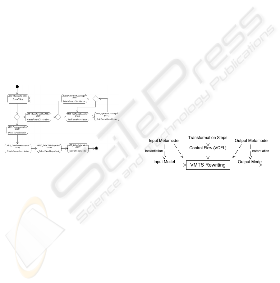
Figure 2: Example transformation (VCFL model):
ClassToRDBMS.
The VMTS approach is a visual approach, thus,
it also uses graphical notation for control flow:
stereotyped UML activity diagrams. VMTS Visual
Control Flow Language (VCFL) is a visual language
for controlled graph rewriting and transformation,
which supports the following constructs: sequencing
transformation rules, branching with OCL
constraints, hierarchical rules, parallel execution of
the rules, and iteration. An example VMTS
transformation, a VCFL model, is presented in Fig.
2.
VMTS transformation rules have two specific
properties: Exhaustive and MultipleMatch. An
exhaustive transformation rule is executed
repeatedly, as long as LHS of the rule can be
matched to the input model. The MultipleMatch
property of a rule allows that the matching process
finds not only one but all occurrences of LHS in the
input model, and the replacement is executed on all
the found places.
The interface of the transformation rules allows
the output of one rule to be the input of another rule
(parameter passing), in a dataflow-like manner. In
VCFL, this construction is referred to as external
causality. An external causality creates a linkage
between a node contained by RHS of the rule i and a
node contained by LHS of the rule i+1. Since rule i
provides partial match to rule i+1, this feature
accelerates the matching process and reduces the
complexity.
VMTS supports validated model transformation,
constraint management and control flow definition.
The environment has standalone algorithms and
other solutions that make them efficient. Moreover,
VMTS has a unique, aspect-oriented technique-
based constraint management (Lengyel, 2006). The
constraint-driven branching mechanism of the
VMTS is unique in the sense that the decision is
made not only based on the actual state of the input
model but using system variables
(SystemLastRuleSucceed) as well. If a
transformation rule fails, and the next element in the
control flow is a decision object, then it can provide
the next branch based on these variables. Fig. 3
outlines the principles of VMTS metamodel-based
model transformation.
Figure 3: Principles of VMTS metamodel-based model
transformation.
3 DESIGN PATTERN AND
TRANSFORMATION WIZARD
SUPPORT IN VMTS
This section shortly introduces domain-specific
design patterns and the Visual Model Processor
(VMP) wizard support of VMTS.
3.1 VMTS Design Pattern Support
Creating domain-specific model patterns and reusing
them in different domain-specific models offer great
perspectives for rapid application development and
keep reliability at a high-level as well. VMTS
SUPPORTING DESIGN PATTERNS IN GRAPH REWRITING-BASED MODEL TRANSFORMATION
27

provides a tool support to create general but
customizable model patterns.
Patterns are defined as general models based on
their metamodels. Of course, patterns can be applied
for models, which have the same metamodel as the
patterns.
There was a natural need for the capability of
organising them into pattern repositories and
attaching some meta-information to the patterns as
well. A domain-specific model has been created,
whose instance model elements represent a reference
to pattern models. The instance models behave as
pattern repositories as they can contain numerous
references to design pattern models.
The modelling framework of the VMTS
facilitates to browse patterns and apply them to the
actual model. Furthermore, the customization of
pattern element attributes is also supported.
The VMTS Rule Editor and Control Flow plug-
ins are implemented as domain-specific models:
they are defined with their metamodels and plug-in-
dependent visualisation is added to them (VMTS,
2003). Therefore, the VMTS design pattern support
can be applied both for transformation rules and
control flow models.
3.2 VMTS Visual Model Processor
Wizard
VMTS provides a tool support for automatic Visual
Model Processor (VMP) generation. The
transformation generated by VMTS VMP Wizard
contains a control flow (VCFL) model and rewriting
rules.
VMTS VMP Wizard provides the possibility (i)
to select from the “hello world transformations”:
such as UML class diagram to source code
(ClasToCode), or (ii) to customise the
transformation: e.g. select the metamodels of the
source and target models, or to select the option to
generate source code.
The mechanisms used by the framework to
generate the transformation based on the selected
options are the XML-based import and the design
pattern support (Section 3.1) of VMTS. The example
transformations are exported as XML files and can
be imported during the VMP generation.
Furthermore, the import and the design pattern
support is combined in certain cases: the control
flow model is imported from XML, but the rewriting
rules are inserted via the design pattern support
mechanisms.
4 DESIGN PATTERNS IN MODEL
TRANSFORMATION
Design patterns presented in this section are based
on the transformation “class model to relational
database management system (RDBMS) model”
(also referred to as object-relational mapping). The
control flow model of the transformation is
presented in Fig. 2. The validated solution of the
case study can be found in (Lengyel, 2006) and
(Lengyel et al, 2006).
We have divided the model transformation-
related design patterns into the following groups:
full rewriting rules, partial rewriting rules, and
control flow patterns (a pattern containing more
rewriting rules).
Based on the well-estabilished method used to
define design patterns in the object-oriented world,
we provide the same structure for the description of
metamodel-based model transformation patterns: (i)
Motivation: a problem, the pattern is intended to
solve. (ii) Applicability: the general class of
problems in which the design pattern can be applied.
(iii) Structure: the abstract graphical representation
of the pattern. (iv) Consequences: the trade-offs and
results of using the pattern (advantages and
disadvantages). (v) Known uses: examples of the
pattern found in transformations. (vi) Variations: the
known solutions of other approaches, and the
important differences.
Section 4.1 is devoted to the dicussion of a rewriting
rule pattern, which presents a rule part. Section 4.2
presents a pattern that contains not only a single rule
or rule part, but several rewriting rules and a control
flow pattern as well.
4.1 The Helper Construct Pattern
Motivation. In transformation ClassToRDBMS, the
first rule, ClassToTable (Fig. 1), creates database
tables for all non-abstract classes. A generated table
contains columns for each attribute in its origin
class. At this point the tables are not complete,
because not only the actual class but its parent
classes should also be taken into account. In general,
an input model contains several classes. Later in the
transformation we need to add further columns to
the tables based on the corresponding parent classes.
Therefore we need the information that relates the
original class and its generated table. This can be
solved with helper constructs that can temporarily
relate model elements, even if they are in different
models (with different metamodels).
ENASE 2007 - International Conference on Evaluation on Novel Approaches to Software Engineering
28
Applicability. Helper constructs support to
temporarily releate model elements that cannot be
releated based on their metamodel. The helper
construct is created by a model transformation, it can
be used during the actual transformation, but it
should be removed till the end of the transformation.
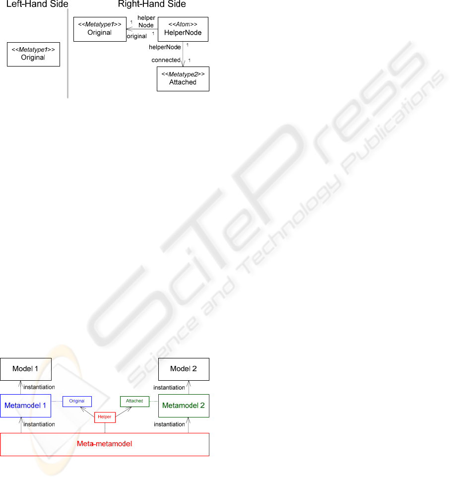
Figure 4: Sructure of the Helper Construct Pattern.
Structure. The structure of the pattern is presented
in Fig. 4. Recall that metamodel-based rewriting
rules are built from metamodel elements. Often, the
helper construct must connect elements from
different models. In the current solution the
metatypes of the helper constructs do not belong to
any of the actually used metamodels. They are based
on the hard-wired meta-metamodel that provides
basic contructs for metamodel definitions: Atom, and
different relations: SystemInheritance,
SystemContainment, and SystemRelationship
(VMTS, 2003). Fig. 5 presents that metamodel-
based rewriting rules are on the same level as
metamodels. Furthermore, the rule node Original
has metatype from Metamodel 1, rule node Atteched
has metatype from Metamodel 2, and the metatype
of the helper constuct is from Meta-metamodel. Fig.
5 introduces the instantiation hiearchy applied in a
metamodeling tool.
Figure 5: The the instantiation hiearchy of a metamodeling
tool.
Consequences. Optional temporary relations can be
supported between optional model elements, even
they are from different models. Furthermore,
optional attributes can be assigned to the temporary
relations that can make them more sophisticated.
Helper construct elements have different metatypes
than input and output model elements, therefore, it
can be automatically checked not to leave helper
construct in processed models.
This pattern provides the basis for the automatic
trace generation during the model transformation. In
VMTS, trace elements are generated based on the
internal causalities using the structure of the current
pattern.
Known uses. (i) In the transformation ClassToTable
temporary relaions between: (a) Class and Table
elements, (b) Class elements, which are devoted to
support the creation of the transitive closure upwards
in the inheritance hierarchy, and (c) Class elements,
which are used to created foreign key relations. (ii)
In transformation ClassToCode between Package
and Namespace elements.
Variations. The following environments have been
examined how they support helper constructions:
AGG (Taentzer, 2003) is an integrated development
tool for typed attributed graph transformation,
AToM
3
(Lara et al, 2004), which supports regular
graph grammars and triple graph grammars, the
VIATRA (Varró and Pataricza, 2003) approach that
combines the rule and pattern-based paradigm of
graph transformation and abstract state machines
(ASM), the GReAT (Karsai et al, 2003) framework,
which is a transformation system for domain-
specific languages, and FUJABA (Köhler et al,
2000) that extends UML, story driven modelling and
graph transformation. All of them provides slutions
that support the runtime creation of the helper
constructs. In case of AGG and AToM
3
helper types
are added to the metamodels and then they can be
used in model transformation rules (Taentzer et al,
2005).
4.2 The Optimized Transitive Closure
Pattern
Motivation. Recall that in transformation
ClassToTable the columns of the generated table
should be created not only based on the actual class,
but on its parent classes as well. Therefore, we
should support the creation of the transitive closure
upwards in the inheritance hierarchy. Furthermore,
the relations between the tables should be created
not only based on the relations of the actual class,
but based on the relations of the parent classes as
well. Furthermore, using temporary associations the
actual class and the neighbours of the parent classes
should be related.
SUPPORTING DESIGN PATTERNS IN GRAPH REWRITING-BASED MODEL TRANSFORMATION
29
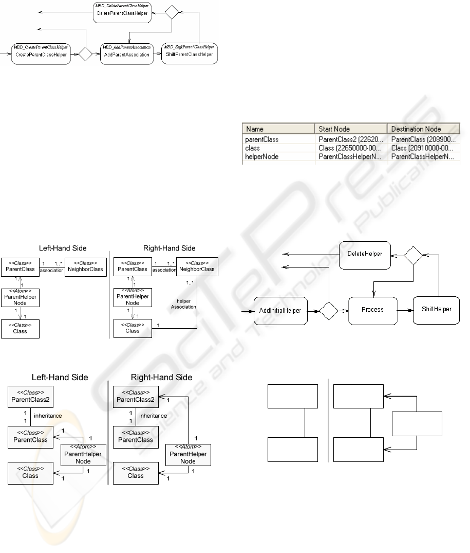
The control flow pattern of the transitive closure
traversing inheritance hierarchy is depicted in Fig. 6.
Figure 6: The control flow model of the inheritance
transitive closure.
Rule CreateParentClassHelper inserts a helper
construct between a class (provided with the help of
an external causality) and its base class if any. If the
rule was successful, there exists a base class, then
the transformation continues with rule
AddParentAssociation (Fig. 7). This rule creates a
temporary association that links the child class to the
neighbours of the parent class. These associations
facilitate that the rule ProcessAssociations (Fig. 2.)
processes not only the direct associations of a class,
but the association of its parents as well.
Figure 7: Rewriting rule AddParentAssociation.
Figure 8: Rewriting rule ShiftParentClassHelper.
The transformation should traverse the whole
inheritance hierarchy. The rule
ShiftParentClassHelper (Fig. 8) removes the
original helper construct, and adds a new one which
links the child class to the parent of the parent class.
If the rule ShiftParentClassHelper finishes
successfully (there exits parent on the next
inheritance level), then the transformation continues
with rule AddParentAssociation. These two rules
form a loop that presents the core of the transitive
closure pattern. The external causalities defined
between the rules ShiftParentClassHelper and
AddParentAssociation are depicted in Fig. 9. The
key external causality is the causality parentClass
that links the node ParentClass2 from RHS of the
rule ShiftParentClassHelper and ParentClass from
the LHS of the rule AddParentAssociation. This
external causality supports to step between the
inheritance levels. Finally, rule
DeleteParentClassHelper removes the helper
construct.
Figure 9: External causalities between rules
ShiftParentClassHelper and AddParentAssociation.
Applicability. In case of transformations where the
transitive closure should be calculated.
Figure 10: The control flow pattern of the transitive
closure.
Left-Hand Side Right-Hand Side
<<Metatype>>
Neighbor
<<Metatype>>
Source
neighborhood
1
<<Metatype>>
Neighbor
<<Atom>>
HelperNode
<<Metatype>>
Source
1
1
1
neighborhood
Figure 11: Rewriting rule AddInitialHelper.
Structure. The abstract control flow model of the
optimized transitive closure is depicted in Fig. 10.
The rule AddInitialHelper (Fig. 11) initializes the
input with a helper construct: connects the rule node
Source with its direct special type neighbour. If the
rule node has the adjacent rule node of required
type, the rule can be executed successfully and the
next rule will be the Process. The rule Process
performs the required modifications based on the
rule nodes Source and its actual Neighbor, which are
ENASE 2007 - International Conference on Evaluation on Novel Approaches to Software Engineering
30
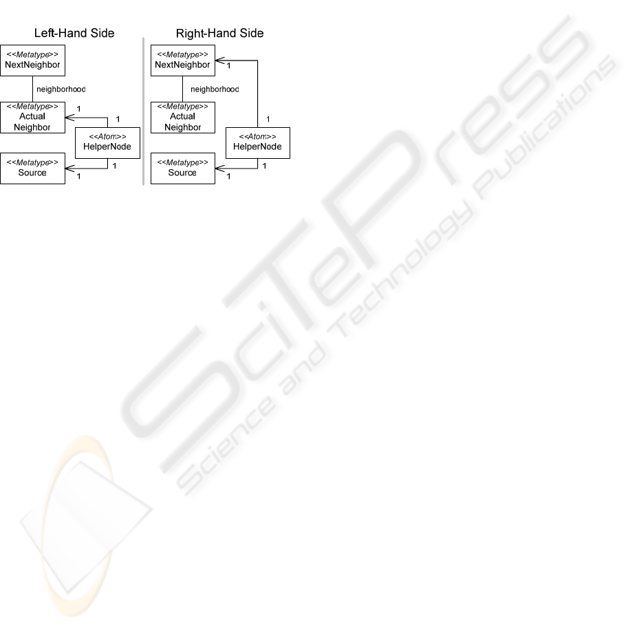
connected with a helper construct. The rule
ShiftHelper (Fig. 12) is responsible to shift the
helper construct from the actual neighbour to its next
neighbour. There is a key external causality in the
loop formed by the rules ShiftHelper and Process,
which connects the rule node NextNeighbor from
RHS of the rule ShiftHelper to the rule node
ActualNeighbor from LHS of the rule Process. This
external causality facilitates that each loop iteration
to expand the visited neighbour chain. Finally, rule
DeleteHelper removes the helper construct.
Figure 12: Rewriting rule ShiftHelper.
Consequences. The presented construct is not a
usual transitive closure pattern, rather an optimized
transitive closure pattern. Helper constructs are not
left between the traversed classes, but they are
moved up during the process and removed at the
end.
Often, algorithms implemented by model
transformations require the repetition of a process
within a transformation. The presented pattern
provides solution for iterative and recursive
behaviour. The key concepts of these constructs are
external causalities that facilitates to a rule provide
part matches (input or parameters) to another rules.
Known uses. (i) In the transformations
ClassToTable and ClassToCode to traverse the
inheritance hierarchy. (ii) In transformations
FlattenStatechart and StatechartToSourceCode to
traverse the statechart hierarchy.
Variations. In AGG, transitive closure is calculated
by recursive rule application. AGG do not define
additional control structures for the rule execution,
but coordinate them by the definition of layers. Each
rule is assigned to a certain layer. Starting with layer
0, the rules of one layer are applied as long as
possible, and then the next layer is executed. AToM
3
and AGG use negative application conditions
(NACs) to forbid the rule execution in certain cases.
In AToM
3
, the transitive closure is calculated by
iterative rule application (Taentzer et al, 2005).
The control structures in VIATRA are
implemented with abstract state machine (ASM)
statements. Transitive closure is calculated by the
forall ASM control structure.
In (Agrawal et al, 2004), the transitive closure
solution of GReAT is provided, which works for
directed acyclic graphs. The solution is based on the
iterative rule application. Comparing this solution
with the currently presented optimized transitive
closure pattern we can state that GReAT’s solution
leave the helper constructs in the processed model.
Contrary to this, VMTS adds the helper construct to
the model only for the execution of the useful
procedure.
FUJABA uses the * operator to compute the
transitive closure of a basic path expression (a dotted
list of edge labels).
5 RELATED WORK
Object-oriented design patterns (Gamma et al, 1995)
make it easier to reuse successful designs and
architectures in source code level. Defining proven
methods as design patterns makes them more
accessible to developers of new systems. Design
patterns help choosing design alternatives that make
a system reusable. Furthermore, design patterns can
improve the documentation and maintenance of
existing systems by providing an explicit
specification of class and object interactions and
their underlying intent.
In (Agrawal et al, 2004), a graph transformations
language, GReAT is presented, and it is shown how
typical design problems that arise in the context of
model transformations can be solved using the
constructs of GReAT. The presented patterns are
intended to serve as the starting point for a more
complete collection. Unfortunately, the presented
tool does not have direct support for patterns.
Many approaches have been introduced in the
field of graph grammars and transformations to
capture graph domains; for instance, GReAT (Karsai
et al, 2003), PROGRES (Schürr, 1999), FUJABA
(Köhler et al, 2000), VIATRA (Varró and Pataricza,
2003), AToM
3
(Lara et al, 2004) and Attributed
Graph Grammar (Taentzer, 2003). These approaches
are specific to the particular system, and each of
them has some features that others do not offer. The
main features of these approaches are already
discussed in the Variations sections of the presented
design patterns.
At the time of the writing, we have no
knowledge about that any of the modeling or model
SUPPORTING DESIGN PATTERNS IN GRAPH REWRITING-BASED MODEL TRANSFORMATION
31

transformation environments (except for VMTS)
provide tool support for transformation patterns.
6 CONCLUSIONS
This paper has introduced the design pattern and
transformation wizard tool support of Visual
Modeling and Transformation System, and
discussed two metamodel-based model
transformation related design patterns.
VMTS supports rewriting rule patterns in model-
based development. Patterns are available on
different levels: parts of the whole transformation
rules, whole transformation rules, and several
transformation rules can reperesent a pattern as well.
Patterns can contain constraints assigned to the rule
nodes, and internal causalities that describe the
changes that should be executed during the rule
firing.
Model transformation-related desing patterns and
the presented transformation wizard support make
the metamodel-based model transformatioin easier,
more efficient and rapid. Furthermore, design
patterns with adequate constraints attached to them
can support the validated model transformation as
well.
ACKNOWLEDGEMENTS
The fund of “Mobile Innovation Centre” has
supported, in part, the activities described in this
paper.
REFERENCES
Agrawal, A., Vizhanyo, A., Kalmar, Z., Shi, F.,
Narayanan, A., Karsai, G., 2004. Reusable Idioms and
Patterns in Graph Transformation Languages, 2nd Int.
Conference on Graph Transformation, Rome, Italy.
Butts, K., Bostic, D., Chutinan, A., Cook, J., Milam, B.,
Wang, Y., 2001. Usage scenarios for an Automated
Model Compiler, EMSOFT 2001, pp 66–79.
Gamma, E., Helm, R., Johnson, R., Vlissides, J., 1995.
Design Patterns: Elements of Reusable Object-
Oriented Software, Addison-Wesley Professional
Computing Series.
Karsai, G., Agrawal, A., Shi, F., Sprinkle, J, 2003. On the
Use of Graph Transformation in the Formal
Specification of Model Interpreters, Journal of
Universal Computer Science, Special issue on Formal
Specification of CBS.
Köhler, H. J., Nickel, U., A. Niere, J., Zündorf, A., 2000.
Integrating UML Diagrams for Production Control
Systems, 22nd Int. Conf. on Software Engineering
(ICSE), Limerick Ireland, ACM Press, pp. 241-251.
Lara, J., Vangheluwe, H., Alfonseca, M., 2004. Meta-
modelling and graph grammars for multi-paradigm
modelling in AToM, SoSyM, August, 3(3):194-209.
Lengyel, L., Levendovszky, T., Charaf, H., 2005. Graph
Transformation and Constraint Validation-Driven User
Interface Handler Code, MicroCAD, March 10-11,
2005, Miskolc, pp. 267-272.
Lengyel, L., 2006. Online Validation of Visual Model
Transformations, PhD thesis, Budapest University of
Technology and Economics, Department of
Automation and Applied Informatics.
Lengyel, L., Levendovszky, T., Mezei, G., Charaf, H.,
2006. Model-Based Development with Strictly
Controlled Model Transformation, In The 2nd Int.
Workshop on Model-Driven Enterprise Information
Systems, MDEIS 2006, Cyprus, pp. 39–48.
OMG MDA Guide Version 1.0.1, 2003. Document
number: omg/2003-06-01,
www.omg.org/docs/omg/03-06-01.pdf
OMG OCL Specification, Version 2.0, 2006.
http://www.omg.org/
OMG QVT, 2005. Meta Object Facility 2.0
Query/Views/Transformation Specification,
http://www.omg.org/cgi-bin/apps/doc?ad/05-03-02.pdf
OMG UML Specification, Version 2.1.1, 2007.
http://www.uml.org/
Quantum Framework (qF) Web Site,
http://www.quantum-leaps.com/qf.htm
Rozenberg, G. (ed.) 1997, Handbook on Graph Grammars
and Computing by Graph Transformation:
Foundations, Vol.1 World Scientific, Singapore.
Schürr, A., Winter, A.J., Zündorf, A., 1999. The
PROGRES approach: Language and environment.
Sprinkle, J., 2004. Model-Integrated Computing, IEEE
Potentials, 23(1):28-30, 2004.
Sztipanovits, J., Karsai, G., 1997. Model-Integrated
Computing, IEEE Computer, pp. 110-112.
Sztipanovits, J., Karsai, G., 2002, Generative
Programming for Embedded Systems, LNCS 2487, pp.
32-49.
Taentzer, G., 2003. AGG: A Graph Transformation
Environment for System Modeling and Validation. In
Proc. Tool Exihibition at Formal Methods 2003.
Taentzer, G., Ehrig, K., Guerra, E., de Lara, J., Lengyel,
L., Levendovszky, T., Prange, U., Varro D., Varro-
Gyapay, Sz., 2005. Model Transformation by Graph
Transformation: A Comparative Study, ACM/IEEE
8th Int. Conference on Model Driven Engineering
Languages and Systems, Montego Bay, Jamaica.
Thai T. and Lam H., 2003. .NET Framework Essentials,
O’Reilly.
Varró, D. and Pataricza, A., 2003. VPM: A visual, precise
and multilevel metamodeling framework for
describing mathematical domains and UML, Journal
of Software and Systems Modeling.
VMTS Website, 2003. http://www.vmts.aut.bme.hu/
ENASE 2007 - International Conference on Evaluation on Novel Approaches to Software Engineering
32
