
AUTOMATED UNIT TESTING FOR AGENT SYSTEMS
Zhiyong Zhang, John Thangarajah and Lin Padgham
School of Computer Science, RMIT, Melbourne, Australia
Keywords:
Agent-Oriented Software Engineering, Multi-Agent Systems, Unit Testing.
Abstract:
Although agent technology is gaining world wide popularity, a hindrance to its uptake is the lack of proper
testing mechanisms for agent based systems. While many traditional software testing methods can be gen-
eralized to agent systems, there are many aspects that are different and which require an understanding of
the underlying agent paradigm. In this paper we present certain aspects of a testing framework that we have
developed for agent based systems. The testing framework is a model based approach using the design models
of the Prometheus agent development methodology. In this paper we focus on unit testing and identify the
appropriate units, present mechanisms for generating suitable test cases and for determining the order in which
the units are to be tested, present a brief overview of the unit testing process and an example. Although we
use the design artefacts from Prometheus the approach is suitable for any plan and event based agent system.
1 INTRODUCTION
Agent systems are increasingly popular for build-
ing complex applications that operate in dynamic do-
mains, often distributed over multiple sites. While
the dream of theory based verification is appealing,
the reality is that these systems are reliant on tradi-
tional software testing to ensure that they function
as intended. While many principles can be gener-
alised from testing of object oriented systems (Binder,
1999), there are also aspects which are clearly dif-
ferent and that require knowledge of the underlying
agent paradigm.
For example in many agent systems paradigms
(including BDI - Belief, Desire, Intention [(Rao and
Georgeff, 1995)]) there is a concept of an event which
triggers selection of one of some number of identi-
fied plans, depending on the situation. If one of these
plans is actually never used, then this is likely to indi-
cate an error. The concepts of event and plan, and the
relationships between them are part of typical agent
designs, and can thus be used for model based testing
of agent systems. Effective testing of an agent system
needs to take account of these kinds of relationships.
In this paper, we describe some of the aspects of a
framework we have developed to automatically gen-
erate unit test cases for an agent system, based on the
design models. The testing framework includes com-
ponents that generate the order in which the units are
to be tested, generate inputs for creating test cases,
automate the test case execution, augment the system
code to enable the testing to be performed, and a test
agent that activates the testing process, gathers the re-
sults and generates a report that is easily understood.
We base our approach on the notion of model
based testing [(Apfelbaum and Doyle, 1997; El-Far
and Whittaker, 2001)] which proposes that testing
be in some way based on design models of the sys-
tem. There are a number of agent system develop-
ment methodologies, such as Tropos (Bresciani et al.,
2004), Prometheus (Padgham and Winikoff, 2004),
MASE (Deloach, 2001) and others, which have well
developed structured models that are potentially suit-
able as a basis for model based testing. In our work
we use the Prometheus models. The models that are
developed during design provide information against
which the implemented system can be tested, and also
provide an indication of the kind of faults that one
might discover as part of a testing process.
There has been some work by others on testing
10
Zhang Z., Thangarajah J. and Padgham L. (2007).
AUTOMATED UNIT TESTING FOR AGENT SYSTEMS.
In Proceedings of the Second International Conference on Evaluation of Novel Approaches to Software Engineering , pages 10-18
DOI: 10.5220/0002585900100018
Copyright
c
SciTePress

agent systems in recent years. However, they have
either focused on testing for the properties of abstract
BDI-agents (Zheng and Alagar, 2005), or performed
black box testing of the system (Seo et al., 2004).
In this paper, we focus on unit testing the compo-
nents of a single agent. Unlike more traditional soft-
ware systems, such as those based on Object-Oriented
principles, where the base units are classes that are
called via method invocation, the units in agent sys-
tems are more complex in the way they are called
and are executed. For instance, plans are triggered
by events, an event may be handled by more than
one plan, plans may generate events that trigger other
plans either in sequence or in parallel and so on. A
testing framework for agent based systems must take
these details into consideration in identifying the ap-
propriate units and developing appropriate test cases.
In the sections ahead, we first identify what the
natural units for an agent based system are, and how
we use the model to determine the various test cases
and their expected outcomes. We then provide an
overview of the testing process and provide details on
the reasoning that is done regarding dependencies be-
tween units, the necessary ordering of test cases, and
the way in which inputs are generated for the vari-
ous test cases. We provide a brief example from the
evaluation with a case study, and then conclude with
a discussion that identifies related and future work.
2 TEST UNITS
The type of testing that we perform is fault-directed
testing, where we intend to reveal faults in the imple-
mentation through failures (Binder, 1999, p.65). This
is in contrast to conformance-based testing, which
tests whether the system meets the business require-
ments.
1
In order to perform fault-directed testing we re-
quire knowledge about the failures that can occur
within the design paradigm (often called the fault
model). In this section, we identify the units to be
tested and identify possible points of failure for each
unit that are independent of the implementation. We
begin by examining the Prometheus design artefacts
to identify suitable units for testing. Figure 1 outlines
the components of an agent within the Prometheus
methodology.
2
An agent may consist of plans, events
1
We expect to eventually also add conformance based
testing, using use cases and other artefacts from the models
developed at the requirements analysis stage, rather than the
detailed design models being used here.
2
Other agent oriented methodologies use similar con-
structs.
and belief-sets, some of which may be encapsulated
into capabilities. Percepts and incoming messages are
inputs to the agent, while actions and outgoing mes-
sages are outputs from the agent.
Action
Percept
Belief−set Plan
Event
Plan EventBelief−set
Capability
Message
Agent
Figure 1: Agent Component Hierarchy in Prometheus.
Beliefsets are essentially the agent’s knowledge
about the environment and therefore constitute the sit-
uations in which testing must be done. The basic units
of testing then are the plans and the events. Percepts
and messages are also treated as events in agent de-
velopment tools like JACK (Busetta et al., 1999) and
similar systems, and we also use this same generali-
sation.
We now discuss informally appropriate fault mod-
els for testing plans and events.
2.1 Testing Plans
A plan in its simplest form consists of a triggering
event, a context condition, which determines the ap-
plicability of the plan with respect to the agent’s be-
liefs about the current state of the world, and a plan
body which outlines a sequence of steps. These steps
may be subtasks, activated by posting events that are
handled by the agent itself or external message events,
which will be handled by another agent.
When we consider a plan as a single unit we test
for the following aspects:
1. Does the plan get triggered by the event that it
is supposed to handle? If it does not, then there
could be two possible reasons. The first is that
some other plan always handles it, and the other
is that there could be an inconsistency between the
design and code and no plan actually handles that
particular event
3
.
2. Is the context condition valid? The context con-
dition for a plan is optional. The absence of a con-
text condition denotes that the plan is always ap-
plicable. However, if the designer includes a con-
text condition, then it should evaluate to true in at
least one situation and not in all.
3
Here we can only check if the design matches the code,
and can not check, for example, if the plan handling a par-
ticular event is correct or sensible.
AUTOMATED UNIT TESTING FOR AGENT SYSTEMS
11

3. Does the plan post the events that it should?
Events are posted from a plan to initiate sub-tasks
or send messages. If some expected events are
never posted, we need to identify them as this may
be an error.
4. Does the plan complete? While it is difficult to
determine whether a plan completes successfully
or not, we can at least determine whether the plan
executed to completion. If the plan does not com-
plete then there is an error.
4
In implementation
systems like JACK(Busetta et al., 1999), for ex-
ample, when a plan completes successfully a suc-
cess method is invoked, or a failure method if the
plan fails. We use these methods to recognize
when a plan completes. A time-out mechanism
is used to detect when a plan does not complete.
2.2 Testing Plan Cycles
In Section 4 we show the order in which the plans
should be tested due to the dependencies in the plan
structure. For example, in Figure 2 the success of plan
P0 depends on the success of either plan P2 or plan
P3. These dependencies may on some occasions be
cyclic. For example, there is a cyclic dependency be-
tween plans P0, P2 and P1. In this special case we
cannot test each plan individually as they are depen-
dent on each other. Hence, such plans are considered
as a single unit which we shall term cyclic plans.
P1
P0
P3
P2
e0
e3
e1
e0
Figure 2: Plan Dependencies.
Each plan in the cycle is tested for the aspects dis-
cussed above, and in addition the following aspects
are tested with respect to the cycle that they form:
• Does the cycle exist at run-time? If the cycle never
occurs at run-time then the developer of the sys-
tem should be notified, as the cycle may have been
a deliberate design decision.
5
4
When deployed, a plan may well fail due to some
change in the environment after the time it was selected.
However, in the controlled testing situation where there are
no external changes, then a plan that does not complete
properly (due to failure at some step) should not have been
selected.
5
Alternatively the cycle can be detected at design time
and the developer asked whether it is expected to occur at
runtime. This information can then be used in testing.
• Does the cycle terminate? Using a pre-defined
maximum limit for the number of iterations in the
cycle, we can determine if the cycle exceeds that
limit and warn the user if it does.
2.3 Testing Events
An event as we generalized previously is either a per-
cept, a message, or an event within the agent. The
purpose of the event is to trigger the activation of a
plan. Each event unit is tested for the following:
• Is the event handled by some plan? If the event
does not trigger a plan, it could be due to two rea-
sons. The first is if there is no plan that handles
that particular event (which is easily checked by
the compiler). The second is if the context con-
ditions of all the plans that handle the event are
false. This is a test for coverage.
• Is there more than one plan applicable for the
event? If at design time the developer has indi-
cated that only one plan is expected to be appli-
cable, then the existence of multiple applicable
plans for a given situation (referred to as overlap)
is an error.
Mistakes in specification of context conditions in
plans, leading to unexpected lack of coverage, or un-
expected overlap, are common causes of error in agent
programming. Consequently it is a good idea to warn
the user if this occurs (though they can also specify
that it is expected in which case no warning need be
generated).
3 TESTING PROCESS:
OVERVIEW
The unit testing process consists of the following
steps:
1. Determination of the order in which the units are
to be tested.
2. Development of test cases with suitable input
value combinations.
3. Augmentation of the code of the system under
test with special testing code to facilitate the test-
ing process.
4. Testing, gathering of results, analysis and gener-
ation of an appropriate test report.
All of the above steps are automated and can be
performed on a partial implementation of the system
if needed. This supports the test as you go approach
of unit testing.
In this section we briefly discuss the process of
testing each type of unit. In the sections to follow
ENASE 2007 - International Conference on Evaluation on Novel Approaches to Software Engineering
12

we present the method for determining the order in
which the units are to be tested and a mechanism for
generating practically feasible input combinations for
the test cases for each unit. Due to space limitation
we do not discuss the implementation of augmenting
the code of the system under test or the process of the
report generation.
3.1 The Testing Framework
Figure 3 shows an abstract view of the testing frame-
work for a plan unit. It has two distinct components,
the test-driver and the subsystem under test. The test-
driver component contains the test-agent, testing spe-
cific message-events that are sent to and from the
test-agent, and a plan (test-driver plan) that initiates
the testing process. This plan is embedded into the
subsystem under test as part of the code augmenting
process. The subsystem under test is the portion of
the system that is needed for testing of the relevant
unit and includes the necessary data and beliefsets,
the supporting hierarchy of the key plans and the key
units. The supporting hierarchy of a key plan is the
events and plans on which it is dependent for full ex-
ecution. For testing a plan, the key units are the plan
itself, and its triggering event. For testing an event
the key units are the event and all plans for which that
event is a trigger. For testing a plan cycle the key units
are all plans in the cycle and their triggering events.
Event_1
Plan_1
Results_Message
Finished_Message
Activation_Message
Test−Agent
Test−Driver plan
sends
posts
sends
sends
Test driver part
sends
Subsystem under test
Figure 3: Abstract Testing Framework for a Plan.
Figure 3 illustrates the steps in the testing process:
the test-agent generates the test cases, and runs each
test case by sending an activation message to the test-
driver plan; the test-driver plan sets up the input and
activates the subsystem under test that executes and
sends information (via specially inserted code) back
to the test-agent; when testing is complete the test-
agent generates a report which addresses the ques-
tions we have discussed related to each unit in section
2.
Plans that form a cyclic dependency (a cyclic plan
set) need to be tested together. In addition to test-
ing each plan in the set, in the same way as a single
plan, the specific questions about the cyclic depen-
dency need to be assessed. Does the cycle occur at
runtime? Does the cycle terminate?
4 THE ORDER OF TESTING
Recall that an event may be handled by one or more
plans and each plan may post sub-tasks. The success
of the top level plans is partly dependent on the suc-
cess of the plans triggered by the sub-tasks (if any).
The order of testing is, therefore, bottom-up where
we test a unit before we test any other unit that de-
pends on it. For example, from Figure 4 we test Plan
P7 before we test plan P0. The complicating factor is
the presence of cyclic dependencies. Plans that form
cyclic dependencies are to be tested together as a sin-
gle unit as previously described.
In order to determine the order of testing we apply
the following steps. We use Figure 4 as an example
design and abbreviate the following: Plan Test - PT;
Event Test - ET; Cyclic Plans Test - CT.
1. We perform a modified depth-first search out-
lined in Figure 5, which performs a typical depth-
first search but also identifies cyclic dependen-
cies as well as plans that share the same trigger
event (for testing coverage and overlap). The or-
der returned by this algorithm for our example
is: PT(P5), CT(P3, P1, P2), PT(P41), PT(P42),
ET(e4), PT(P3), CT(P6, P3, P1, P2), PT(P6),
PT(P2), PT(P1), PT(P7), PT(P0).
2. From the above order, we can eliminate all unit
test of plans that are part of any cyclic depen-
dency as they will be tested when the cyclic plans
are tested. The resulting ordered set is: PT(P5),
CT(P3, P1, P2), PT(P41), PT(P42), ET(e4),
CT(P6, P3, P1, P2), PT(P7), PT(P0).
3. In the order above the cyclic plans are not in the
correct order as they must be tested only when
all of its plans’ children have been tested. For
instance P41 is a child of P3. This re-ordering
is a trivial operation and when complete reveals:
PT(P5), PT(P41), PT(P42), ET(e4), CT(P3, P1,
P2), CT(P6, P3, P1, P2), PT(P7), PT(P0).
4. The final step is to combine cyclic dependencies
that overlap. By overlap we mean cycles that have
at least one plan in common. In our example one
cycle is a sub-set of the other hence when merged
the resulting final order of testing is: PT(P5),
PT(P41), PT(P42), ET(e4), CT(P6, P3, P1, P2),
PT(P7), PT(P0).
AUTOMATED UNIT TESTING FOR AGENT SYSTEMS
13

P1
P3
P5
P0
e0
P6
e6
e2
e2
e4
e4
e5
e1
P41
P42
e1
e3
e3
e7
P7
P2
Figure 4: Testing order.
PROCEDURE getOrder(PlanNode N)
IF tested(N) THEN
terminate the procedure
stack.push(N) // Store the current path explored
FOR EACH child N
i
of N
IF N
i
is the ancestor of any Plan in the stack
THEN testqueue.add(CT(N
i
, . . . , N))
ELSE getOrder(N
i
)
FOR EACH child-set N(N
i
, N
j
, . . .) that share
the same trigger e
testqueue.add(ET(e))
testqueue.add(PT(N))
stack.pop(N)
Figure 5: Testing order : Algorithm.
5 TEST CASE INPUT
GENERATION
The variables that we consider as test parameters are
those within the context conditions or body
6
of the
plans to be tested and the variables of the entry-event.
The entry-event is the initial trigger event when test-
ing a plan, or is the event itself when testing an event.
The variables within the event may be used within the
plan body. We need to generate practical combina-
tions of these variables to adequately test the plans
and events.
There are 3 steps in generating value combinations
that form different test cases:
1. Variable extraction from the design documents.
2. Generation of Equivalence Classes, which is a
heuristic for reducing the size of the input range.
While the concept of Equivalence Classes is not
novel, we have adopted our own techniques in ap-
plying the heuristic.
3. Generating the input combinations from the
equivalence classes using a heuristic to reduce the
number of different combinations.
6
We have not yet implemented the use of variables in
the body other than those in the context condition and the
event. However the information is available from the design
and follows the same principles.
5.1 Extraction of Variables
The detailed description of plans and events in our
design documents contains a list of variables and
their types. For variables in context conditions we
also have a list of conditions that must be satisfied for
the context condition to return True. We call values
that satisfy these conditions valid variables for the
context condition. Following are some examples of
such variables and their associated conditions.
stock, int, ≥ 0; ≤ 200;
price, float, >0.0;
bookName, string, !=null;
supplier, SupplierType, == “Amazon
′′
,
==“Powells”;
In our testing framework we define four basic variable
types: integer, float, string and enumerated. Other
types are considered as special cases of these four
basic ones. For example, boolean is considered as a
special case of enumerated, and double is a special
case of float. The definition of the enumerated types
must be contained within the design. For example,
the enumerated type SupplierType may be defined as:
[EnumType, SupplierType, {“Amazon”,
“Angus&Robertson”, “Powells”, “Dymocks”}].
5.2 The Generation of ECs
It is not possible to create test cases for every valid
value of a variable since some domains are infinite,
such as (0.0,+∞) Additionally we wish to test with
some invalid values. Even for non-infinite domains
the number of test values may be extremely large.
To address this issue we use the approach of equiv-
alence partitioning (Patton, 2005, p.67) to obtain a
set of representative values. An Equivalence Class
(EC) (Binder, 1999, p.401) is a set of input values
such that if any value is processed correctly (or incor-
rectly), then it is assumed that all other values will be
processed correctly (or incorrectly). We consider the
open intervals and the boundary values of the variable
domains to generate ECs, as the former gives equiv-
alent valid values and the latter are edge values that
should be checked carefully during testing. We also
consider some invalid values.
An EC that we define has five fields:
1. var-name: The name of the variable.
2. Index: A unique identifier.
3. domain: An open interval or a concrete value.
4. validity: Whether the domain is valid or invalid.
5. sample: A sample value from the domain: if the
domain is an open interval (e.g. (0.0, +∞)), it is
a random value of this interval (e.g 778); if the
domain is a concrete value (x=3), it is this value.
ENASE 2007 - International Conference on Evaluation on Novel Approaches to Software Engineering
14

Table 1: ECs of all variables.
variable index domain valid sample
stock EC-1 (-∞, 0) no -823
EC-2 0 yes 0
EC-3 (0.0, 200) yes 139
EC-4 200 yes 200
EC-5 (200, +∞) no 778
price EC-1 (-∞, 0.0) no -341.0
EC-2 0.0 yes 0.0
EC-3 (0.0, +∞) yes 205.0
book EC-1 NULL no NULL
Name EC-2 not NULL yes “random”
supplier EC-1 “Amazon” yes “Amazon”
EC-2 “Angus& yes “Angus&
Robertson” Robertson”
EC-3 “Powells” yes “Powells”
EC-4 “Dymocks” yes “Dymocks”
Table 1 gives the equivalence classes for the example
variables above.
When generating the ECs for a particular variable
we use the following rules (we refer to Table 1):
• One EC is generated for each boundary value of
the variable. The sample value of that EC is the
boundary value. E.g., for variable ‘stock’, EC-2
and EC-4 are created using the boundary values.
• For an integer or float variable, one EC is gen-
erated for each open interval between two neigh-
bouring boundary values. The sample value is a
random value in this interval. E.g., for variable
‘stock’, EC-1 EC-3, and EC-5 are generated us-
ing boundary value intervals.
• For a string variable, one EC is generated to repre-
sent the domain of valid values. The sample value
is a random string that is not a valid value. E.g.,
for variable ‘bookName’ EC-2 is such an EC.
• For an string variable, one EC is generated to ac-
commodate the NULL value.
• For an enumerated variable, one EC is generated
for each value of the enumerated type.
The generated ECs for the sample variables given
above are displayed in Table 1.
5.3 Reducing the Size of the Test Set
It is straightforward to generate the set of all possible
combinations of variable ECs, which could then be
used for the value combinations for test cases. How-
ever the number of the combinations may still be quite
large. In our example, there are 120 combinations of
all the variables. This number can be reduced further
by using the approach of combinatorial design (Co-
hen et al., 1997). This approach generates a new set of
Table 2: List of EC value combinations.
index stock price bookName supplier
1 139 205.0 “random” “Amazon”
2 200 205.0 “random” “Amazon”
... ... ... ... ...
23 139 205.0 NULL “Powells”
24 200 205.0 “random” “Powells”
value combinations that cover all n-wise (n≥2) inter-
actions among the test parameters and their values in
order to reduce the size of the input data set. Hartman
and Raskin have developed a software library called
CTS (Combinational Testing Service)
7
which imple-
ments this approach. We do not expand on these tech-
niques as we do not modify them by any means. Us-
ing this software we are able to reduce the set of 120
combinations to a smaller set of 24 combinations. We
then use the sample value from each EC to obtain the
concrete test data for each test case that will be run.
Table 2 shows some sample value combinations from
the reduced list, where each combination represents
the input to a unique test case. Whether or not this
method is used can be determined depending on the
number of total combinations. It is also possible to
differentiate between valid and invalid data, reducing
the number of combinations for invalid data, while
using all possibilities for valid data to ensure that all
options through the code are exercised.
6 CASE STUDY
As a first step in evaluating our testing framework
we took a sample agent system, systematically intro-
duced all types of faults discussed in section 2 into
the system and used it as input to the testing frame-
work. The testing framework successfully uncovered
each of these faults in the automated testing process.
The sample system that we used, was the Elec-
tronic Bookstore system as described in (Padgham
and Winikoff, 2004). This is an agent-based system
dealing with online book trading, containing agents
such as Customer Relations, Delivery Manager, Sales
Assistant and Stock Manager agents. We used the
Stock Manager agent as the agent under test (AUT),
and specifically edited the code to introduce all iden-
tified types of faults. The testing framework generator
automatically generated the testing framework for the
testable units of the Stock Manager agent, and then
executed the testing process for each unit following
the sequence determined by the testing-order algo-
rithm. For each unit, the testing framework ran one
7
http://www.alphaworks.ibm.com/tech/cts
AUTOMATED UNIT TESTING FOR AGENT SYSTEMS
15
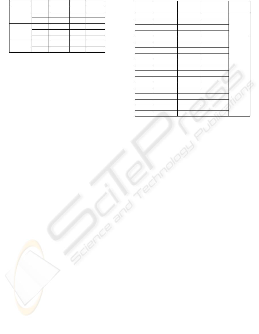
Table 3: ECs of all variables.
variable index domain valid sample
BookID EC-1 (0, +∞) yes 11
EC-2 (-∞, 0) no -2
EC-3 0 yes 0
Number EC-1 (0, +∞) yes 8
Ordered EC-2 (-∞, 0) no -9
EC-3 0 no 0
Urgent EC-1 yes yes yes
EC-2 no yes no
test suite, which was composed of a set of test cases,
with each case having as input one of the value com-
binations determined.
For example, as discussed earlier, one kind of fault
that can occur is that a particular subtask is never
posted from a plan, despite the fact that the design
indicates it should be. In the Stock Manager the plan
Out of stock response had code that, when the book
is needed urgently and the number of ordered books
is less than 100, checks if the default supplier cur-
rently has stock and if not posts the subtask Decide
supplier. We modified the body of the code for Out of
stock response so that a condition check would always
be false, thus leading to the situation that the Decide
supplier subtask event would in fact never be posted.
The plan Out of stock response had as its trigger
event No stock which included the boolean variable
Urgent. The context condition of this plan was:
(BookID ≥ 0 AND NumberOrdered > 0).
Within the body of the plan we had the code :
IF Urgent=YES AND NumberOrdered < 100
THEN postEvent(Decide supplier)
ENDIF
To introduce the fault into the system we modified
the IF condition above to be :
IF Urgent=YES AND NumberOrdered < 0
which
will of course result in Decide supplier never being
posted. The input arguments for the test are then
BookID, NumberOrdered and Urgent, with the
following specifications:
BookID, int, ≥ 0
NumberOrdered, int, > 0
Urgent, boolean
This gives the equivalence classes as shown in table
3, giving 18 possible combinations of values shown
in table 4, which is reduced to 9 if the combinatorial
testing reduction is used.
This error was discovered by the testing system by
analysing the results of the test suite and observing
that Decide supplier was never posted. The following
is an example of the warning message that is supplied
to the user:
Table 4: List of Equivalence Class combinations.
index BookID Number Urgent Validity
Ordered
1 EC-1 (11) EC-1 (8) EC-1 (yes) valid
2 EC-3 (0) EC-1 (8) EC-1 (yes)
3 EC-1 (11) EC-1 (8) EC-2 (no)
4 EC-3 (0) EC-1 (8) EC-2 (no)
5 EC-1 (11) EC-2 (-9) EC-1 (yes) invalid
6 EC-1 (11) EC-2 (-9) EC-2 (no)
7 EC-1 (11) EC-3 (0) EC-1 (yes)
8 EC-1 (11) EC-3 (0) EC-2 (no)
9 EC-2 (-2) EC-1 (8) EC-1 (yes)
10 EC-2 (-2) EC-1 (8) EC-2 (no)
11 EC-2 (-2) EC-2 (-9) EC-1 (yes)
12 EC-2 (-2) EC-2 (-9) EC-2 (no)
13 EC-2 (-2) EC-3 (0) EC-1 (yes)
14 EC-2 (-2) EC-3 (0) EC-2 (no)
15 EC-3 (0) EC-2 (-9) EC-1 (yes)
16 EC-3 (0) EC-2 (-9) EC-2 (no)
17 EC-3 (0) EC-3 (0) EC-1 (yes)
18 EC-3 (0) EC-3 (0) EC-2 (no)
Type of Fault: Subtask never posted
WARNING: The event Decide supplier is never posted in
any test case. Value combinations used in test suite were:
8
BookID=11 NumberOrdered=8 Urgent=yes
BookID=0 NumberOrdered=8 Urgent=yes
BookID=11 NumberOrdered=8 Urgent=no
BookID=0 NumberOrdered=8 Urgent=no
If some other value combination would result in posting of
event Decide supplier, please provide these values to the
testing system.
7 DISCUSSION
The need for software testing is well known and ac-
cepted. While there are many software testing frame-
works for traditional systems like Object-Oriented
software systems, there is little work on testing
Agent-Oriented systems. In particular to the best of
our knowledge there is no testing framework that is
integrated into the development methodology.
In this paper we present part of a framework for
testing agent systems that we have developed, which
performs model based unit testing. We have identi-
fied as units, plans, events that are handled by mul-
tiple plans, and plans that form cyclic dependencies.
We have presented an overview of the testing process
and mechanisms for identifying the order in which the
units are to be tested and for generating the input that
forms test cases.
8
Only valid values are provided as invalid values would
not cause the plan to run and are hence irrelevant for this
error.
ENASE 2007 - International Conference on Evaluation on Novel Approaches to Software Engineering
16

There has been some work on testing agent based
systems in recent years (e.g (Zheng and Alagar, 2005;
Seo et al., 2004)). The former provides an approach
to compare the properties of the agent and the observ-
able behaviours with the specification of the system,
by building a behavioral model for the system using
extended state machines. The latter studied how to
build a state-based model for an agent-based system
using extended Statecharts, and then proposed an ap-
proach to generate test sequences. Both of the above
work is based on conformance testing, which tests if
the system meets the business requirements and are
restricted to black-box testing. In contrast to these
approaches, our work looks at fault directed testing
which tests the internal processes of the system and
not the business requirements. Our approach is also
integrated with the design methodology and supports
testing at early stages of development.
There are other work on multi-agent testing that
defines agents as test units (e.g (Caire et al., 2004;
Rouff, 2002)). We however, explore the internals of
an agent and choose plans and events as test units.
While we obtain and use more structural informa-
tion than standard black box testing, we are limited
in the information we use as we obtain this informa-
tion from the design. Hence, implementation specific
structure is not considered. The testing framework is
also reliant on the implementation following the de-
sign specification.
Although we have completed the implementation
of the testing framework using JACK Intelligent Sys-
tems (Busetta et al., 1999), and done some prelimi-
nary evaluation as discussed in the previous section,
further evaluation is required. For this purpose we in-
tend to use programs developed by post-graduate stu-
dents as part of an agent programming course.
In this work we have only addressed unit test-
ing, in future work we will extend this work to in-
clude integration testing. To this end, we expect to
build on existing work (e.g. (Padgham et al., 2005;
Coelho et al., 2006)). The former described a debug-
ger which, similar to this work, used design artefacts
of the Prometheus methodology to provide debugging
information at run-time. Their approach of converting
protocol specifications to petri-net representations is
of particular relevance to our future work on integra-
tion testing. The latter presented a unit testing ap-
proach for multi-agent systems based on the use of
Mock-Agents, where each Mock-Agent tests a single
role of an agent under various scenarios.
As future work we also look to embed the testing
functionality into the Prometheus Design Tool (PDT)
(Thangarajah et al., 2005). PDT is a tool for develop-
ing agent systems following the Prometheus method-
ology, and includes automated code generation which
we hope to extend to generate testing specific code.
ACKNOWLEDGEMENTS
We would like to acknowledge the support of the Aus-
tralian Research Council and Agent Oriented Soft-
ware, under grant LP0453486.
REFERENCES
Apfelbaum, L. and Doyle, J. (1997). Model Based Test-
ing. In the 10th International Software Quality Week
Conference, CA, USA.
Binder, R. V. (1999). Testing Object-Oriented Systems:
Models, Patterns, and Tools. Addison-Wesley Long-
man Publishing Co., Inc., Boston, MA, USA.
Bresciani, P., Perini, A., Giorgini, P., Giunchiglia, F., and
Mylopoulos, J. (2004). Tropos: An Agent-Oriented
Software Development Methodology. Autonomous
Agents and Multi-Agent Systems, 8(3):203–236.
Busetta, P., R
¨
onnquist, R., Hodgson, A., and Lucas, A.
(1999). JACK Intelligent Agents - Components for
Intelligent Agents in Java. Technical report, Agent
Oriented Software Pty. Ltd, Melbourne, Australia.
Caire, G., Cossentino, M., Negri, A., Poggi, A., and Turci,
P. (2004). Multi-Agent Systems Implementation and
Testing. In the Fourth International Symposium: From
Agent Theory to Agent Implementation, Vienna.
Coelho, R., Kulesza, U., von Staa, A., and Lucena, C.
(2006). Unit Testing in Multi-Agent Systems using
Mock Agents and Aspects. In Proceedings of the 2006
International Workshop on Software Engineering for
Large-Scale Multi-Agent Systems, pages 83–90.
Cohen, D. M., Dalal, S. R., Fredman, M. L., and Patton,
G. C. (1997). The AETG system: An Approach to
Testing Based on Combinatiorial Design. Software
Engineering, 23(7):437–444.
Deloach, S. A. (2001). Analysis and Design using MaSE
and agentTool. In the 12th Midwest Artificial Intel-
ligence and Cognitive Science Conference (MAICS
2001), Miami University, Oxford, Ohio.
El-Far, I. K. and Whittaker, J. A. (2001). Encyclopedia of
Software Engineering, chapter Model-Based Software
Testing, pages 825–837. Wiley.
Padgham, L. and Winikoff, M. (2004). Developing Intelli-
gent Agent Systems: A practical guide. Wiley Series
in Agent Technology. John Wiley and Sons.
Padgham, L., Winikoff, M., and Poutakidis, D. (2005).
Adding Debugging Support to the Prometheus
Methodology. Engineering Applications of Artificial
Intelligence, special issue on Agent-Oriented Software
Development, 18(2):173–190.
Patton, R. (2005). Software Testing (Second Edition). Sams,
Indianapolis, IN, USA.
AUTOMATED UNIT TESTING FOR AGENT SYSTEMS
17

Rao, A. S. and Georgeff, M. P. (1995). BDI Agents:
From Theory to Practice. In Lesser, V., editor, the
First International Conference on Multi-Agent Sys-
tems, pages 312–319, San Francisco.
Rouff, C. (2002). A Test Agent for Testing Agents and
their Communities. Aerospace Conference Proceed-
ings, 2002. IEEE, 5:2638.
Seo, H.-S., Araragi, T., and Kwon, Y. R. (2004). Model-
ing and Testing Agent Systems Based on Statecharts.
volume 3236, pages 308 – 321.
Thangarajah, J., Padgham, L., and Winikoff, M. (2005).
Prometheus design tool. In the 4th International Joint
Conference on Autonomous Agents and Multi-Agent
Systems, pages 127–128, Utrecht, The Netherlands.
Zheng, M. and Alagar, V. S. (2005). Conformance Testing
of BDI Properties in Agent-based Software Systems.
In APSEC ’05: Proceedings of the 12th Asia-Pacific
Software Engineering Conference (APSEC’05), pages
457–464, Washington. IEEE Computer Society.
ENASE 2007 - International Conference on Evaluation on Novel Approaches to Software Engineering
18
